Q9DAP6061SDRAP 60 and AP 61 Single-Radio Wireless Access Point
Hewlett Packard Enterprise Company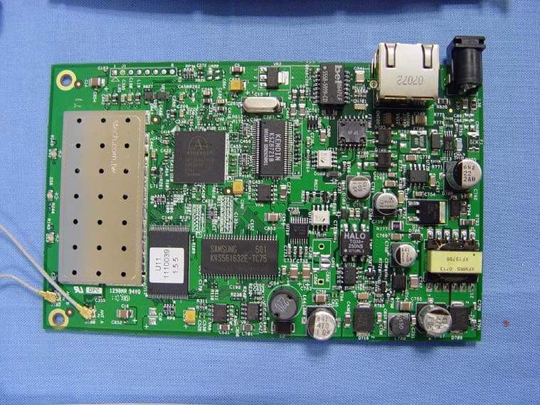
Click to zoom
Application Details
- Equipment Class
- NII - Unlicensed National Information Infrastructure TX
- Date of Grant
- Apr 21, 2008
- Application Purpose
- Original Equipment
- Date of Application
- Jul 24, 2007
- Equipment Note
- AP 60 and AP 61 Single-Radio Wireless Access Point
- Frequency Range
- 5500.00000000 - 5700.00000000
- Country
- United States
Documents & Files
Document Text
Text extracted from the exhibit documents filed with the FCC. Open a document above to read the original.
Users Manual
Technical Product Descriptions: Aruba AP 70 Dual-Radio The Aruba AP 70 is the industry's first dual-radio "hybrid" access point providing concurrent operation of 802.11a and 802.11b/g services, as well as secure wired access through an additional Ethernet port. Designed for use exclusively with Aruba Mobility Controllers , the Aruba AP 70 is ideally suited for advanced service delivery in mission-critical networks. This multi-purpose device can function both as an access point and as an RF monitor” either independently or concurrently” across the 2.4 GHz and 5 GHz spectrums. The Aruba AP 70 supports both a built-in 180 degree rotational omni directional high- gain tri-band antenna as well as support for 2.4 and 5 GHz detachable antennas. Aruba AP 65 Dual-Radio Wireless Access Point The Aruba AP 65 is Aruba’s smallest, dual-radio thin architecture access point providing concurrent operation of 802.11a and 802.11b/g services. Designed for use exclusively with Aruba mobility controllers , with its rear mounted Ethernet interface and integrated ceiling tile rail mounting point, the Aruba 65 is self- contained with a low-profile design ideally suited for discrete deployment applications. This multi-purpose device functions both as an access point and as an RF monitor— either independently or concurrently—across the 2.4 GHz and 5 GHz spectrums. And supports an integral high-gain antenna for maximum multi-band coverage. Aruba AP 60 and AP 61 Single-Radio Wireless Access Point Ideal for dense AP deployments, the Aruba AP 60 and 61 access points are dual- function, single radio 802.11a or b/g access points designed specifically for use with Aruba mobility controllers . These access points provide dedicated or shared air monitoring, giving administrators a full view of and control over the 2.4 and 5 GHz RF spectrums and eliminating the need for a discrete network of RF sensors. The Aruba AP 60 supports dual-band detachable antennas while the AP 61 provides built-in 90-degree rotational dual omni-directional high-gain antennas.
ID Label/Location Info
ARUB A NETWORKS, INC. MODEL:AP60 FCC ID:Q9DAP6061SDR IC:4675A-AP6061 TITLE: LABEL,AGENC Y DWG NO: 4000217REV 01 ARUB A WIRELESS NETWORKS INC. R 2.38 R .56 1.97 1.74 1.06 80.0 .68 .34 S C ALE 1.000 NOTES: UNLESS OTHE R WISE SPECIFIED 1. M A TERIAL: WHITE MYLAR, GLOSS Y . ADHESIVE BACKED 2. PRIN T : GRAPHICS & TEX T : 100% BLACK 3 LABE L PERIPHE R Y , NO PRINTED BORDER E234335 I. T .E. U L 2043 EN 60601-1-1 EN 60601-1-2 , AP60, RND 0681
ID Label/Location Info
MiCOM Labs, 440 Boulder Court, Suite 200, Pleasanton, CA 94566 Tel: +1 (925) 462-0304, Fax: +1 (925) 462-0306, Web: www.micomlabs.com the wireless lab July 17, 2007 ARUB11 –802.11 a/b/g Wireless Access Point AP-60 & AP-61 Aruba Networks AP60 Label Location Page 2 of 2 the wireless lab AP61 Label Location
Internal Photos
MiCOM Labs, 440 Boulder Court, Suite 200, Pleasanton, CA 94566 Tel: +1 (925) 462-0304, Fax: +1 (925) 462-0306, Web: www.micomlabs.com the wireless lab July 17, 2007 ARUB11 –802.11 a/b/g Wireless Access Point AP-60 & AP-61 Aruba Networks Internal Photographs AP 60 Motherboard front Page 2 of 4 the wireless lab AP 60 Motherboard rear Page 3 of 4 the wireless lab AP 61 Motherboard front Page 4 of 4 the wireless lab AP 61 Motherboard rear
RF Exposure Info
MiCOM Labs, 440 Boulder Court, Suite 200, Pleasanton, CA 94566 Tel: +1 (925) 462-0304, Fax: +1 (925) 462-0306, Web: www.micomlabs.com the wireless lab July 23, 2007 ARUB11-A4 Aruba Networks – 802.11 a/b/g Wireless Access Point AP-60 & AP61 Maximum Permissible Exposure Calculations FCC, Part 15 Subpart C §15.407(f) Calculations for Maximum Permissible Exposure Levels Power Density = Pd (mW/cm 2 ) = EIRP/(4πd 2 ) EIRP = P * G P = Peak output power (mW) G = Antenna numeric gain (numeric) d = Separation distance (cm) Numeric Gain = 10 ^ (G (dBi)/10) Because the EUT belongs to the General Population/Uncontrolled Exposure the limit of power density is 1.0 mW/cm 2 Antenna Gain (dBi) Numeric Gain (numeric) Peak Output Power (dBm) Peak Output Power (mW) Calculated safe distance @ max limit 1mW/ cm 2 (d=cm) 14 25.12 20.2 104.8 14.5
Test Report
COVER PAGE Test of Aruba AP-60/61 802.11a/b/g Wireless AP To: FCC 47 CFR Part 15.407 Test Report Serial No.: ARUB11-A4 Rev A TITLE PAGE TEST REPORT FROM Test of Aruba AP-60/61 802.11a/b/g Wireless AP to To: FCC 47 CFR Part 15.407 Test Report Serial No.: ARUB11-A4 Rev A Note: this report only contains data with regard to the 5,150 to 5,350 MHz, and 5,470 to 5,725 MHz operational modes of the Aruba Wireless Access Point. 2.4 and 5.8 GHz test data are reported in MiCOM Labs test report ARUB11-A2. This report supersedes None Manufacturer: Aruba Networks 1322 Crossman Avenue Sunnyvale California 94089, USA Product Function: 802.11a/b/g Wireless Access Point Copy No:pdf Issue Date: 23rd July 2007 MiCOM Labs is an ISO 17025 Accredited Testing Laboratory CERTIFICATE #2381.01 This Test Report is Issued Under the Authority of; MiCOM Labs, Inc. 440 Boulder Court, Suite 200 Pleasanton, CA 94566 USA Phone: +1 (925) 462-0304 Fax: +1 (925) 462-0306 www.micomlabs.com This test report may be reproduced in full only. The document may only be updated by MiCOM Labs personnel. Any changes will be noted in the Document History section of the report. Title: To: Serial #: Issue Date: Page: 47 CFR Part 15.407 Aruba AP-60/61 802.11a/b/g Wireless AP FCC ARUB11-A4 Rev A 23rd July 2007 3 of 126 This page has been left intentionally blank Title: To: Serial #: Issue Date: Page: 47 CFR Part 15.407 This test report may be reproduced in full only. The document may only be updated by MiCOM Labs personnel. Any changes will be noted in the Document History section of the report. MiCOM Labs, 440 Boulder Court, Suite 200, Pleasanton, CA 94566 USA, Phone: 925.462.0304, Fax: 925.462.0306, www.micomlabs.com Aruba AP-60/61 802.11a/b/g Wireless AP FCC ARUB11-A4 Rev A 23rd July 2007 4 of 126 TABLE OF CONTENTS ACCREDITATION & LISTINGS......................................................................................... 6 1. TEST RESULT CERTIFICATE................................................................................... 9 2. REFERENCES AND MEASUREMENT UNCERTAINTY........................................ 10 2.1. Normative References............................................................................................. 10 2.2. Test and Uncertainty Procedures............................................................................ 11 3. PRODUCT DETAILS AND TEST CONFIGURATIONS.......................................... 12 3.1. Technical Details..................................................................................................... 12 3.2. Scope of Test Program............................................................................................ 13 3.3. Equipment Model(s) and Serial Number(s)............................................................. 16 3.4. Antenna Details....................................................................................................... 16 3.5. Cabling and I/O Ports.............................................................................................. 17 3.6. Test Configurations.................................................................................................. 17 3.7. Equipment Modifications.......................................................................................... 18 3.8. Deviations from the Test Standard.......................................................................... 18 4. TEST SUMMARY...................................................................................................... 19 5. TEST RESULTS........................................................................................................ 22 5.1. Device Characteristics............................................................................................. 22 5.1.1. 26 dB and 99 % Bandwidth........................................................................ 22 5.1.2. Transmit Output Power............................................................................... 30 5.1.3. Peak Power Spectral Density..................................................................... 34 5.1.4. Peak Excursion Ratio................................................................................. 42 5.1.5. Frequency Stability..................................................................................... 50 5.1.6. Maximum Permissible Exposure................................................................ 51 5.1.7. Radiated Emissions.................................................................................... 52 5.1.8. AC Wireline Conducted Emissions (150 kHz – 30 MHz)............................ 83 6. Dynamic Frequency Selection (DFS)..................................................................... 86 6.1. Test Procedure and Setup....................................................................................... 86 6.1.1. Interference Threshold values, Master or Client incorporating In-Service Monitoring ................................................................................................... 86 6.1.2. DFS Response requirement values............................................................ 86 6.1.3. Radar Test Waveforms............................................................................... 87 6.1.4. Frequency Hopping Radar Test Waveform................................................ 90 6.1.5. Radar Waveform Calibration...................................................................... 90 6.1.6. Radar Waveform Calibration Plots............................................................. 91 6.1.7. Test Set Up:................................................................................................ 97 Title: To: Serial #: Issue Date: Page: 47 CFR Part 15.407 This test report may be reproduced in full only. The document may only be updated by MiCOM Labs personnel. Any changes will be noted in the Document History section of the report. MiCOM Labs, 440 Boulder Court, Suite 200, Pleasanton, CA 94566 USA, …
Text truncated - open the document above for the full version.
Test Setup Photos
MiCOM Labs, 440 Boulder Court, Suite 200, Pleasanton, CA 94566 Tel: +1 (925) 462-0304, Fax: +1 (925) 462-0306, Web: www.micomlabs.com the wireless lab July 17, 2007 ARUB11 –802.11 a/b/g Wireless Access Point AP-60 & AP-61 Aruba Networks TEST SET-UP PHOTOGRAPHS General Measurement Test Set-Up Page 2 of 6 the wireless lab Radiated Emissions (30 MHz-1 GHz) Page 3 of 6 the wireless lab Spurious Emissions >1 GHz Page 4 of 6 the wireless lab AC Wireline Emissions (150 kHz - 30 MHz) Page 5 of 6 the wireless lab General DFS Test Setup Page 6 of 6 the wireless lab DFS Test Equipment
Contact Information
Applicant
Mark Hill(Principal Engineer)
Test Firm
Micom LabsGordon Hurst
Technical Specifications
| # | Rule Parts | Frequency Range | Power Output |
|---|---|---|---|
| 3 | 15E | 5.50 GHz - 5.70 GHz | 104.70 mW |
Other Applications from Hewlett Packard Enterprise Company
Q9DAPINH721
Jul 17, 2026Access Point
Equipment Class
6ID - 15E 6 GHz Low Power Indoor Access PointQ9DASIN0307
Dec 22, 2025HPE Aruba User Experience Sensor
Equipment Class
DTS - Digital Transmission SystemQ9DASIN0308
Nov 23, 2025HPE Aruba User Experience Sensor
Equipment Class
DTS - Digital Transmission SystemQ9DAPEX0764
Nov 20, 2025ACCESS POINT
Equipment Class
DTS - Digital Transmission SystemQ9DAPIN0763
Sep 29, 2025ACCESS POINT
Equipment Class
NII - Unlicensed National Information Infrastructure TX