Q9DAP85AP-85 Dual-Radio Wireless Access Point
Hewlett Packard Enterprise Company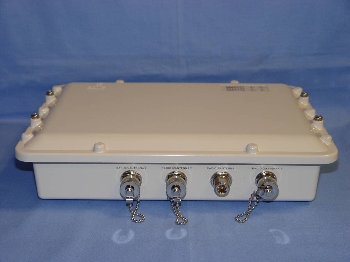
Click to zoom
Application Details
- Equipment Class
- DTS - Digital Transmission System
- Date of Grant
- Sep 26, 2007
- Application Purpose
- Original Equipment
- Date of Application
- Sep 26, 2007
- Equipment Note
- AP-85 Dual-Radio Wireless Access Point
- Frequency Range
- 5745.00000000 - 5825.00000000
- Country
- United States
Documents & Files
Document Text
Text extracted from the exhibit documents filed with the FCC. Open a document above to read the original.
Users Manual
Aruba AP-85 Outdoor Access Point Series Installation Guide www.arubanetworks.com 1322 Crossman Avenue Sunnyvale, California 94089 Phone: 408.227.4500 Fax 408.227.4550 Aruba AP-85 Outdoor Access Point Series | Installation Guide0510323-03 | September 2007 Copyright © 2007 Aruba Networks All rights reserved. Trademarks Aruba Networks ® is a registered trademark, and Mobility Management System, RFprotect, and Bluescanner are trademarks of Aruba Networks, Inc. All other trademarks or registered trademarks are the property of their respective holders. Specifications are subject to change without notice. Legal Notice The use of Aruba Networks, Inc. switching platforms and software, by all individuals or corporations, to terminate other vendors' VPN client devices constitutes complete acceptance of liability by that individual or corporation for this action and indemnifies, in full, Aruba Networks, Inc. from any and all legal actions that might be taken against it with respect to infringement of copyright on behalf of those vendors. Warranty This hardware product is protected by the standard Aruba warranty of one year parts/labor. For more information, refer to the ARUBACARE SERVICE AND SUPPORT TERMS AND CONDITIONS. Altering this device (such as painting it) voids the warranty. Aruba AP-85 Outdoor Access Point Series| Installation GuideContents |3 Contents PrefaceGuide Overview5 Related Documents5 Contacting Aruba6 Chapter 1AP-85 Series Hardware Overview7 About the AP-85 Series7 AP-85 Series Operation7 Minimum Software Requirements8 Package Checklist8 Hardware Model Overview9 AP-85 Series Front View9 AP-85 Series Rear View9 AP-85 Series Top View10 AP-85TX Bottom View10 AP-85FX/LX Bottom View11 LED Status Indicators12 Optional Accessories13 Chapter 2Outdoor Planning and Deployment Considerations15 Planning and Deployment Considerations15 Scale Requirements15 Identifying Known RF Absorbers/Reflectors/Interferences Sources15 RF Absorbers15 RF Reflectors15 RF Interference Sources15 Line of Sight (Radio Path Planning)16 Antenna Height17 Antenna Position and Orientation18 Radio Interference18 Weather Conditions19 Ethernet Cabling19 Grounding19 Chapter 3AP-85 Series Installation21 Pre-Installation Network Setup21 Pre-Installation Checklist21 Access Point Setup21 1. Verifying Pre-Installation Connectivity22 2. Provisioning the AP22 3. Installing the AP-8522 Mounting the AP-8523 Positioning the AP-8527 Connecting Required Cables28 Lightning Arrestor Installation30 Antenna Installation30 4. Verifying Post-Installation Connectivity30 5. Configuring the AP-8530 AP Configuration30 4|ContentsAruba AP-85 Outdoor Access Point Series| Installation Guide Appendix AUnderstanding Antennas31 Aruba Antennas31 Understanding Wireless Antennas31 Omni-Directional vs. Directional Coverage31 Antenna Beamwidth, Pattern, and Gain Considerations32 Understanding Antenna Pattern Plots and Specifications34 Detachable Antenna Selection35 Detachable Outdoor Antenna Types35 Detachable Antenna Selection Tips35 Appendix BProduct Specifications41 Mechanical (AP-85TX, AP-85FX, and AP-85LX)41 Electrical42 AP-85TX42 AP-85FX42 AP-85LX42 Maximum Power Draw42 Wireless LAN43 Safety and Regulatory Compliance43 Proper Disposal of Aruba Equipment43 Waste of Electrical and Electronic Equipment44 European Union RoHS44 China RoHS44 Index45 Aruba AP-85 Outdoor Access Point Series| Installation GuidePreface |5 Preface This preface includes the following information: zAn overview of the contents of this manual zA list of related documentation for further reading zAruba Networks support and service information Guide Overview zChapter 1, “AP-85 Series Hardware Overview” on page 7 provides a detailed hardware overview of the three AP-85 models: the AP-85TX, the AP-85FX, and the AP-85LX. zChapter 2, “Outdoor Planning and Deployment Considerations” on page 15 provides key questions to ask and items to consider when deploying an outdoor wireless network. zChapter 3, “AP-85 Series Installation” on page 21 describes the multi-step process for successful installation and deployment of an AP-85. zAppendix A, “Understanding Antennas” on page 31 provides key tools that will help you understand Aruba antenna specifications. zAppendix B, “Product Specifications” on page 41 includes product technical specifications and safety and regulatory compliance information. Related Documents The following documents are referred to in this guide and are considered components of the complete documentation set needed for successful AP deployment and management: zArubaOS Quick Start Guide zArubaOS User Guide zAruba Mobility Management System User Guide zAruba Outdoor Antenna Specifications 6| PrefaceAruba AP-85 Outdoor Access Point Series| Installation Guide Contacting Aruba Web Site Support Main Sitehttp://www.arubanetworks.com Support Sitehttp://www.arubanetworks.com/support Software Licensing Sitehttps://licensing.arubanetworks.com Wireless Security Incident Response Team (WSIRT) http://www.arubanetworks.com/support/wsirt.php Support [email protected] WSIRT Email Please email details of any security problem found in an Aruba product. [email protected] Telephone Support Aruba Headquarters+1 (408) 227-4500 FAX+1 (408) 227-4550 Customer Support zUnited States zFrance zUnited Kingdom zGermany zAll Other Countries 800-WI-FI-LAN (800-943-4526) +33 (0) 1 70 72 55 59 +44 (0) 20 7127 5989 +49 (0) 69 38 09 77 22 8 +1 (408) 754-1200 Aruba AP-85 Outdoor Access Point Series| Installation GuideAP-85 Series Hardware Overview |7 Chapter 1 AP-85 Series Hardware Overview About the AP-85 Series The AP-85 Series consists of resilient, environmentally hardened, outdoor rated, dual-band IEEE 802.11a/b/g devices, which can be configured for deployment as a wireless access point, air monitor, mesh point, or mesh portal. This outdoor access point series is part of Aruba’s comprehensive wireless network solution. The AP-85 Series works only in conjunction with an Aruba Mobility Con…
Text truncated - open the document above for the full version.
Users Manual
24| AP-85 Series InstallationAruba AP-85 Outdoor Access Point Series| Installation Guide 2. Seat the AP-85 into the four keyholes on the mounting plate and tighten down the four mounting bolts (M8 bolts) to secure the AP-85 in place (see Figure 12). The mounting plate should rest between the captive flat washer on each of the mounting bolts and the rear of the AP-85. Figure 12 Wall Mounting the AP-85 Pole Mounting the AP-85 (1.5” to 3.5” Diameter) To mount an AP-85 to a pole with a diameter of 1.5” to 3.5”: 1. Slide the long T-bolt through the opening in the mounting bracket (see Figure 13). 2. Attach the included retaining clip to the T-bolt (see Figure 13). 3. Screw the included nut onto the end of the T-bolt (see Figure 13). 4. Secure the mounting plate to the mounting bracket using the four included phillips head screws (see Figure 13). Figure 13 Assembling the Pole Mounting Bracket NOTE The positioning of the keyholes on the mounting plate supports horizontal or vertical mounting of the AP-85, which is achieved by rotating the device by 90 degrees and securing it to the mounting plate. Mounting Bolts Mounting Plate AP-85 Wall arun 0137 Nut (1x) T-Bolt (1x) Phillips Head Screws (4x) Mounting Bracket Mounting Plate Retaining Clip Aruba AP-85 Outdoor Access Point Series| Installation GuideAP-85 Series Installation |25 5. Wrap the pole mounting bracket around a 1.5” to 3.5” diameter pole and secure the bracket in place (see Figure 14). a. Wrap the pole mounting bracket around the pole. b. Slip the end of the T-bolt with nut through the opening in the pole mounting bracket. c. Maneuver the T-bolt to the top slot in the pole mounting bracket and tighten down the nut. Ensure that the nut is tightly secured and that the bracket cannot move. It must be secure to support the weight of the AP-85. Figure 14 Securing the Pole Mounting Bracket 6. Seat the AP-85 into the four keyholes on the mounting plate and tighten down the four mounting bolts (M8 bolts) to secure the AP-85 in place (see Figure 15). The mounting plate should rest between the captive flat washer on each of the mounting bolts and the rear of the AP-85. Figure 15 Vertical Pole Mount Position (1.5” to 3.5” Diameter) arun_0130 arun_0129 Step A Step B Step C NOTE The pole mounting bracket can be secured to a horizontal or vertical pole. The positioning of the keyholes on the bracket supports horizontal or vertical mounting of the AP-85 on either pole type, which is achieved by rotating the device by 90 degrees and securing it to the bracket. Refer to Figure 15 and Figure 16 for details. Secured Mounting Bracket Tightened Mounting Bolts AP-85 Pole 26| AP-85 Series InstallationAruba AP-85 Outdoor Access Point Series| Installation Guide Figure 16 Horizontal Pole Mount Position (1.5” to 3.5” Diameter) Pole Mounting the AP-85 (>3.5” Diameter) To mount an AP-85 to a pole with a diameter greater than 3.5”: 1. Attach the mounting plate to the pole using outdoor rated straps (see Figure 17). Outdoor rated straps are not included with the unit and must be purchased separately. 2. Seat the AP-85 into the four keyholes on the mounting plate and tighten down the four mounting bolts (M8 bolts) to secure the AP-85 in place (see Figure 17). The mounting plate should rest between the captive flat washer on each of the mounting bolts and the rear of the AP-85. Figure 17 Pole Mounting the AP-85 (>3.5” Diameter) arun_0131C Secured Mounting Bracket Tightened Mounting Bolts AP-85 Horizontal Pole NOTE The mounting plate can be secured to a horizontal or vertical pole. The positioning of the keyholes on the mounting plate supports horizontal or vertical mounting of the AP-85 on either pole type, which is achieved by rotating the device by 90 degrees and securing it to the mounting plate. Outdoor Rated Straps Mounting Plate Mounting Bolts AP-85 Pole Aruba AP-85 Outdoor Access Point Series| Installation GuideAP-85 Series Installation |27 Positioning the AP-85 To adjust the angle of an AP-85 on a vertical pole: 1. Loosen the four M8 bolts on the side of the mounting plate and rotate the AP to the desired angle and tighten down the M8 bolts (see Figure 18). Figure 18 Positioning the AP-85 on a Vertical Pole To adjust the angle of an AP-85 on a horizontal pole: 1. Rotate the entire mounting bracket to the desired angle and tighten the bracket into place (see Figure 19). Figure 19 Positioning the AP-85 on a Horizontal Pole M8 Positioning Bolts (4x, 2x per side) arun_0131D arun_0131E 28| AP-85 Series InstallationAruba AP-85 Outdoor Access Point Series| Installation Guide Connecting Required Cables RJ-45 CAT 5 Cable To weatherproof and connect an RJ-45 terminated CAT 5E or better cable to an AP-85 (see Figure 20), perform the following using the contents in the included kit that ships with your unit: 1. Slide the cap over the terminated cable. 2. Slide the rubber grommet over the terminated cable. 3. Slide the connector shell over the terminated cable. 4. Slide the washer over the terminated cable. 5. Insert the rubber grommet into the top of the connector shell until the top surface of the grommet is flush with the top edge of the connector shell. 6. Connect the terminated cable to the proper port: LAN/POE port on the AP-85TX model or the CONSOLE port on the AP-85FX/LX models. 7. Screw the connector shell onto the interface on the AP-85. 8. Screw the cap onto the connector shell. Figure 20 Weatherproofing and Connecting an RJ-45 Terminated CAT 5 Cable NOTE The cable is not included and must be purchased separately. Purchase a suitable UV resistant, outdoor rated, CAT 5E or better RJ-45 cable for use with the AP-85. arun_0127 Cap Rubber Grommet Connector Shell Washer Terminated CAT 5E or Better Cable Aruba AP-85 Outdoor Access Point Series| Installation GuideAP-85 Series Installation |29 DC and AC Power Cables To connect the power cables (wiring harnesses): 1. Screw the two-wire, 8-foot long DC power cable (wiring harness) to the DC interface on the AP- 85TX, AP-85…
Text truncated - open the document above for the full version.
Users Manual
Aruba AP-85 Outdoor Access Point Series| Installation GuideUnderstanding Antennas |35 It is evident from Figure 27 that 2-D pattern plots typically provided in antenna specifications are a simplification of the real 3-D situation. Often, 2-D plots are reduced even further to a set of simple specifications based on the antenna gain and 3 dB beamwidth. Detachable Antenna Selection Select the correct antenna type to support the required frequency band (2.4 GHz or 5 GHz) and desired coverage pattern. To select the correct antenna type for the deployment, download and read Aruba’s outdoor antenna specifications: http://www.arubanetworks.com/products/access-points/antennas.php. Detachable Outdoor Antenna Types These are some of the terms used to describe Aruba’s detachable antenna offerings. Terminology and degree of sector in Aruba’s antenna specifications are determined by the horizontal 3 dB beamwidth. zDown-Tilt: An omni-directional antenna that focuses its energy downwards. zSector/Patch: A directional antenna that provides a focused sector of coverage from a central point (Example: +/- 45 degrees from a 90 degree center point). zPanel: A flat formed antenna that directs energy to a sector of coverage. This type of antenna is often ideal for point-to-point WDS bridging or wireless mesh backhaul applications. Detachable Antenna Selection Tips zIf omni-directional coverage is desired with the greatest possible horizontal range from the AP, select one of Aruba's detachable antennas with high-gain, omni-directional coverage. Due to the tight vertical beamwidth of high-gain, omni-directional antennas, this typically requires mounting the antenna not more than 5 meters (16.5 feet) above the expected client locations in elevation. zIf omni-directional coverage is desired, but only high mounting locations are available (approx. 5 m (16.5 feet) to 10 m (33 feet), consider the use of lower gain (3 dBi to 5 dBi) omni- directional antennas and a denser AP deployment. The lower gain antenna will reduce the maximum horizontal range of the AP, but will provide better vertical coverage. zFor very high mounting locations (>10 m/33 feet) such as light poles or monopoles, consider the use of an omni-directional antenna with electrical downtilt. A downtilt omni-directional antenna is an antennas that has a direction of maximum gain at approximately 45° down from horizontal. NOTE All figures are shown with a 100 meter (328 feet) mounting height above the ground and for a 18 Mbps coverage area. 36| Understanding AntennasAruba AP-85 Outdoor Access Point Series| Installation Guide Figure 29 AP-ANT-90 E-Plane View (Side View) Figure 30 AP-ANT-90 H-Plane View (Top View) zAlternatively, for high mounting locations, high-gain sector antennas may be used with mechanical downtilt. This will typically require the use of multiple access points per mounting location to provide omni-directional coverage. zIf a directional antenna is required to direct RF coverage, the detachable antenna must be capable of supporting all of the frequency bands that require support (2.4 GHz and/or 5 GHz). zDirectional antennas are selected to focus RF energy more efficiently to a targeted area. zDirectional antennas are also useful in areas where the surrounding materials have high amounts of RF attenuation or reflection and the RF signal needs to be guided in the direction of the least Aruba AP-85 Outdoor Access Point Series| Installation GuideUnderstanding Antennas |37 amount of attenuation or reflection. For example, when mounting antennas on the outside surfaces of a building to provide coverage to outdoor spaces in front of the building, a directional antenna can be used to direct the coverage away from the building. High Mounting Omni-Directional Antenna Scenario (AP-ANT-80 vs. AP-ANT-90) The AP-ANT-80 shows greater horizontal range due to its higher gain (8 dBi vs. 3 dBi) antenna, but in this very high mounting situation, the AP-ANT-90 may be a better choice for ground level coverage because the direction of maximum gain is directed downward toward the ground. This situation could potentially be improved if a lower mounting elevation was available for the AP-ANT-80, ideally about 5 m above Ground. Figure 31 AP-ANT-80 E-Plane View (Side View) Figure 32 AP-ANT-80 H-Plane View (Top View) 38| Understanding AntennasAruba AP-85 Outdoor Access Point Series| Installation Guide High Mounting Directional Antenna Scenario The AP-ANT-82 is a high gain (12 dBi), directional antenna with a 90 degree 3 dB beamwidth in azimuth. For this high mounting condition, this antenna provides a long range in the direction of maximum gain, but it would require mechanical downtilt for ground level coverage. Figure 33 AP-ANT-82 E-Plane View (Side View) Figure 34 AP-ANT-82 with 30 Degree Downtilt E-Plane View (Side View) Aruba AP-85 Outdoor Access Point Series| Installation GuideUnderstanding Antennas |39 Figure 35 AP-ANT-82 H-Plane View (Top View) Figure 36 AP-ANT-82 with 30 Degree Downtilt H-Plane View (Top View) 40| Understanding AntennasAruba AP-85 Outdoor Access Point Series| Installation Guide Aruba AP-85 Outdoor Access Point Series| Installation GuideProduct Specifications |41 Appendix B Product Specifications Product Specifications Mechanical (AP-85TX, AP-85FX, and AP-85LX) zDevice Dimensions (HxWxD): 10.80” x 12.64” x 3.07” 274 mm x 321 mm x 78 mm zDevice Weight: 7.40 lbs/3.36 kgs zDevice Weight with Mounting Plate: 9.65 lbs/4.38 kgs zDevice Weight with Mounting Plate and Mounting Bracket: 10.85 lbs/4.92 kgs zShipping Dimensions: 15.7” x 12.2” x 9.3” 399 mm x 310 mm x 236 mm zShipping Weight: 13.50 lbs/6.12 kgs zTemperature: Operating: -30ºC to 55ºC (-22ºF to 131ºF) Storage: -40ºC to 70ºC (-40ºF to 158ºF) zRelative Humidity: 0% to 95% non-condensing zAltitude: 0-3000 m (0-9850 ft) zSurvival Wind Speed: 125 mph (201 km/hr) zMounting: Articulating adjustable pole or mast mount kit (included) Antenna mount bracket (optional) zAntenna: Quad, N-type F…
Text truncated - open the document above for the full version.
External Photos
MiCOM Labs, 440 Boulder Court, Suite 200, Pleasanton, CA 94566 Tel: +1 (925) 462-0304, Fax: +1 (925) 462-0306, Web: www.micomlabs.com the wireless lab September 19, 2007 ARUB14 –802.11 a/b/g Wireless Access Point AP-85TX Aruba Networks External Photographs EUT Front View Page 2 of 3 the wireless lab EUT Side View Page 3 of 3 the wireless lab EUT Side View
ID Label/Location Info
4675A-AP85
ID Label/Location Info
MiCOM Labs, 440 Boulder Court, Suite 200, Pleasanton, CA 94566 Tel: +1 (925) 462-0304, Fax: +1 (925) 462-0306, Web: www.micomlabs.com the wireless lab September 19, 2007 ARUB14 –802.11 a/b/g Wireless Access Point AP-85TX Aruba Networks Label Location
Internal Photos
MiCOM Labs, 440 Boulder Court, Suite 200, Pleasanton, CA 94566 Tel: +1 (925) 462-0304, Fax: +1 (925) 462-0306, Web: www.micomlabs.com the wireless lab September 19, 2007 ARUB14 –802.11 a/b/g Wireless Access Point AP-85TX Aruba Networks Internal Photographs Motherboard assembly bottom Page 2 of 5 the wireless lab Motherboard top with RF assemblies Page 3 of 5 the wireless lab Motherboard top with RF assemblies removed Page 4 of 5 the wireless lab RF assemblies top Page 5 of 5 the wireless lab RF assemblies bottom
RF Exposure Info
440 Boulder Court, Suite 200, Pleasanton, California 94566, USA Tel.: +1 925 462 0304, Fax: +1 925 462 0306 www.micomlabs.com 20 th September 2007 ARUB14–A2 Aruba Networks – AP-85TX 802.11 a/b/g Wireless AP Maximum Permissible Exposure FCC, Part 15 Subpart C §15.247(i) Industry Canada RSS-Gen §5.5 Calculations for Maximum Permissible Exposure Levels Power Density = Pd (mW/cm 2 ) = EIRP/(4πd 2 ) EIRP = P * G P = Peak output power (mW) G = Antenna numeric gain (numeric) d = Separation distance (cm) Numeric Gain = 10 ^ (G (dBi)/10) Because the EUT belongs to the General Population/Uncontrolled Exposure the limit of power density is 1.0 mW/cm 2 Freq. Band (GHz) Antenna Gain (dBi) Numeric Gain (numeric) Peak Output Power (dBm) Peak Output Power (mW) Calculated Safe Distance @ 1mW/cm 2 Limit(cm) Minimum Separation Distance (cm) 2.4(b) 18 63.10 +18.0 63.1 17.8 20* 2.4(g) 18 63.10 +18.0 63.1 17.8 20* 5.8 16 39.81 +20.0 100.0 17.8 20* *Note: for mobile or fixed location transmitters the minimum separation distance is 20cm, even if calculations indicate the MPE distance to be less. Specification Maximum Permissible Exposure Limits §15.247(i) Systems operating under the provisions of this section shall be operated in a manner that ensures that the public is not exposed to radio frequency levels in excess of the Commission’s guidelines. FCC §1.1310 Limit = 1mW / cm 2 from 1.310 Table 1 RSS-Gen §5.5 Before equipment certification is granted, the applicable requirements of RSS-102 shall be met.
Test Report
COVER PAGE Test of Aruba AP-85TX 802.11 a/b/g Wireless AP To: FCC 47 CFR Part 15.247 & IC RSS-210 Test Report Serial No.: ARUB14-A2 Rev A TITLE PAGE TEST REPORT FROM Test of Aruba AP-85TX 802.11 a/b/g Wireless AP to To FCC 47 CFR Part 15.247 & IC RSS-210 Test Report Serial No.: ARUB14-A2 Rev A This report supersedes: None Manufacturer: Aruba Networks 1322 Crossman Avenue Sunnyvale CA 94089, USA Product Function: 802.11 a/b/g Wireless Access Point Copy No: pdf Issue Date: 26th September 2007 This Test Report is Issued Under the Authority of; MiCOM Labs, Inc. 440 Boulder Court, Suite 200 Pleasanton, CA 94566 USA Phone: +1 (925) 462-0304 Fax: +1 (925) 462-0306 Hwww.micomlabs.com H CERTIFICATE #2381.01 MiCOM Labs is an ISO 17025 Accredited Testing Laboratory This test report may be reproduced in full only. The document may only be updated by MiCOM Labs personnel. Any changes will be noted in the Document History section of the report. Title: Aruba AP-85TX 802.11 a/b/g Wireless AP To: Serial #: Issue Date: Page: FCC 47 CFR Part 15.247 & IC RSS-210 ARUB14-A2 Rev A 26th September 2007 3 of 106 This test report may be reproduced in full only. The document may only be updated by MiCOM Labs personnel. Any changes will be noted in the Document History section of the report. This page has been left intentionally blank MiCOM Labs, 440 Boulder Court, Suite 200, Pleasanton, CA 94566 USA, Phone: 925.462.0304, Fax: 925.462.0306, www.micomlabs.com Title: Aruba AP-85TX 802.11 a/b/g Wireless AP To: Serial #: Issue Date: Page: FCC 47 CFR Part 15.247 & IC RSS-210 ARUB14-A2 Rev A 26th September 2007 4 of 106 This test report may be reproduced in full only. The document may only be updated by MiCOM TABLE OF CONTENTS COVER PAGE....................................................................................................................1 TITLE PAGE....................................................................................................................... 2 ACCREDITATION, LISTINGS and RECOGNITION.........................................................5 1. TEST RESULT CERTIFICATE...................................................................................8 2. REFERENCES AND MEASUREMENT UNCERTAINTY..........................................9 2.1. Normative References...............................................................................................9 2.2. Test and Uncertainty Procedures..............................................................................9 3. PRODUCT DETAILS AND TEST CONFIGURATIONS..........................................10 3.1. Technical Details.....................................................................................................10 3.2. Scope of Test Program............................................................................................11 3.3. Equipment Model(s) and Serial Number(s).............................................................12 3.4. Antenna Details.......................................................................................................12 3.5. Cabling and I/O Ports..............................................................................................12 3.6. Test Configurations..................................................................................................13 3.7. Equipment Modifications..........................................................................................14 3.8. Deviations from the Test Standard..........................................................................15 3.9. Subcontracted Testing or Third Party Data.............................................................15 4. TEST SUMMARY......................................................................................................16 5. TEST RESULTS........................................................................................................18 5.1. Device Characteristics.............................................................................................18 5.1.1. 6 dB and 99 % Bandwidth........................................................................18 5.1.2. Peak Output Power..................................................................................32 5.1.3. Peak Power Spectral Density...................................................................46 5.1.4. Maximum Permissible Exposure..............................................................57 5.1.5. Conducted Spurious Emissions...............................................................58 5.1.6. Radiated Emissions.................................................................................75 5.1.7. AC Wireline Conducted Emissions (150 kHz – 30 MHz)........................100 6. PHOTOGRAPHS.....................................................................................................103 6.1. Radiated Spurious Emissions................................................................................103 6.2. General Measurement Test Set-Up.......................................................................104 Labs personnel. Any changes will be noted in the Document History section of the report. MiCOM Labs, 440 Boulder Court, Suite 200, Pleasanton, CA 94566 USA, Phone: 925.462.0304, Fax: 925.462.0306, www.micomlabs.com 7. TEST EQUIPMENT DETAILS.................................................................................105 Title: Aruba AP-85TX 802.11 a/b/g Wireless AP To: Serial #: Issue Date: Page: FCC 47 CFR Part 15.247 & IC RSS-210 ARUB14-A2 Rev A 26th September 2007 5 of 106 This test report may be reproduced in full only. The document may only be updated by MiCOM ACCREDITATION, LISTINGS and RECOGNITION ACCREDITITION MiCOM Labs, Inc. an accredited laboratory complies with the international standard BS EN ISO/IEC 17025. The company is accredited by the American Association for Laboratory Accreditation (A2LA) www.a2la.org test laboratory number 2381.01. MiCOM Labs test schedule is avai…
Text truncated - open the document above for the full version.
Test Setup Photos
MiCOM Labs, 440 Boulder Court, Suite 200, Pleasanton, CA 94566 Tel: +1 (925) 462-0304, Fax: +1 (925) 462-0306, Web: www.micomlabs.com the wireless lab September 19, 2007 ARUB14 –802.11 a/b/g Wireless Access Point AP-85TX Aruba Networks TEST SET-UP PHOTOGRAPHS General Measurement Test Set-Up Page 2 of 2 the wireless lab Radiated Spurious Emissions
Contact Information
Applicant
Mark Hill(Principal Engineer)
Technical Contact
Aurba Networks, Inc.Michael T Smith
[email protected]408-754-1212
1322 Crossman Ave. · Sunnyvale, California · United States
Test Firm
Micom LabsGordon Hurst
Technical Specifications
| # | Rule Parts | Frequency Range | Power Output |
|---|---|---|---|
| 2 | 15C | 5.75 GHz - 5.83 GHz | 234.00 mW |
Other Applications from Hewlett Packard Enterprise Company
Q9DAPINH721
Jul 17, 2026Access Point
Equipment Class
6ID - 15E 6 GHz Low Power Indoor Access PointQ9DASIN0307
Dec 22, 2025HPE Aruba User Experience Sensor
Equipment Class
DTS - Digital Transmission SystemQ9DASIN0308
Nov 23, 2025HPE Aruba User Experience Sensor
Equipment Class
DTS - Digital Transmission SystemQ9DAPEX0764
Nov 20, 2025ACCESS POINT
Equipment Class
DTS - Digital Transmission SystemQ9DAPIN0763
Sep 29, 2025ACCESS POINT
Equipment Class
NII - Unlicensed National Information Infrastructure TX