Q9DAPIN0103Wireless Access Point
Hewlett Packard Enterprise Company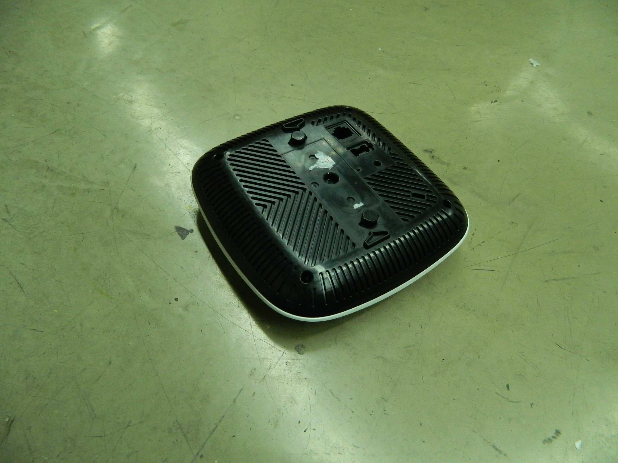
Click to zoom
Application Details
- Equipment Class
- NII - Unlicensed National Information Infrastructure TX
- Date of Grant
- Mar 04, 2014
- Application Purpose
- Original Equipment
- Date of Application
- Feb 19, 2014
- Equipment Note
- Wireless Access Point
- Frequency Range
- 5180.00000000 - 5240.00000000
- Country
- United States
Documents & Files
Document Text
Text extracted from the exhibit documents filed with the FCC. Open a document above to read the original.
Users Manual
AP-103 Wireless Access Point Installation Guide The Aruba AP-103 wireless access point supports the IEEE 802.11n standard for high-performance WLAN. This access point uses MIMO (Multiple-in, Multiple- out) technology and other high-throughput mode techniques to deliver high- performance, 802.11n 2.4 GHz or 5 GHz functionality while simultaneously supporting existing 802.11a/b/g wireless services. The AP-103 access point works only in conjunction with an Aruba Controller. The Aruba AP-103 access point provides the following capabilities: Wireless transceiver Protocol-independent networking functionality IEEE 802.11a/b/g/n operation as a wireless access point IEEE 802.11a/b/g/n operation as a wireless air monitor Compatibility with IEEE 802.3af PoE Central management configuration and upgrades through a controller Package Contents AP-103 access point 9/16" and 15/16” Ceiling Rail Adapters Installation guide (this document) AP-103 Hardware Overview Figure 1 AP-103 LEDs LEDs The AP-103 is equipped with four LEDs that indicate the status of the various components of the AP. PWR: Indicates whether or not the AP-103 is powered-on ENET: Indicates the status of the AP-103’ Ethernet port 5 GHz: Indicates the status of the 802.11a/n radio 2.4 GHz: Indicates the status of the 802.11b/g/n radio Figure 2 AP-103 Rear Console Port The serial console port allows you to connect the AP to a serial terminal or a laptop for direct local management. This port is a 4-pin connector covered by a dust cover. Ethernet Port AP-103 is equipped with one 10/100/1000Base-T (RJ-45) auto-sensing, MDI/MDX wired-network connectivity port. This port supports IEEE 802.3af Power over Ethernet (PoE) compliance, accepting 48 VDC (nominal) as a standard defined Powered Device (PD) from a Power Sourcing Equipment (PSE) such as a PoE midspan injector, or network infrastructure that supports PoE. The 10/100/1000 Mbps Ethernet port is on the back of the AP. The port has RJ-45 female connectors with the pin-outs shown in Figure 3. Figure 3 Gigabit Ethernet Port Pin-Out DC Power Socket If PoE is not available, an optional Aruba AP AC-DC adapter kit (sold separately) can be used to power the AP-103. Additionally, a locally-sourced AC-to-DC adapter (or any DC source) can be used to power this device, as long as it complies with all applicable local regulatory requirements and the DC interface meets the following specifications: 12 VDC (+/- 5%)/18W Center-positive 1.7/4.0 mm circular plug, 9.5 mm length Reset Button The reset button can be used to return the AP to factory default settings. To reset the AP: 1. Power off the AP. 2. Press and hold the reset button using a small, narrow object, such as a paperclip. 3. Power-on the AP without releasing the reset button. The power LED will flash within 5 seconds. 4. Release the reset button. The power LED will flash again within 15 seconds indicating that the reset is completed. The AP will now continue to boot with the factory default settings. Before You Begin Pre-Installation Network Requirements After WLAN planning is complete and the appropriate products and their placement have been determined, the Aruba controller(s) must be installed and initial setup performed before the Aruba APs are deployed. For initial setup of the controller, refer to the ArubaOS Quick Start Guide for the software version installed on your controller. AP Pre-Installation Checklist Before installing your AP, ensure that you have the following: CAT5e or better UTP cable of required length One of the following power sources: 802.3af-compliant Power over Ethernet (PoE) source. The POE source can be any power source equipment (PSE) controller or midspan PSE device Aruba AP AC-DC adapter kit (sold separately) Aruba Controller provisioned on the network: Layer 2/3 network connectivity to your access point One of the following network services: Aruba Discovery Protocol (ADP) DNS server with an “A” record DHCP Server with vendor-specific options Summary of the Setup Process Successful setup of an AP-103 consists of five tasks, which must be performed in this order: 1. Verify pre-installation connectivity. 2. Identify the specific installation location for each AP. 3. Install each AP. 4. Verify post-installation connectivity. 5. Configure each AP. Verifying Pre-Installation Connectivity Before you install APs in a network environment, make sure that the APs are able to locate and connect to the controller after power on. Specifically, you must verify the following conditions: When connected to the network, each AP is assigned a valid IP address APs are able to locate the controller Refer to the ArubaOS Quick Start Guide for instructions on locating and connecting to the controller. Identifying Specific Installation Locations You can mount the AP-103 access point on a wall or on the ceiling. Use the AP placement map generated by Aruba’s Airwave VisualRF Plan software application to determine the proper installation location(s). Each location should be as close as possible to the center of the intended coverage area and should be free from obstructions or obvious sources of interference. These RF absorbers/reflectors/interference sources will impact RF propagation and should have been accounted for during the planning phase and adjusted for in VisualRF plan. Identifying Known RF Absorbers/Reflectors/Interference Sources Identifying known RF absorbers, reflectors, and interference sources while in the field during the installation phase is critical. Make sure that these sources are taken into consideration when you attach an AP to its fixed location. Examples of sources that degrade RF performance include: Cement and brick Objects that contain water Metal Microwave ovens Wireless phones and headsets Installing the AP Using the Ceiling Rail Adapter The AP-103 ships with two ceiling rail adapters for 9/16” and 15/16” ceiling rails. Additional wall mount adapters and ceiling rail adapters for othe…
Text truncated - open the document above for the full version.
External Photos
FCC ID: Q9DAPIN0103 IC: 4675A-APIN0103 Page 1 of 3 External Picture FCC ID: Q9DAPIN0103 IC: 4675A-APIN0103 Page 2 of 3 FCC ID: Q9DAPIN0103 IC: 4675A-APIN0103 Page 3 of 3
ID Label/Location Info
FCC ID: Q9DAPIN0103 IC: 4675A-APIN0103 Page 1 of 2 Label FCC ID: Q9DAPIN0103 IC: 4675A-APIN0103 Page 2 of 2 Label location & Size Label
Internal Photos
FCC ID: Q9DAPIN0103 IC: 4675A-APIN0103 Page 1 of 5 Internal Picture FCC ID: Q9DAPIN0103 IC: 4675A-APIN0103 Page 2 of 5 FCC ID: Q9DAPIN0103 IC: 4675A-APIN0103 Page 3 of 5 FCC ID: Q9DAPIN0103 IC: 4675A-APIN0103 Page 4 of 5 FCC ID: Q9DAPIN0103 IC: 4675A-APIN0103 Page 5 of 5
RF Exposure Info
FCC ID: Q9DAPIN0103 IC: 4675A-APIN0103 Page 1 of 2 Statement of compliance to Maximum Permissible Exposure (MPE) Applicant : Aruba Networks, Inc 1344 Crossman Ave. Sunnyvale, CA,94089 Product Name : Wireless Access Point Type/Model : APIN0103 According to §2.1091, §2.1093 and §1.1307(b), systems operating under the provisions of this section shall be operated in a manner that ensures that the public is not exposed to radio frequency energy level in excess of the Commission’s guidelines. The S = PG / (4 πR²) Where S = power density in mW/cm² P = transmit power in mW G = numeric gain of transmit antenna R = distance (cm) The calculations in the table below use the highest gain of antenna for client EUT. These calculations represent worst case in terms of the exposure levels. Frequency band Power Antenna Gain R S Limits (MHz) dBm mW dBi (Numeric) (cm) (mW/cm2) (mW/cm2) 2400 -2483.5 29.06 805.38 3.9 2.45 20 0.394 1 5150-5250 16.86 48.53 4.1 2.57 20 0.025 1 5725-5850 28.38 688.65 4.3 2.69 20 0.369 1 Note: 1 mW/cm 2 from 1.310 Table 1 Date of issue: Jan. 24, 2014 Prepared by: Reviewed by: Daniel Zhao (Project Engineer) Jonny Jing (Reviewer) FCC ID: Q9DAPIN0103 IC: 4675A-APIN0103 Page 2 of 2 Appendix I Definition below must be outlined in the User Manual: To satisfy FCC RF exposure requirements, a separation distance of 20 cm or more should be maintained between the antenna of this device and persons during device operation. To ensure compliance, operations at closer than this distance is not recommended.
Test Report
FCC ID: Q9DAPIN0103 IC: 4675A-APIN0103 TTRF15Ea/effective date: Dec. 15 th , 2013 Page 1 of 82 EMC TEST REPORT for UNII device No. 140101279SHA-002 Applicant : Aruba Networks, Inc 1344 Crossman Ave. Sunnyvale, CA,94089 Manufacturer : Aruba Networks, Inc 1344 Crossman Ave. Sunnyvale, CA,94089 Product Name : Wireless Access Point Type/Model : APIN0103 SUMMARY The equipment complies with the requirements according to the following standard(s): 47CFR Part 15 (2012): Radio Frequency Devices (Subpart C) ANSI C63.4 (2009): American National Standard for Methods of Measurement of Radio-Noise Emissions from Low-Voltage Electrical and Electronic Equipment in the Range of 9 kHz to 40 GHz RSS-210 Issue 8 (December 2010): Low-power Licence-exempt Radiocommunication Devices (All Frequency Bands): Category I Equipment RSS-Gen Issue 3 (December 2010): General Requirements and Information for the Certification of Radiocommunication Equipment Date of issue: Jan. 24, 2014 Prepared by: Reviewed by: Daniel Zhao (Project Engineer) Jonny Jing (Reviewer) FCC ID: Q9DAPIN0103 IC: 4675A-APIN0103 TTRF15Ea/effective date: Dec. 15 th , 2013 Page 2 of 82 Description of Test Facility Name: Intertek Testing Services Limited Shanghai Address: Building No.86, 1198 Qinzhou Road(North), Shanghai 200233, P.R. China FCC Registration Number: 236597 IC Assigned Code: 2042B-1 Name of contact: Steve Li Tel: +86 21 64956565 ext. 214 Fax: +86 21 54262335 ext. 214 FCC ID: Q9DAPIN0103 IC: 4675A-APIN0103 TTRF15Ea/effective date: Dec. 15 th , 2013 Page 3 of 82 Content SUMMARY .......................................................................................................................................................... 1 DESCRIPTION OF TEST FACILITY ......................................................................................................................... 2 1. GENERAL INFORMATION ............................................................................................................................ 4 1.1 Applicant Information ........................................................................................... 4 1.2 Identification of the EUT ............................................................................................ 4 1.3 Technical specification.......................................................................................... 4 2. TEST SPECIFICATION .................................................................................................................................. 7 2.1 Instrument list ............................................................................................................. 7 2.2 Test Standard .............................................................................................................. 7 2.3 Mode of operation during the test / Test peripherals used ............................................ 8 3. MAXIMUM CONDUCTED OUTPUT POWER & EIRP ................................................................................... 11 3.1 Test limit .................................................................................................................. 11 3.2 Test Configuration .................................................................................................... 11 3.3 Test procedure and test setup .................................................................................... 12 3.4 Test protocol ............................................................................................................. 13 4. POWER SPECTRAL DENSITY ...................................................................................................................... 24 4.1 Test limit .................................................................................................................. 24 4.2 Test Configuration .................................................................................................... 24 4.3 Test procedure and test setup .................................................................................... 24 4.4 Test Protocol ............................................................................................................ 25 5. PEAK EXCURSION ...................................................................................................................................... 36 5.1 Limit......................................................................................................................... 36 5.2 Test Configuration .................................................................................................... 36 5.3 Test Procedure and test setup .................................................................................... 36 5.4 Test Protocol ............................................................................................................ 37 6. RADIATED EMISSION ................................................................................................................................. 48 6.1 Test limit .................................................................................................................. 48 6.2 Test Configuration .................................................................................................... 48 6.3 Test procedure and test setup .................................................................................... 49 6.4 Test protocol ............................................................................................................. 50 7. POWER LINE CONDUCTED EMISSION ........................................................................................................ 54 7.1 Limit......................................................................................................................... 54 7.2 Test configuration ..................................................................................................... 54 EMI receiver .........................................…
Text truncated - open the document above for the full version.
Test Setup Photos
FCC ID: Q9DAPIN0103 IC: 4675A-APIN0103 Page 1 of 3 Test Setup FCC ID: Q9DAPIN0103 IC: 4675A-APIN0103 Page 2 of 3 1. Radiated Emission FCC ID: Q9DAPIN0103 IC: 4675A-APIN0103 Page 3 of 3 2. Conducted Emission
Contact Information
Applicant
Mark Hill(Principal Engineer)
Technical Contact
Intertek Testing Services Limited ShanghaiDaniel Zhao
[email protected]86-21-61278269
Building No.86, 1198 Qinzhou Road(North) · Shanghai · China
Test Firm
Intertek Testing Services Limited ShanghaiJonny Jing
Technical Specifications
| # | Rule Parts | Frequency Range | Power Output |
|---|---|---|---|
| 1 | 15E | 5.18 GHz - 5.24 GHz | 48.00 mW |
Other Applications from Hewlett Packard Enterprise Company
Q9DAPINH721
Jul 17, 2026Access Point
Equipment Class
6ID - 15E 6 GHz Low Power Indoor Access PointQ9DASIN0307
Dec 22, 2025HPE Aruba User Experience Sensor
Equipment Class
DTS - Digital Transmission SystemQ9DASIN0308
Nov 23, 2025HPE Aruba User Experience Sensor
Equipment Class
DTS - Digital Transmission SystemQ9DAPEX0764
Nov 20, 2025ACCESS POINT
Equipment Class
DTS - Digital Transmission SystemQ9DAPIN0763
Sep 29, 2025ACCESS POINT
Equipment Class
NII - Unlicensed National Information Infrastructure TX