Q9DAPIN0228Wireless Access Point
Hewlett Packard Enterprise Company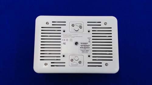
Click to zoom
Application Details
- Equipment Class
- DTS - Digital Transmission System
- Date of Grant
- Mar 09, 2015
- Application Purpose
- Original Equipment
- Date of Application
- Feb 11, 2015
- Equipment Note
- Wireless Access Point
- Frequency Range
- 2412.00000000 - 2462.00000000
- Country
- United States
Documents & Files
Document Text
Text extracted from the exhibit documents filed with the FCC. Open a document above to read the original.
Users Manual
data sheet Rugged indoor Aruba 228 wireless APs deliver gigabit Wi-Fi performance to 802.11ac mobile devices in harsh indoor environments such as warehouses and stadiums With a maximum data rate of 1.3 Gbps in the 5-GHz band and 600 Mbps in the 2.4-GHz band, 220 series APs are three-times faster than 802.11n APs and provide performance similar to a wired connection. The 228 APs include ClientMatch™ technology, which eliminates sticky cli ents by continuously gathering session performance metrics from mobile devices. This information is then used to steer each mobile device to the best AP and radio on the WLAN. Proactive and deterministic, ClientMatch dynamically optimizes Wi-Fi client performance as users roam and RF conditions change. If a mobile device moves out of range of an AP or RF interference impedes performance, ClientMatch automatically steers it to a better AP. With ClientMatch, 228 APs load web pages faster, deliver video streams with improved quality and support high densities of mobile devices. An 802.11ac network without ClientMatch performs no different than an 802.11n WLAN. The 228 APs additionally support priority handling and policy enforcement for individual Microsoft Lync media on the same device, including encrypted videoconferencing, voice, chat and desktop sharing. UniqUe benefits • Industrial design for rugged indoor environments - Extends temperature range for indoor environments that lack heating and cooling - Connect orized antenna ports support high gain large public venue antennas - Designed for enhanced physical security AR UBA 228 ACCESS POINT 802.11ac for rugged indoor locations •Delivers 1.9 Gbps aggregate throughput. -EtherChannel link aggregation on two Gigabit Ethernet ports provides 1.9 Gbps throughput. •600 Mbps in the 2.4-GHz band. -Supports up to 600 Mbps for TurboQAM-enabled mobile devices operating in the 2.4-GHz band – an industry first. •Best-in-class RF management -Integrated Adaptive Radio Management™ technology manages the 2.4-GHz and 5-GHz radio bands and ensures that APs stay clear of RF interference. •Spectrum analysis -Capable of part-time or dedicated air monitoring, the spectrum analyzer remotely scans the 2.4-GHz and 5-GHz radio bands to identify sources of RF interference. • Wireless mesh - Wireless mesh connections are convenient where Ethernet drops are not available. •Security -Integrated wireless intrusion protection offers threat protection and mitigation and eliminates the need for separate RF sensors and security appliances. -With an OpenDNS service subscription, Aruba Instant APs delivers integrated web filtering, malware and botnet protection to every device connected to the WLAN. -Encrypted IPsec VPN tunnels securely connect remote users to corporate network resources. -Integrated Trusted Platform Module (TPM) for secure storage of credentials and keys. -SecureJack-capable for secure tunneling of wired Ethernet traffic. data sheet ARUBA 228 ACCESS POINTS Choose yoUr operating mode The 228 APs offer a choice of operating modes to meet your u nique management and deployment requirements. • Controller-managed AP or Remote AP (RAP) running ArubaOS™. When managed by Aruba Mobility Controllers, 228 APs offer centralized configuration, data encryption, policy enforcement and network services, as well as distributed and centralized traffic forwarding. •Aruba Instant™ AP running InstantOS™. In Aruba Instant mode, a single AP automatically distributes the network configuration to other Instant APs in the WLAN. Simply power-up one Instant AP, configure it over the air, and plug in the other APs – the entire process takes about five minutes. • Spectrum analysis identifies sources of RF interference •Air monitor provides wireless intrusion protection •Hybrid AP serves Wi-Fi clients and provides wireless intrusion protection and spectrum analysis • Secure enterprise mesh For large installations across multiple sites, the Aruba Activate™ service significantly reduces deployment time by automating device provisioning, firmware upgrades, and inventory management. With Aruba Activate, Instant APs are factory- shipped to any site and configure themselves when powered up. If WLAN and network requirements change, a built-in migration path allows 228 Instant APs to become part of a WLAN that is centrally managed by a Mobility Controller. AP-228 SPECIFICATIONS - 2.4-GHz (600 Mbps max) and 5-GHz (1.3 Gbps max) radios, each with 3x3 MIMO and six external antenna connectors. Wireless radio speCifiCations •AP type: Indoor, dual radio, 5 GHz 802.11ac and 2.4 GHz 802.11n -In addition to 802.11n data rates, the 2.4-GHz radio supports 802.11ac data rates using 256-QAM modulation. This gives TurboQAM-enabled clients a 33% boost above the maximum supported data rate. • Software-configurable dual radio supports 5 GHz and 2.4 GHz •3x3 MIMO with three spatial streams and up to 1.3 Gbps wireless data rate •Supported frequency bands (country-specific restrictions apply): -2.4000 GHz to 2.4835 GHz -5.150 GHz to 5.250 GHz -5.250 GHz to 5.350 GHz -5.470 GHz to 5.725 GHz -5.725 GHz to 5.850 GHz • Available channels: Dependent upon configured regulatory domain •Dynamic frequency selection (DFS) optimizes the use of available RF spectrum •Supported radio technologies: -802.11b: Direct-sequence spread-spectrum (DSSS) -802.11a/g/n/ac: Orthogonal frequency-division multiplexing (OFDM) -802.11n/ac: 3x3 MIMO with up to three spatial streams •Supported modulation types: -802.11b: BPSK, QPSK, CCK -802.11a/g/n: BPSK, QPSK, 16-QAM, 64-QAM -802.11ac: BPSK, QPSK, 16-QAM, 64-QAM, 256-QAM • Transmit power: Configurable in increments of 0.5 dBm • Maximum (aggregate, conducted total) transmit power (limited by local regulatory requirements): - 2.4-GHz band: +28 dBm (23 dBm per chain) - 5-GHz bands: +28 dBm (23 dBm per chain) • Advanced cellular coexistence (ACC) feature to effectively deal with interference from cellular systems •Maximum ratio combining (MRC) for improved receiver…
Text truncated - open the document above for the full version.
Users Manual
AP-228 Wireless Access Point Installation Guide 0511728-02 |February 20151 The Aruba AP-228 is a fully temperature hardened, water resistant, indoor rated, dual-radio IEEE 802.11ac wireless access point. This access point use MIMO (Multiple-in, Multiple-out) technology and other high-throughput mode techniques to deliver high-performance, 802.11ac 2.4 GHz and 5 GHz functionality while simultaneously supporting existing 802.11a/b/g/n wireless services. The AP-228 access point works only in conjunction with an Aruba Controller. AP-228 Operations Wireless transceiver Wireless access point (IEEE 802.11 a/b/g/n/ac) Wireless air monitor (IEEE 802.11 a/b/g/n/ac) Protocol-independent networking functionality Compatibility with IEEE 802.3at PoE Central management configuration and upgrades with an Aruba Controller. Guide Overview “AP-228 Hardware Overview” on page 3 provides a detailed hardware overview of the AP-228. “Before You Begin” on page 5 provides key questions to ask and items to consider when deploying a wireless network. “Installing the AP” on page 7 describes the multi-step process for a successful installation and deployment of the AP-228. “Safety and Regulatory Compliance” on page 12 provides an overview of safety and regulatory compliance information. Package Contents AP-228 Access Point Cable Glands x2 USB Console Cable Copper Lug x1 M4 x 6 Screw x1 Installation Guide (this document) The weatherproof caps for Ethernet and Console interfaces are connected to the AP, not loose in the package. Mounting kits for use with the AP-228 access points are sold separately. Contact your Aruba sales representative for details. 2AP-228 Wireless Access Point| Installation Guide Inform your supplier if there are any incorrect, missing, or damaged parts. If possible, retain the carton, including the original packing materials. Use these materials to repack and return the unit to the supplier if needed. AP-228 Wireless Access Point| Installation Guide3 AP-228 Hardware Overview Figure 1 AP-228 Front View Figure 2 AP-228 Bottom View LED The AP-228 is equipped with one LED that indicates the system status of the AP. Table 1 AP-228 LED Meanings during Boot Up LEDColor/StateMeaning System LEDOffNo power to AP RedInitial power-up Green - FlashingAP booting Green - SteadyAP ready and 1000Mbps Ethernet link established. The LED turns off after 1200 seconds Green - Yellow, 6 seconds period AP ready and 10/100Mbps Ethernet link established. The LED turns off after 1200 seconds 2G0 2G1 2G2 5G0 5G1 5G2 LAN WAN Grounding Point USB Console Port, Reset button and LED 4AP-228 Wireless Access Point| Installation Guide Table 2 AP-228 LED Meanings during Operation USB Console Port The USB Micro-B console port allows you to connect the AP to a terminal or a laptop for direct local management. Use the included USB console cable to connect the AP. You can download the necessary driver for USB-UART adapter from support.arubanetworks.com under the Tools & Resources tab. Use the following setting to access the terminal: Ethernet Ports AP-228 is equipped with two10/100/1000Base-T (RJ-45) Gigabit Ethernet ports (WAN and LAN port) for wired network connectivity. The WAN port supports 802.3at Power over Ethernet (PoE), accepting 48 VDC (nominal) as a standard defined Powered Device (PD) from a Power Sourcing Equipment (PSE) such as a PoE midspan injector. These ports have RJ-45 female connectors with the pin-outs shown in Figure 3. Figure 3 Gigabit Ethernet Port Pin-Out Reset Button The reset button can be used to return the AP to factory default settings. To reset the AP: 1. Power off the AP. 2. Press and hold the reset button using a small, narrow object, such as a paperclip. 3. Power-on the AP without releasing the reset button. The system LED will flash within 5 seconds. 4. Release the reset button. The system LED will flash again within 15 seconds indicating that the reset is completed. The AP will now continue to boot with the factory default settings. LEDColor/StateMeaning System LEDSolid RedGeneral fault One blink off every 3 seconds Radio 0 fault (5 GHz) Two quick blink off 0.5 seconds apart cycled every 3 seconds Radio 1 fault (2.4GHz) Table 3 Console Settings Baud RateData BitsParityStop BitsFlow Control 96008None1 None 1000Base-T Gigabit Ethernet Port RJ-45 Female Pin-Out Signal Name 1 2 3 4 5 6 7 8 BI_DC+ BI_DC- BI_DD+ BI_DD- BI_DA+ BI_DA- BI_DB+ BI_DB- Function Bi-directional pair +C, POE Positive Bi-directional pair -C, POE Positive Bi-directional pair +D, POE Negative Bi-directional pair -D, POE Negative Bi-directional pair +A, POE Negative Bi-directional pair -A, POE Negative Bi-directional pair +B, POE Positive Bi-directional pair -B, POE Positive AP-228 Wireless Access Point| Installation Guide5 Grounding Point Always remember to protect the AP by installing grounding lines. The ground connection must be complete before connecting power to the AP enclosure. Figure 4 AP-228 Rear View Before You Begin Pre-Installation Network Requirements After WLAN planning is complete and the appropriate products and their placement have been determined, the Aruba controller(s) must be installed and initial setup performed before the Aruba APs are deployed. ! CAUTION FCC Statement: Improper termination of access points installed in the United States configured to non-US model controllers will be in violation of the FCC grant of equipment authorization. Any such willful or intentional violation may result in a requirement by the FCC for immediate termination of operation and may be subject to forfeiture (47 CFR 1.80). ! CAUTION EU Statement: Lower power radio LAN product operating in 2.4 GHz and 5 GHz bands. Please refer to the ArubaOS User Guide for details on restrictions. Produit réseau local radio basse puissance operant dans la bande fréquence 2.4 GHz et 5 GHz. Merci de vous referrer au ArubaOS User Guide pour les details des restrictions. Low Power FunkLAN Produkt, das im 2.4 GHz und im 5 GHz Band arbeit…
Text truncated - open the document above for the full version.
External Photos
FCC ID: Q9DAPIN0228 IC: 4675A-APIN0228 Page 1 of 4 External Picture FCC ID: Q9DAPIN0228 IC: 4675A-APIN0228 Page 2 of 4 FCC ID: Q9DAPIN0228 IC: 4675A-APIN0228 Page 3 of 4 FCC ID: Q9DAPIN0228 IC: 4675A-APIN0228 Page 4 of 4
ID Label/Location Info
LABEL,AGENCY,AP-228 COLOR OF BASE: MATERIAL PRIMARY COLOR OF FONT: BLACK 5. UL APPROVED INK & MATERIAL 401186501 制造商/製造商/Manufacturer: Aruba Networks,Inc 型号/型號/Model: APIN0228 产品名称/產品名稱/Product Name: 接入点/接入點/Access Point S/N: XXXXXXXXXXXXXX XXXXXXXXXXXX MAC: DOM PN MAC S/N ON LINE PRINTING AP-228 30 x 6mm 30 x 10mm 28 x 6mm 28 x 6mm 4011865-01
RF Exposure Info
FCC ID: Q9DAPIN0228 IC: 4675A-APIN0228 Page 1 of 2 Statement of compliance to Maximum Permissible Exposure (MPE) Applicant : Aruba Networks, Inc 1344 Crossman Ave. Sunnyvale, CA,94089 Product Name : Wireless Access Point Type/Model : APIN0228 According to §2.1091, §2.1093 and §1.1307(b), systems operating under the provisions of this section shall be operated in a manner that ensures that the public is not exposed to radio frequency energy level in excess of the Commission’s guidelines. The S = PG / (4πR²) Where S = power density in mW/cm² P = transmit power in mW G = numeric gain of transmit antenna (numeric gain=Log-1(dB antenna gain/10)) R = distance (cm) The calculations in the table below use the highest gain of antenna for client EUT. These calculations represent worst case in terms of the exposure levels. Frequency band Power Antenna Gain R S Limits (MHz) dBm mW dBi(Numeric) (cm)(mW/cm 2 ) (mW/cm 2 ) 2400 -2483.5 29.77 948 2.01.58 25 0.191 1 5150-5250 28.22 800 2.01.58 25 0.161 1 5725-5850 29.03 664 2.01.58 25 0.134 1 Frequency band Power Antenna Gain R S Limits (MHz) dBm mW dBi(Numeric) (cm)(mW/cm 2 ) (mW/cm 2 ) 2400 -2483.5 21.17 131 14 25.12 25 0.419 1 5150-5250 20.80 120 14 25.12 25 0.384 1 5725-5850 21.10 129 14 25.12 25 0.413 1 Note: 1 mW/cm 2 from 1.310 Table 1 For the device supporting simultaneous transmission of 2.4GHz and 5GHz, according to KDB447498 D01 General RF Exposure Guidance v05r02, the worst MPE = 0.419 + 0.413 = 0.832 mW/cm 2 < 1 mW/cm 2 . Date of issue: Jan. 23, 2015 Prepared by: Reviewed by: Wade Zhang (Project Engineer) Daniel Zhao (Reviewer) FCC ID: Q9DAPIN0228 IC: 4675A-APIN0228 Page 2 of 2 Appendix I Definition below must be outlined in the User Manual: To satisfy FCC RF exposure requirements, a separation distance of 25 cm or more should be maintained between the antenna of this device and persons during device operation. To ensure compliance, operations at closer than this distance is not recommended.
Test Report
FCC ID: Q9DAPIN0228 IC: 4675A-APIN0228 Page 1 of 74 A.1: Duty cycle Duty Cycle(2.4G band): 802.11b 802.11g FCC ID: Q9DAPIN0228 IC: 4675A-APIN0228 Page 2 of 74 802.11n20 802.11n40 FCC ID: Q9DAPIN0228 IC: 4675A-APIN0228 Page 3 of 74 A.2: Minimum 6dB Bandwidth Port 0: 802.11b-2412 802.11b-2437 FCC ID: Q9DAPIN0228 IC: 4675A-APIN0228 Page 4 of 74 802.11b-2462 802.11g-2412 FCC ID: Q9DAPIN0228 IC: 4675A-APIN0228 Page 5 of 74 802.11g-2437 802.11g-2462 FCC ID: Q9DAPIN0228 IC: 4675A-APIN0228 Page 6 of 74 802.11n20-2412 802.11n20-2437 FCC ID: Q9DAPIN0228 IC: 4675A-APIN0228 Page 7 of 74 802.11n20-2462 802.11n40-2422 FCC ID: Q9DAPIN0228 IC: 4675A-APIN0228 Page 8 of 74 802.11n40-2437 802.11n40-2452 FCC ID: Q9DAPIN0228 IC: 4675A-APIN0228 Page 9 of 74 Port 1 802.11b-2412 802.11b-2437 FCC ID: Q9DAPIN0228 IC: 4675A-APIN0228 Page 10 of 74 802.11b-2462 802.11g-2412 FCC ID: Q9DAPIN0228 IC: 4675A-APIN0228 Page 11 of 74 802.11g-2437 802.11g-2462 FCC ID: Q9DAPIN0228 IC: 4675A-APIN0228 Page 12 of 74 802.11n20-2412 802.11n20-2437 FCC ID: Q9DAPIN0228 IC: 4675A-APIN0228 Page 13 of 74 802.11n20-2462 802.11n40-2422 FCC ID: Q9DAPIN0228 IC: 4675A-APIN0228 Page 14 of 74 802.11n40-2437 802.11n40-2452 FCC ID: Q9DAPIN0228 IC: 4675A-APIN0228 Page 15 of 74 Port 2 802.11b-2412 802.11b-2437 FCC ID: Q9DAPIN0228 IC: 4675A-APIN0228 Page 16 of 74 802.11b-2462 802.11g-2412 FCC ID: Q9DAPIN0228 IC: 4675A-APIN0228 Page 17 of 74 802.11g-2437 802.11g-2462 FCC ID: Q9DAPIN0228 IC: 4675A-APIN0228 Page 18 of 74 802.11n20-2412 802.11n20-2437 FCC ID: Q9DAPIN0228 IC: 4675A-APIN0228 Page 19 of 74 802.11n20-2462 802.11n40-2422 FCC ID: Q9DAPIN0228 IC: 4675A-APIN0228 Page 20 of 74 802.11n40-2437 802.11n40-2452 FCC ID: Q9DAPIN0228 IC: 4675A-APIN0228 Page 21 of 74 A.3: Maximum Conducted Output power A.3.1:Mode 6 Port 0 802.11b-2412 802.11b-2437 FCC ID: Q9DAPIN0228 IC: 4675A-APIN0228 Page 22 of 74 802.11b-2462 802.11g-2412 FCC ID: Q9DAPIN0228 IC: 4675A-APIN0228 Page 23 of 74 802.11g-2437 802.11g-2462 FCC ID: Q9DAPIN0228 IC: 4675A-APIN0228 Page 24 of 74 802.11n20-2412 802.11n20-2437 FCC ID: Q9DAPIN0228 IC: 4675A-APIN0228 Page 25 of 74 802.11n20-2462 802.11n40-2422 FCC ID: Q9DAPIN0228 IC: 4675A-APIN0228 Page 26 of 74 802.11n40-2437 802.11n40-2452 FCC ID: Q9DAPIN0228 IC: 4675A-APIN0228 Page 27 of 74 Port 1 802.11b-2412 802.11b-2437 FCC ID: Q9DAPIN0228 IC: 4675A-APIN0228 Page 28 of 74 802.11b-2462 802.11g-2412 FCC ID: Q9DAPIN0228 IC: 4675A-APIN0228 Page 29 of 74 802.11g-2437 802.11g-2462 FCC ID: Q9DAPIN0228 IC: 4675A-APIN0228 Page 30 of 74 802.11n20-2412 802.11n20-2437 FCC ID: Q9DAPIN0228 IC: 4675A-APIN0228 Page 31 of 74 802.11n20-2462 802.11n40-2422 FCC ID: Q9DAPIN0228 IC: 4675A-APIN0228 Page 32 of 74 802.11n40-2437 802.11n40-2452 FCC ID: Q9DAPIN0228 IC: 4675A-APIN0228 Page 33 of 74 Port 2 802.11b-2412 802.11b-2437 FCC ID: Q9DAPIN0228 IC: 4675A-APIN0228 Page 34 of 74 802.11b-2462 802.11g-2412 FCC ID: Q9DAPIN0228 IC: 4675A-APIN0228 Page 35 of 74 802.11g-2437 802.11g-2462 FCC ID: Q9DAPIN0228 IC: 4675A-APIN0228 Page 36 of 74 802.11n20-2412 802.11n20-2437 FCC ID: Q9DAPIN0228 IC: 4675A-APIN0228 Page 37 of 74 802.11n20-2462 802.11n40-2422 FCC ID: Q9DAPIN0228 IC: 4675A-APIN0228 Page 38 of 74 802.11n40-2437 802.11n40-2452 FCC ID: Q9DAPIN0228 IC: 4675A-APIN0228 Page 39 of 74 A3.2:Mode 16 Port 0 802.11b-2412 802.11b-2437 FCC ID: Q9DAPIN0228 IC: 4675A-APIN0228 Page 40 of 74 802.11b-2462 802.11g-2412 FCC ID: Q9DAPIN0228 IC: 4675A-APIN0228 Page 41 of 74 802.11g-2437 802.11g-2462 FCC ID: Q9DAPIN0228 IC: 4675A-APIN0228 Page 42 of 74 802.11n20-2412 802.11n20-2437 FCC ID: Q9DAPIN0228 IC: 4675A-APIN0228 Page 43 of 74 802.11n20-2462 802.11n40-2422 FCC ID: Q9DAPIN0228 IC: 4675A-APIN0228 Page 44 of 74 802.11n40-2437 802.11n40-2452 FCC ID: Q9DAPIN0228 IC: 4675A-APIN0228 Page 45 of 74 Port 1 802.11b-2412 802.11b-2437 FCC ID: Q9DAPIN0228 IC: 4675A-APIN0228 Page 46 of 74 802.11b-2462 802.11g-2412 FCC ID: Q9DAPIN0228 IC: 4675A-APIN0228 Page 47 of 74 802.11g-2437 802.11g-2462 FCC ID: Q9DAPIN0228 IC: 4675A-APIN0228 Page 48 of 74 802.11n20-2412 802.11n20-2437 FCC ID: Q9DAPIN0228 IC: 4675A-APIN0228 Page 49 of 74 802.11n20-2462 802.11n40-2422 FCC ID: Q9DAPIN0228 IC: 4675A-APIN0228 Page 50 of 74 802.11n40-2437 802.11n40-2452
Test Report
FCC ID: Q9DAPIN0228 IC: 4675A-APIN0228 Page 1 of 90 B.1: Emissions in non-restricted frequency band Port 0 802.11b-2412-1 802.11b-2412-2 FCC ID: Q9DAPIN0228 IC: 4675A-APIN0228 Page 2 of 90 802.11b-2412-3 802.11b-2412-4 FCC ID: Q9DAPIN0228 IC: 4675A-APIN0228 Page 3 of 90 802.11b-2412-5 802.11b-2437-1 FCC ID: Q9DAPIN0228 IC: 4675A-APIN0228 Page 4 of 90 802.11b-2437-2 802.11b-2437-3 FCC ID: Q9DAPIN0228 IC: 4675A-APIN0228 Page 5 of 90 802.11b-2437-4 802.11b-2437-5 FCC ID: Q9DAPIN0228 IC: 4675A-APIN0228 Page 6 of 90 802.11b-2462-1 802.11b-2462-2 FCC ID: Q9DAPIN0228 IC: 4675A-APIN0228 Page 7 of 90 802.11b-2462-3 802.11b-2462-4 FCC ID: Q9DAPIN0228 IC: 4675A-APIN0228 Page 8 of 90 802.11b-2462-5 802.11g-2412-1 FCC ID: Q9DAPIN0228 IC: 4675A-APIN0228 Page 9 of 90 802.11g-2412-2 802.11g-2412-3 FCC ID: Q9DAPIN0228 IC: 4675A-APIN0228 Page 10 of 90 802.11g-2412-4 802.11g-2412-5 FCC ID: Q9DAPIN0228 IC: 4675A-APIN0228 Page 11 of 90 802.11g-2437-1 802.11g-2437-2 FCC ID: Q9DAPIN0228 IC: 4675A-APIN0228 Page 12 of 90 802.11g-2437-3 802.11g-2437-4 FCC ID: Q9DAPIN0228 IC: 4675A-APIN0228 Page 13 of 90 802.11g-2437-5 802.11g-2462-1 FCC ID: Q9DAPIN0228 IC: 4675A-APIN0228 Page 14 of 90 802.11g-2462-2 802.11g-2462-3 FCC ID: Q9DAPIN0228 IC: 4675A-APIN0228 Page 15 of 90 802.11g-2462-4 802.11g-2462-5 FCC ID: Q9DAPIN0228 IC: 4675A-APIN0228 Page 16 of 90 802.11n20-2412-1 802.11n20-2412-2 FCC ID: Q9DAPIN0228 IC: 4675A-APIN0228 Page 17 of 90 802.11n20-2412-3 802.11n20-2412-4 FCC ID: Q9DAPIN0228 IC: 4675A-APIN0228 Page 18 of 90 802.11n20-2412-5 802.11n20-2437-1 FCC ID: Q9DAPIN0228 IC: 4675A-APIN0228 Page 19 of 90 802.11n20-2437-2 802.11n20-2437-3 FCC ID: Q9DAPIN0228 IC: 4675A-APIN0228 Page 20 of 90 802.11n20-2437-4 802.11n20-2437-5 FCC ID: Q9DAPIN0228 IC: 4675A-APIN0228 Page 21 of 90 802.11n20-2462-1 802.11n20-2462-2 FCC ID: Q9DAPIN0228 IC: 4675A-APIN0228 Page 22 of 90 802.11n20-2462-3 802.11n20-2462-4 FCC ID: Q9DAPIN0228 IC: 4675A-APIN0228 Page 23 of 90 802.11n20-2462-5 802.11n40-2422-1 FCC ID: Q9DAPIN0228 IC: 4675A-APIN0228 Page 24 of 90 802.11n40-2422-2 802.11n40-2422-3 FCC ID: Q9DAPIN0228 IC: 4675A-APIN0228 Page 25 of 90 802.11n40-2422-4 802.11n40-2422-5 FCC ID: Q9DAPIN0228 IC: 4675A-APIN0228 Page 26 of 90 802.11n40-2437-1 802.11n40-2437-2 FCC ID: Q9DAPIN0228 IC: 4675A-APIN0228 Page 27 of 90 802.11n40-2437-3 802.11n40-2437-4 FCC ID: Q9DAPIN0228 IC: 4675A-APIN0228 Page 28 of 90 802.11n40-2437-5 802.11n40-2452-1 FCC ID: Q9DAPIN0228 IC: 4675A-APIN0228 Page 29 of 90 802.11n40-2452-2 802.11n40-2452-3 FCC ID: Q9DAPIN0228 IC: 4675A-APIN0228 Page 30 of 90 802.11n40-2452-4 802.11n40-2452-5 FCC ID: Q9DAPIN0228 IC: 4675A-APIN0228 Page 31 of 90 Port 1 802.11b-2412-1 802.11b-2412-2 FCC ID: Q9DAPIN0228 IC: 4675A-APIN0228 Page 32 of 90 802.11b-2412-3 802.11b-2412-4 FCC ID: Q9DAPIN0228 IC: 4675A-APIN0228 Page 33 of 90 802.11b-2412-5 802.11b-2437-1 FCC ID: Q9DAPIN0228 IC: 4675A-APIN0228 Page 34 of 90 802.11b-2437-2 802.11b-2437-3 FCC ID: Q9DAPIN0228 IC: 4675A-APIN0228 Page 35 of 90 802.11b-2437-4 802.11b-2437-5 FCC ID: Q9DAPIN0228 IC: 4675A-APIN0228 Page 36 of 90 802.11b-2462-1 802.11b-2462-2 FCC ID: Q9DAPIN0228 IC: 4675A-APIN0228 Page 37 of 90 802.11b-2462-3 802.11b-2462-4 FCC ID: Q9DAPIN0228 IC: 4675A-APIN0228 Page 38 of 90 802.11b-2462-5 802.11g-2412-1 FCC ID: Q9DAPIN0228 IC: 4675A-APIN0228 Page 39 of 90 802.11g-2412-2 802.11g-2412-3 FCC ID: Q9DAPIN0228 IC: 4675A-APIN0228 Page 40 of 90 802.11g-2412-4 802.11g-2412-5 FCC ID: Q9DAPIN0228 IC: 4675A-APIN0228 Page 41 of 90 802.11g-2437-1 802.11g-2437-2 FCC ID: Q9DAPIN0228 IC: 4675A-APIN0228 Page 42 of 90 802.11g-2437-3 802.11g-2437-4 FCC ID: Q9DAPIN0228 IC: 4675A-APIN0228 Page 43 of 90 802.11g-2437-5 802.11g-2462-1 FCC ID: Q9DAPIN0228 IC: 4675A-APIN0228 Page 44 of 90 802.11g-2462-2 802.11g-2462-3 FCC ID: Q9DAPIN0228 IC: 4675A-APIN0228 Page 45 of 90 802.11g-2462-4 802.11g-2462-5 FCC ID: Q9DAPIN0228 IC: 4675A-APIN0228 Page 46 of 90 802.11n20-2412-1 802.11n20-2412-2 FCC ID: Q9DAPIN0228 IC: 4675A-APIN0228 Page 47 of 90 802.11n20-2412-3 802.11n20-2412-4 FCC ID: Q9DAPIN0228 IC: 4675A-APIN0228 Page 48 of 90 802.11n20-2412-5 802.11n20-2437-1 FCC ID: Q9DAPIN0228 IC: 4675A-APIN0228 Page 49 of 90 802.11n20-2437-2 802.11n20-2437-3 FCC ID: Q9DAPIN0228 IC: 4675A-APIN0228 Page 50 of 90 802.11n20-2437-4 802.11n20-2437-5
Test Report
FCC ID: Q9DAPIN0228 IC: 4675A-APIN0228 Page 1 of 44 TTRF15Ea/effective date: Dec. 15 th , 2013 RF TEST REPORT for Intentional Radiator No. 150101400SHA-001 Applicant :Aruba Networks, Inc 1344 Crossman Ave. Sunnyvale, CA,94089 Manufacturer :Aruba Networks, Inc 1344 Crossman Ave. Sunnyvale, CA,94089 Product Name :Access Point Type/Model :APIN0228 SUMMARY The equipment complies with the requirements according to the following standard(s): 47CFR Part 15 (2014): Radio Frequency Devices ANSI C63.4 (2003): American National Standard for Methods of Measurement of Radio-Noise Emissions from Low-Voltage Electrical and Electronic Equipment in the Range of 9 kHz to 40 GHz Date of issue: Jan 23, 2015 Prepared by: Reviewed by: Wade Zhang (Project Engineer) Daniel Zhao (Reviewer) FCC ID: Q9DAPIN0228 IC: 4675A-APIN0228 Page 2 of 44 TTRF15Ea/effective date: Dec. 15 th , 2013 Description of Test Facility Name: Intertek Testing Services Limited Shanghai Address: Building No.86, 1198 Qinzhou Road(North), Shanghai 200233, P.R. China FCC Registration Number: 236597 IC Assigned Code: 2042B-1 Name of contact: Jonny Jing Tel: +86 21 61278271 Fax: +86 21 54262353 FCC ID: Q9DAPIN0228 IC: 4675A-APIN0228 Page 3 of 44 TTRF15Ea/effective date: Dec. 15 th , 2013 Content SUMMARY .......................................................................................................................................................... 1 DESCRIPTION OF TEST FACILITY ......................................................................................................................... 2 1. TEST SUMMARY .......................................................................................................................................... 4 2. GENERAL INFORMATION ............................................................................................................................ 5 2.1 Applicant Information ............................................................................................... 5 2.2 Identification of the EUT .......................................................................................... 5 2.3 Technical specification ............................................................................................. 6 3. TEST SPECIFICATION .................................................................................................................................. 9 3.1 Instrument list ........................................................................................................... 9 3.2 Test Standard ............................................................................................................ 9 3.3 Mode of operation during the test / Test peripherals used ...................................... 10 3.4 Data rate VS Power ................................................................................................. 13 3.5 Duty cycle ............................................................................................................... 13 4. MINIMUM 6DB BANDWIDTH ..................................................................................................................... 14 4.1 Limit ........................................................................................................................ 14 4.2 Test Configuration .................................................................................................. 14 4.3 Test Procedure and test setup .................................................................................. 14 4.4 Test Protocol ........................................................................................................... 15 5. MAXIMUM CONDUCTED OUTPUT POWER ................................................................................................ 16 5.1 Test limit ................................................................................................................. 16 5.2 Test Configuration .................................................................................................. 16 5.3 Test procedure and test setup .................................................................................. 17 5.4 Test protocol ........................................................................................................... 18 6. POWER SPECTRUM DENSITY ..................................................................................................................... 19 6.1 Test limit ................................................................................................................. 19 6.2 Test Configuration .................................................................................................. 19 6.3 Test procedure and test setup .................................................................................. 20 6.4 Test Protocol ........................................................................................................... 21 7. EMISSIONS IN NON-RESTRICTED FREQUENCY BANDS............................................................................... 22 7.1 Test limit ................................................................................................................. 22 7.2 Test Configuration .................................................................................................. 22 7.3 Test procedure and test setup .................................................................................. 22 7.4 Test Protocol ........................................................................................................... 24 8. RADIATED EMISSIONS IN RESTRICTED FREQUENCY BANDS ..................................................................... 25 8.1 Test limit ................................................................................................................. 25 8.2 Test Configuration .................................................................................................. 25 8.3 Test …
Text truncated - open the document above for the full version.
Test Setup Photos
FCC ID: Q9DAPIN0228 IC: 4675A-APIN0228 Page 1 of 8 Test Setup FCC ID: Q9DAPIN0228 IC: 4675A-APIN0228 Page 2 of 8 1. Radiated Emission Below 1GHz(2G Mode) Above 1GHz (2G Mode) FCC ID: Q9DAPIN0228 IC: 4675A-APIN0228 Page 3 of 8 Below 1GHz(5G Mode) Above 1GHz (5G Mode) FCC ID: Q9DAPIN0228 IC: 4675A-APIN0228 Page 4 of 8 2. Conducted Emission Front (2G Mode) Back (2G Mode) FCC ID: Q9DAPIN0228 IC: 4675A-APIN0228 Page 5 of 8 Front (5G Mode) Back (5G Mode) FCC ID: Q9DAPIN0228 IC: 4675A-APIN0228 Page 6 of 8 3. Conducted Test (2G Mode) FCC ID: Q9DAPIN0228 IC: 4675A-APIN0228 Page 7 of 8 (5G Mode) FCC ID: Q9DAPIN0228 IC: 4675A-APIN0228 Page 8 of 8
Contact Information
Applicant
Mark Hill(Principal Engineer)
Technical Contact
Intertek Testing Services Limited ShanghaiDaniel Zhao
[email protected]86 21 61278269
Building No.86, 1198 Qinzhou Road(North) · Shanghai · China
Test Firm
Intertek Testing Services Limited ShanghaiJonny Jing
Technical Specifications
| # | Rule Parts | Frequency Range | Power Output |
|---|---|---|---|
| 1 | 15C | 2.41 GHz - 2.46 GHz | 948.00 mW |
Other Applications from Hewlett Packard Enterprise Company
Q9DAPINH721
Jul 17, 2026Access Point
Equipment Class
6ID - 15E 6 GHz Low Power Indoor Access PointQ9DASIN0307
Dec 22, 2025HPE Aruba User Experience Sensor
Equipment Class
DTS - Digital Transmission SystemQ9DASIN0308
Nov 23, 2025HPE Aruba User Experience Sensor
Equipment Class
DTS - Digital Transmission SystemQ9DAPEX0764
Nov 20, 2025ACCESS POINT
Equipment Class
DTS - Digital Transmission SystemQ9DAPIN0763
Sep 29, 2025ACCESS POINT
Equipment Class
NII - Unlicensed National Information Infrastructure TX