Q9DAPIN0324325Wireless Access Point
Hewlett Packard Enterprise Company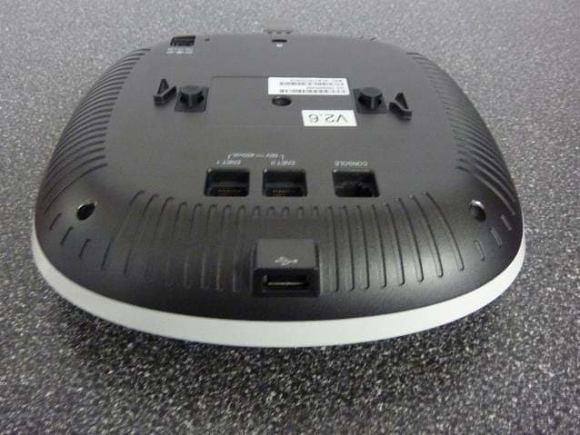
Click to zoom
Application Details
- Equipment Class
- DTS - Digital Transmission System
- Date of Grant
- Jul 20, 2015
- Application Purpose
- Original Equipment
- Date of Application
- Jul 15, 2015
- Equipment Note
- Wireless Access Point
- Frequency Range
- 2422.00000000 - 2452.00000000
- Country
- United States
Documents & Files
Document Text
Text extracted from the exhibit documents filed with the FCC. Open a document above to read the original.
Users Manual
Aruba 320 Series Wireless Access Point Installation Guide The Aruba 320 Series Wireless Access Points support IEEE 802.11ac standards for high-performance WLAN, and is equipped with two dual-band radios, which can provide access and monitor the network simultaneously. Multi-user Multiple-in, Multiple-output (MU-MIMO) technology allows this access point to deliver high-performance 802.11n 2.4 GHz and 802.11ac 5 GHz functionality, while also supporting 802.11a/b/g wireless services. The AP-324 and AP-325 access points work in conjunction with an Aruba controller, while the IAP-324 and IAP-325 access points can be configured using a built-in virtual controller. The 320 Series Wireless Access Points provide the following capabilities: Dual wireless transceiver IEEE 802.11a/b/g/n/ac operation as a wireless access point IEEE 802.11a/b/g/n/ac operation as a wireless air monitor Compatibility with IEEE 802.3at and 802.3af PoE Centralized management configuration and upgrades Integrated Bluetooth Low Energy (BLE) radio Package Contents (I)AP-324 or (I)AP-325 access point 9/16" and 15/16” Ceiling Rail Adapters Regulatory Compliance and Safety Information Guide Instant Quick Start Guide (for Instant access points only) Professional Install Guide (for (I)AP-324 only) Installation guide (this document) Software The AP-324 and AP-325 require ArubaOS 6.4.4 or higher. For additional information, refer to the ArubaOS User Guide and ArubaOS Quick Start Guide. The IAP-324 and IAP-325 require Aruba Instant 4.2.1 or higher. For additional information, please refer to the Aruba Instant User Guide or the Aruba Instant Quick Start Guide. 320 Series Hardware Overview Figure 1 LEDs LEDs The 320 Series access points have two LEDs that indicate the system and radio status of the device. . External Antenna Connectors The (I)AP-324 access points are equipped with four external antenna connectors located on the front corners of the access point (see Figure 2). Figure 2 External Antenna Connectors for the (I)AP-324 USB Interface The 320 Series is equipped with a USB port for connectivity with cellular modems and other USB client devices. When powered by an 802.3at or DC source the USB port can supply up to 5W. Figure 3 Bottom Panel Console Port The serial console port allows the user to connect the access point to a serial terminal or a laptop for direct local management. This port is an RJ-45 connector, with pinouts details in Figure 4. Connect it directly to a terminal or terminal server using an Ethernet cable. Figure 4 Serial Port Pin-Out Ethernet Ports The 320 Series is equipped with two 10/100/1000 Base-T (RJ-45) auto-sensing, MDI/MDX wired-network connectivity port. These ports support IEEE 802.3af and 802.3at Power over Ethernet (PoE) compliant sources, accepting 56V DC (nominal) as a standard defined Powered Device (PD) from a Power Sourcing Equipment (PSE), such as a PoE midspan injector, or network infrastructure that supports PoE. The 10/100/1000 Mbps Ethernet ports are on the bottom of the access point. These ports have RJ-45 female connectors with the pin-outs shown in Figure 5. Figure 5 Gigabit Ethernet Port Pin-Out Kensington Lock Slot The 320 Series is equipped with a Kensington lock slot for additional security. Reset Button The reset button can be used to return the access point to factory default settings. To reset the access point, refer to the steps below: 1. Power off the access point. 2. Press and hold the reset button using a small, narrow object, such as a paperclip. 3. Power-on the access point without releasing the reset button. The power LED will flash within 5 seconds. 4. Release the reset button. The power LED will flash again within 15 seconds indicating that the reset is completed. The access point will now continue to boot with the factory default settings. Power The E0 and E1 port support PoE-in, allowing one port to draw power from an 802.3at (recommended) or an 802.3af source. When both PoE and DC power sources are available, the access point will default to using the DC power source. If PoE is not available, the 320 Series has a single 12V/30W DC power jack socket to support the AP-AC-12V30UN AC-to-DC adapter kit (sold separately). Power Modes The 320 Series can operate in two power modes. The modes are not configurable and are determined by the access point based on the amount of power available. The 320 Series Wireless Access Points operate without restrictions when powered by a DC or 802.3at PoE source. When powered by an 802.3af PoE source, the following restrictions apply: Second Ethernet port disabled USB interface disabled 2.4 GHz in 1x1:1 mode Before You Begin Access Point Pre-Installation Checklist Before installing your 320 Series access point, ensure that you have the following: CAT5E or CAT6 UTP cable of required length One of the following power sources: IEEE 802.3at or 802.3af-compliant Power over Ethernet (PoE) source. The PoE source can be any power source equipment (PSE) controller or midspan PSE device Aruba APAC-DC adapter kit (sold separately) For AP-324 and AP-325 only: Aruba Controller provisioned on the network: Layer 2/3 network connectivity to your access point One of the following network services: Aruba Discovery Protocol (ADP) DNS server with an “A” record DHCP Server with vendor-specific options. Verifying Pre-Installation Connectivity Before installing access points in a network environment, make sure that they are able to locate and connect to the controller after power on. Specifically, you must verify the following conditions: When connected to the network, each access point is assigned a valid IP address Access points are able to locate the controller ! CAUTION This device must be professionally installed and serviced by a trained ACMP or similar Aruba-certified technician. Aruba access points are classified as radio transmission devices, and are subject to government regulations of the host country. The network administr…
Text truncated - open the document above for the full version.
Users Manual
Aruba 320 Series Wireless Access Point Regulatory Compliance and Safety Information Guide 0511817-04 | July 20151 Introduction This document contains domestic and international regulatory compliance and safety information for 320 Series access points. To ensure that this device complies with the regulatory standards for your region, please refer to the sections below. Electrical and Environmental Specifications Regulatory Information Proper Disposal of Aruba Equipment Electrical and Environmental Specifications For additional specifications on this product, please refer to the product data sheet at www.arubanetworks.com/ safety_addendum. Electrical Ethernet: 2x 10/100/1000 Base-T auto-sensing Ethernet RJ-45 interface (E0-E1) Maximum power consumption (excluding USB): 20W (PoE) or 18.5W (DC) IEEE 802.3 (10 Base-T), IEEE 802.3u (100 Base-T). IEEE 802.3ab (1000 Base-T) Power over Ethernet (IEEE 802.3at or 802.3af complaint), 48VDC or 53VDC (nominal) and 57VDC/350mA (maximum). Power: 12VDC power interference, support powering through an AC-to-DC power adapter (AP-AC-12V30UN) Maximum power consumption (excluding USB):20W (PoE) or 18.5W (DC) Environmental Operating: Temperature: 0°C to +50°C (+32°F to +122°F) Humidity: 5% to 95% non-condensing Storage and transport: Temperature: -40°C to +70°C (40°F to +158°F) ! All Aruba access points should be professionally installed by an Aruba Certified Mobility Professional (ACMP). The installer is responsible for ensuring that grounding is available and meets applicable national and electrical codes. ! Tous les points d'accès Aruba doivent impérativement être installés par un professionnel agréé. Ce dernier doit s'assurer que l'appareil est mis à la terre et que le circuit de mise à la terre est conforme aux codes électriques nationaux en vigueur. If a power adapter other than the Aruba-approved adapter is used in the US or Canada, it should be NRTL listed, without an output rated 12VDC, minimum 2A, marked “LPS” and “Class 2”, and suitable for plugging into a standard power receptacle in the US and Canada. 2 Aruba 320 Series Wireless Access Point | Regulatory Compliance and Safety Information Guide Regulatory Information Aruba Networks provides a multi-language document that contains country-specific restrictions and additional safety and regulatory information for all Aruba access points. This document can be viewed or downloaded at www.arubanetworks.com. FCC FCC Class B Part 15 This equipment has been tested and found to comply with the limits for a Class B digital device, pursuant to Part 15 of the FCC Rules. This equipment generates, uses and can radiate radio frequency energy and, if not installed and used in accordance with the manufacturer’s instructions, may cause interference harmful to radio communications. Operation is subject to the following conditions: This device may not cause harmful interference. This device must accept any interference received, including interference that may cause undesired operation. If this equipment does cause interference, which can be determined by turning the equipment off and on, the user is encouraged to try to correct the interference by one or more of the following measures: Reorient or relocate the receiving antenna. Increase the separation between the equipment and receiver. Connect the equipment to an outlet on a circuit different from that to which the receiver is connected. Consult the dealer or an experienced radio or TV technician for help. Complies with the Class B limits for radio noise emissions as set out in the interference-causing equipment standard entitled “Digital Apparatus,” ICES-003 of Industry Canada. Users are advised that high power Radars are allocated as primary users of the bands 5250-5350 MHz and 5650-5850 MHz and these Radars could cause interference and/or damage to Licensed Exempt WLAN devices. Canada Complies with the Class B limits for radio noise emissions as set out in the interference-causing equipment standard entitled “Digital Apparatus,” ICES-003 of Industry Canada. Under Industry Canada regulations, this radio transmitter may only operate using an antenna of a type and maximum (or lesser) gain approved for the transmitter by Industry Canada. To reduce potential radio interference to other users, the antenna type and its gain should be so chosen that the equivalent isotropically radiated power (E.I.R.P.) does not exceed the limit necessary for successful communication. This device complies with Industry Canada license-exempt RSS standard(s). Operation is subject to the following two conditions: (1) this device may not cause interference, and (2) this device must accept any interference, including interference that may cause undesired operation of the device. ! RF Radiation Exposure Statement: This equipment complies with FCC RF radiation exposure limits. This equipment should be installed and operated with a minimum distance of 10.63 inches (27cm) between the radiator and your body for 2.4 GHz and 5 GHz operations. This transmitter must not be co-located or operating in conjunction with any other antenna or transmitter. When operated in 5.15 to 5.25 GHz frequency range, this device is restricted to indoor use to reduce the potential for harmful interference with co-channel Mobile Satellite Systems. ! Déclaration sur les limites d'exposition aux radiofréquences : cet équipement est conforme aux limites d'exposition aux rayonnements radioélectriques spécifiées par la FCC. Il doit être installé et utilisé à une distance minimale de 27 cm par rapport à votre corps pour les fréquences de 2,4 et 5 GHz. Cet émetteur-récepteur ne doit pas être utilisé ou situé à proximité d'autres antennes ou émetteurs-récepteurs. En cas d'utilisation dans la plage de fréquences de 5,15 à 5,25 GHz, cet appareil doit uniquement être utilisé en intérieur afin de réduire les risques d'interférence avec les systèmes satellites mobiles partageant le même canal. ! Changes or modif…
Text truncated - open the document above for the full version.
Cover Letter(s)
! Request!for!Confidentiality! ! Date:!July!13,!2015! ! Subject:!!Confidentiality!Request!for:!FCC!ID:!Q9DAPIN0324325;!IC:!4675AJAPIN0324325! ! Pursuant!to!FCC!47!CRF!0.457(d)!and!0.459!and!IC!RSPJ100,!Section!10,!the!applicant!requests!that!a! part!of!the!subject!FCC!application!be!held!confidential.!!! ! Type!of!Confidentiality!Requested!Exhibit! !Short!Term!Permanent!Block!Diagrams! !Short!Term!!Permanent!External!Photos! !!Short!Term!!Permanent* 1 !Internal!Photos! !Short!Term!!Permanent!Operation!Description/Theory!of!Operation! !Short!Term!!Permanent!Parts!List!&!Placement/BOM! !Short!Term!!Permanent!TuneJUp!Procedure! !Short!Term!!!Permanent!Schematics! !Short!Term!!Permanent!Test!Setup!Photos! !Short!Term!!Permanent*!User’s!Manual! ! Aruba!Networks,!Inc.!has!spent!substantial!effort!in!developing!this!product!and!it!is!one!of!the!first! of!its!kind!in!industry.!Having!the!subject!information!easily!available!to!"competition"!would!negate! the!advantage!they!have!achieved!by!developing!this!product.!Not!protecting!the!details!of!the!design! will!result!in!financial!hardship.!!!!! ! Permanent!Confidentiality:! The!applicant!requests!the!exhibits!listed!above!as!permanently!confidential!be!permanently! withheld!from!public!review!due!to!materials!that!contain!trade!secrets!and!proprietary!information! not!customarily!released!to!the!public.! ! Short<Term!Confidentiality:! The!applicant!requests!the!exhibits!selected!above!as!short!term!confidential!be!withheld!from!public! view!for!a!period!of!!!!180!!!!!days!from!the!date!of!the!Grant!of!Equipment!Authorization!and!prior!to! marketing.!!This!is!to!avoid!premature!release!of!sensitive!information!prior!to!marketing!or!release! of!the!product!to!the!public.!!Applicant!is!also!aware!that!they!are!responsible!to!notify!ACB!in!the! event!information!regarding!the!product!or!the!product!is!made!available!to!the!public.!!ACB!will!then! release!the!documents!listed!above!for!public!disclosure!pursuant!to!FCC!Public!Notice!DA!04J1705.! ! ! ! 1 - The asterisked items (*) require further justification before permanent confidentiality will be allowed. These also currently require review by the FCC under their Permit-But-Ask policy before the grant is issued and can delay completion of an application. Further justification should be added to the note above. One such example for a potted device would be: “The EUT is FULLY potted using a non-removable epoxy based material. Removal of potting material causes irreparable damage to internal circuitry. See photographs exhibits that outline the device before and after potting.” ! NOTE!for!Industry!Canada!Applications:! The!applicant!understands!that!until!such!time!that!IC!distinguishes!between!Short!Term!and! Permanent!Confidentiality,!either!type!of!marked!exhibit!above!will!simply!be!marked!Confidential! when!submitted!to!IC.! ! Sincerely,! ! By:!__________________________!!!!!!!Robert!Hastings:!Regulatory!Compliance!Manager! !!!!!!!!!!!!(Signature/Title 2 )!!!!(Print!name)! 2 - Must be signed by applicant contact given for applicant on the FCC site, or by the authorized agent if an appropriate authorized agent letter has been provided. Letters should be placed on appropriate letterhead.
Cover Letter(s)
Authority to Act as Agent Date: 05/04/2015 Aruba Networks 1344 Crossman Ave Sunnyvale, CA 940889 To Whom It May Concern: I appoint TUV Rheinland of North America, Inc, to act as our agent in the preparation of this application for equipment certification. I certify that submitted documents properly describe the device or system for which equipment certification is sought. I also certify that each unit manufactured, imported or marketed, as defined in the FCC or Industry Canada’s regulations will have affixed to it a label identical to that submitted for approval with this application. For instances where our authorized agent signs the application for certification on our behalf, I acknowledge that all responsibility for complying with the terms and conditions for Certification, as specified by TUV Rheinland Group, still resides with Aruba Networks 1344 Crossman Ave. Sunnyvale, CA 94089. For TCB applications, We certify that we are not subject to denial of federal benefits, that includes FCC benefits, pursuant to Section 5301 of the Anti-Drug Abuse Act of 1988, 21 U.S.C. 862. Further, no party, as defined in 47 CFR 1.2002 (b), to the application is subject to denial of federal benefits, that includes FCC benefits. Thank you, Agency Agreement Expiration Date: _____(December 31, 2015)_____ By: __________________________ Robert Hastings (Signature) (Print name) Title: Manager Regulatory Compliance Telephone: _408.227.4500 . On behalf of: Aruba Networks . (Company Name)
External Photos
TUV Rheinland Of North America 1279 Quarry Lane, Ste. A, Pleasanton, CA 95466 Tel: (925) 249‐9123, Fax: (925) 249‐9124 External Photos Page 1of4 Aruba Networks FCC ID: Q9DAPIN0324325, IC: 4675A‐APIN0324325 External Photos AIIN0325 TUV Rheinland Of North America 1279 Quarry Lane, Ste. A, Pleasanton, CA 95466 Tel: (925) 249‐9123, Fax: (925) 249‐9124 External Photos Page 2of4 Aruba Networks FCC ID: Q9DAPIN0324325, IC: 4675A‐APIN0324325 For Internal Antennas of this unit see internal Photos Exhibit TUV Rheinland Of North America 1279 Quarry Lane, Ste. A, Pleasanton, CA 95466 Tel: (925) 249‐9123, Fax: (925) 249‐9124 External Photos Page 3of4 Aruba Networks FCC ID: Q9DAPIN0324325, IC: 4675A‐APIN0324325 APIN0324 4 Antenna ports TUV Rheinland Of North America 1279 Quarry Lane, Ste. A, Pleasanton, CA 95466 Tel: (925) 249‐9123, Fax: (925) 249‐9124 External Photos Page 4of4 Aruba Networks FCC ID: Q9DAPIN0324325, IC: 4675A‐APIN0324325 BLE Antenna Location
ID Label/Location Info
REVISIONS DESCRIPTIONREV DATE APPROVED 1 OF 2 2/1 DRAWN APVD 0.1mm 0.5mm 1mm A3 印刷尺寸公差 其他 20 Park Avenue II, Hsinchu Science Park, Hsinchu 308, Taiwan, R.O.C. Tel: 886-3-6667799 Fax: 886-3-5788726 NOTES: 1. MATERIAL: PC/8B35, t=0.254 mm, 2. ADHESIVE: 3M 467膠,t=0.05 mm 3.刀模尺寸見第二頁 PART NUMBERCOLOR 1COLOR 2 PANTONE BLACK C PANTONE COOL GRAY 3 C COLOR 1 COLOR 2 SANDY CHEN RELEASEA 05/04/15 SANDY CHEN HSINYUN LIN 05/04/15 05/04/15 A NAMEPLATE, 4011929-01, AP-324, RVAQ-A1 3NRVAQA01P1-211 60.40 41.40 R 0.80 C 1.28 1.0 1.2 3NRVAQA01P1-211 n9.88 1 OF 2 2/1 DRAWN APVD 0.1mm 0.5mm 1mm A3 印刷尺寸公差 其他 20 Park Avenue II, Hsinchu Science Park, Hsinchu 308, Taiwan, R.O.C. Tel: 886-3-6667799 Fax: 886-3-5788726 PART NUMBERCOLOR 1COLOR 2 DIE CUT FRONTBACK 60.40 41.40 R 0.80 n9.88 C 1.28
Internal Photos
! ! ! ! ! ! ! ! ! ! ! ! ! ! Internal!&!External!Photo’s!! ! Model:!AP5324!&!AP5325! ! ! ! ! ! ! ! ! ! ! ! ! ! AP5 324! ! ! ! AP5 325!! ! Bottom!of!AP! ! ! AP5 325!Cover!Removed! ! AP5 324!Cover!Removed! ! ! ! ! ! ! ! ! AP5 324!Bottom!View! ! ! AP5 325!Bottom!View! ! View!under!Antenna!Plate! ! Top!View!of!Mai n!Baord!PCB! ! ! Main!Board!with!Shield!Removed!(BLE!section!Labeled)! ! ! Close5Up!Main!Board!CPU!Shield!Removed! ! ! Bottom!View!of!the!Main!Board!PCB!with!Shield! ! ! Bottom!View!of!the!Main!Board!with!Shields!Removed! ! ! Radio!Cards!Removed!! ! Radio!Cards!removed,!CPU!Shield!Removed! ! ! Close5Up!Main!Board!CPU!Shield!Removed!! ! BlueTooth!Section!(Shield!Removed)! ! ! AP5 324!5GHz!RF!Chip!(Top)! ! AP5 324!5GHz!Card!(Shield!Removed)! ! ! AP5 324!5GHz!Card!(Bottom)! ! ! AP5 324!5GHz!Card!Bottom!(Plate!Removed)! ! ! AP5 325!5GHz!C ard!(Top)! ! ! AP5 325!5GHz!Card!(Top!–!Shield!Removed)! ! ! AP5 325!5GHz!Card!(Bottom)! ! ! AP5 325!5GHz!Card!(Bottom!–!Plate!Removed)! ! ! 2.4GHz!Card!(Top!View)! Note:!Same!card!used!in!the!AP5324!&!AP5325! ! ! 2.4GHz!Card!(Top!–!Shield!Removed)!! Note:!Same!card!used!in!the!AP5324!&!AP5325! ! ! 2.4Ghz!Card!(Bottom!View)!! Note:!Same!card!used!in!the!AP5324!&!AP5325! ! ! 2.4GHz!Card!(Bottom!–!Plate!Removed)!! Note:!Same!card!used!in!the!AP5324!&!AP5325! ! ! ! ! ! !
RF Exposure Info
TUV Rheinland Of North America 1279 Quarry Lane, Ste. A, Pleasanton, CA 95466 Tel: (925) 249‐9123, Fax: (925) 249‐9124 RF Exposure Exhibi t Page1of4 Aruba Networks FCC ID: Q9DAPIN0324325,IC:4675A‐APIN0324325 Maximum Permissible Exposure 1.1 Maximum Permissible Exposure Test Methodology In this document, we try to prove the safety of radiation harmfulness to the human body for the product under test. The limit for Maximum Permissible Exposure (MPE) specified in FCC 1.1310 and Industry Canada RSS ‐102 were followed. The Gain of the antenna used in this calculation is declared by the manufacturer, and the maximum total power input to the antenna is measured. Through the Friis transmission formula and the maximum gain of the antenna, we can calculate the distance, away from the product, where the limit of MPE is reached. Although the Friis transmission formula is a far field assumption, the calculated result of that is an over‐prediction for near field power density. We will take that as the worst case to specify the safety range. RF Exposure Limit According to FCC 1.1310 table 1: The criteria listed in the following table shall be used to evaluate the environmental impact of human exposure to radio‐frequency (RF) radiation as specified in 1.1307(b) LIMITS FOR MAXIMUM PERMISSIBLE EXPOSURE (MPE) Frequency Range (MHz) Electric Field Strength (V/m) MagneticField Strength (A/m) PowerDensity (mW/cm2) Average Time (minutes) (A)Limits For Occupational / Control Exposures 0.3–3.0 614 1.63 *(100) 6 3.0–30 1842/f 4.89/f *(900/f 2 ) 6 30–300 ... ... 1.0 6 300 ‐ 1500 ... ... f/300 6 1500 ‐ 100,000 ... ... 5 6 (B)Limits For General Population / UncontrolledExposure 0.3–1.34 614 1.63 *(100) 30 1.34‐30 824/f 2.19/f *(180/f 2 ) 30 30–300 27.5 0.037 0.2 30 300 ‐ 1500 ... ... f/1500 30 1500 ‐ 100,000 ... ... 1.0 30 F = Frequency in MHz * = Plane‐wave equivalent power density TUV Rheinland Of North America 1279 Quarry Lane, Ste. A, Pleasanton, CA 95466 Tel: (925) 249‐9123, Fax: (925) 249‐9124 RF Exposure Exhibi t Page2of4 Aruba Networks FCC ID: Q9DAPIN0324325,IC:4675A‐APIN0324325 Limits per RSS-102 issue 5 March 2015 Table 4: RF Field Strength Limits for Devices Used by the General Public (Uncontrolled Environment) Frequency Range (MHz) Electric Field (V/m rms) Magnetic Field (A/m rms) Power Density (W/m 2 ) Reference Period (minutes) 0.003-10 21 83 90 - Instantaneous* 0.1-10 - 0.73/ ƒ - 6** 1.1-10 87/ ƒ 0.5 - - 6** 10-20 27.46 0.0728 2 6 20-48 58.07/ ƒ 0.25 0.1540/ ƒ 0.25 8.944/ ƒ 0.5 6 48-300 22.06 0.05852 1.291 6 300-6000 3.142 ƒ 0.3417 0.008335 ƒ 0.3417 0.02619ƒ 0.6834 6 6000-15000 61.4 0.163 10 6 15000-150000 61.4 0.163 10 616000/ ƒ 1.2 150000-300000 0.158 ƒ 0.5 4.21 x 10 -4 ƒ 0.5 6.67 x 10 -5 ƒ 616000/ ƒ 1.2 Note: ƒ is frequency in MHz. *Based on nerve stimulation (NS). ** Based on specific absorption rate (SAR). EUT Operating Condition The software provided by Manufacturer enabled the EUT to transmit data at lowest, middle and highest channel individually. Classification The antenna of the product, under normal use condition, is at least 20cm away from the body of the user. Warning statement to the user for keeping at least 20cm or more separation distance with the antenna should be included in user’s manual. So, this device is classified as a Mobile Device. Test Results 1.1.5.1 Antenna Gain The highest directional antenna gain for 2.4 GHz band was +11.5dBi or 14.12(numeric). The highest directional antenna gain for 5 GHz band was +12.0dBi or 15.84(numeric). TUV Rheinland Of North America 1279 Quarry Lane, Ste. A, Pleasanton, CA 95466 Tel: (925) 249‐9123, Fax: (925) 249‐9124 RF Exposure Exhibi t Page3of4 Aruba Networks FCC ID: Q9DAPIN0324325,IC:4675A‐APIN0324325 1.1.5.2 Output Power into Antenna & RF Exposure value at distance 20cm: MPE calculation for simultaneous Operation of BLE with 2.4 GHz band or 5GHz band a) Simultaneous operation of 2.4GHz, 5 GHz band and BLE Highest Power 2.4 GHz band 24.39dBm (From TUV Test Report 31560844.001) Highest power in 5 GHz band 24.76dBm (From TUV test report 31560848.001) BLE mode power 3.81dBm Simultaneous operation power 0.576 watts (27.60dBm) Calculations for this report are based on highest power measurement. Limit for MPE (from FCC part 1.1310 table1) is 1.0 mW/cm 2 Limit for MPE (From IC RSS‐102 Table 4) is 10W/m 2 is same as 1.0 mW/ cm 2 The highest measured total power is +27.60 dBm or 576mW Using the Friss transmission formula, the EIRP is Pout*G, and R is 20cm. Pd = (576*15.84) / (1600π) = 1.81 mW/cm 2 , which is above the limit. b) Calculation of distance where Pd reaches 1mW/ cm 2 Using formula R = √ P* G/4π Pd R = 26.19cm 26.19cms is the safe distance from the unit TUV Rheinland Of North America 1279 Quarry Lane, Ste. A, Pleasanton, CA 95466 Tel: (925) 249‐9123, Fax: (925) 249‐9124 RF Exposure Exhibi t Page4of4 Aruba Networks FCC ID: Q9DAPIN0324325,IC:4675A‐APIN0324325 Sample Calculation The Friss transmission formula: Pd = (Pout*G) / (4*π*R 2 ) Where; Pd = power density in mW/ cm 2 Pout = output power to antenna in mW G = gain of antenna in linear scale π ≈ 3.1416 R = distance between observation point and center of the radiator in cm Ref. : David K. Cheng, Field and Wave Electromagnetics, Second Edition, Page 640, Eq. (11‐133).
Test Report
Report Number: 31561768.001 Page 1 of 69 EUT: Wireless Access Point Model: APIN0324 and APIN0325 EMC / Rev 0 FCC ID: Q9DAPIN0324325, IC: 4675A-APIN0324325 Emissions Test Report EUT Name: Wireless Access Point Model No.: APIN0324 and APIN0325 CFR 47 Part 15.247 2014 Prepared for: Rob Hastings Aruba Networks 1344 Crossman Ave. Sunnyvale CA 94089 Tel: (408) 990-2557 Prepared by: TUV Rheinland of North America, Inc. 1279 Quarry Lane Pleasanton, CA 94566 Tel: (925) 249-9123 Fax: (925) 249-9124 http://www.tuv.com/ Report/Issue Date: June 19, 2015 Job Number 0000126487 Report Number: 31561768.001 Report Number: 31561768.001 Page 2 of 69 EUT: Wireless Access Point Model: APIN0324 and APIN0325 EMC / Rev 0 FCC ID: Q9DAPIN0324325, IC: 4675A-APIN0324325 Revisions Revision No. Date MM/DD/YYYY Reason for Change Author 0 06/19/2015 Original Document N/A 1 07/14/2015 Revised to add additional plots for PSD SK Note: Latest revision report will replace all previous reports. Statement of Compliance Report Number: 31561768.001 Page 3 of 69 EUT: Wireless Access Point Model: APIN0324 and APIN0325 EMC / Rev 0 FCC ID: Q9DAPIN0324325, IC: 4675A-APIN0324325 Manufacturer: Aruba Networks 1344 Crossman Ave. Sunnyvale CA 94089 (408) 990-2557 Requester / Applicant: Rob Hastings Name of Equipment: Wireless Access Point Model No. APIN0324 and APIN0325 Type of Equipment: Intentional Radiator Application of Regulations: CFR 47 Part 15.247 2014 Test Dates: 28 Feb 2015 to 04 June 2015 Guidance Documents: Emissions: ANSI C63.10-2009; KDB 558074 D01 DTS Measurement Guidance v03r03 Test Methods: Emissions: ANSI C63.10-2009; KDB 558074 D01 DTS Measurement Guidance v03r03 The electromagnetic compatibility test and documented data described in this report has been performed and recorded by TUV Rheinland, in accordance with the standards and procedures listed herein. As the responsible authorized agent of the EMC laboratory, I hereby declare that the equipment described above has been shown to be compliant with the EMC requirements of the stated regulations and standards based on these results. If any special accessories and/or modifications were required for compliance, they are listed in the Executive Summary of this report. This report must not be used to claim product endorsement by A2LA or any agency of the U.S. Government. This report contains data that are not covered by A2LA accreditation. This report shall not be reproduced except in full, without the written authorization of TUV Rheinland of North America. Test Engineer Date June 6, 2015 Lab Manager Date June 30, 2015 Testing Cert #3331.02 US5254 2932M-1 Table of Contents Report Number: 31561768.001 Page 4 of 69 EUT: Wireless Access Point Model: APIN0324 and APIN0325 EMC / Rev 0 FCC ID: Q9DAPIN0324325, IC: 4675A-APIN0324325 1 Executive Summary _______________________________________________________ 7 1.1 Scope ______________________________________________________________________ 7 1.2 Purpose ____________________________________________________________________ 7 1.3 Summary of Test Results _____________________________________________________ 8 1.4 Special Accessories __________________________________________________________ 8 1.5 Equipment Modifications _____________________________________________________ 8 2 Laboratory Information ____________________________________________________ 9 2.1 Accreditations & Endorsements _______________________________________________ 9 US Federal Communications Commission _______________________________________________ 9 NIST / A2LA _____________________________________________________________________ 9 Canada – Industry Canada ___________________________________________________________ 9 Japan – VCCI _____________________________________________________________________ 9 Acceptance by Mutual Recognition Arrangement ________________________________________ 10 2.2 Test Facilities ______________________________________________________________ 10 Emission Test Facility _____________________________________________________________ 10 Immunity Test Facility _____________________________________________________________ 10 2.3 Measurement Uncertainty ___________________________________________________ 10 Sample Calculation – radiated & conducted emissions ____________________________________ 11 Measurement Uncertainty ___________________________________________________________ 11 Measurement Uncertainty Immunity __________________________________________________ 12 2.4 Calibration Traceability _____________________________________________________ 12 3 Product Information ______________________________________________________ 13 3.1 Product Description ________________________________________________________ 13 3.2 Equipment Configuration ___________________________________________________ 13 3.3 Operating Mode ___________________________________________________________ 13 3.4 Unique Antenna Connector __________________…
Text truncated - open the document above for the full version.
Contact Information
Applicant
Mark Hill(Principal Engineer)
Test Firm
TUV Rheinland of North America Inc.David Spencer
Technical Specifications
| # | Rule Parts | Frequency Range | Power Output |
|---|---|---|---|
| 3 | 15C | 2.42 GHz - 2.45 GHz | 191.00 mW |
Other Applications from Hewlett Packard Enterprise Company
Q9DAPINH721
Jul 17, 2026Access Point
Equipment Class
6ID - 15E 6 GHz Low Power Indoor Access PointQ9DASIN0307
Dec 22, 2025HPE Aruba User Experience Sensor
Equipment Class
DTS - Digital Transmission SystemQ9DASIN0308
Nov 23, 2025HPE Aruba User Experience Sensor
Equipment Class
DTS - Digital Transmission SystemQ9DAPEX0764
Nov 20, 2025ACCESS POINT
Equipment Class
DTS - Digital Transmission SystemQ9DAPIN0763
Sep 29, 2025ACCESS POINT
Equipment Class
NII - Unlicensed National Information Infrastructure TX