Q9DAPIN0518ACCESS POINT
Hewlett Packard Enterprise Company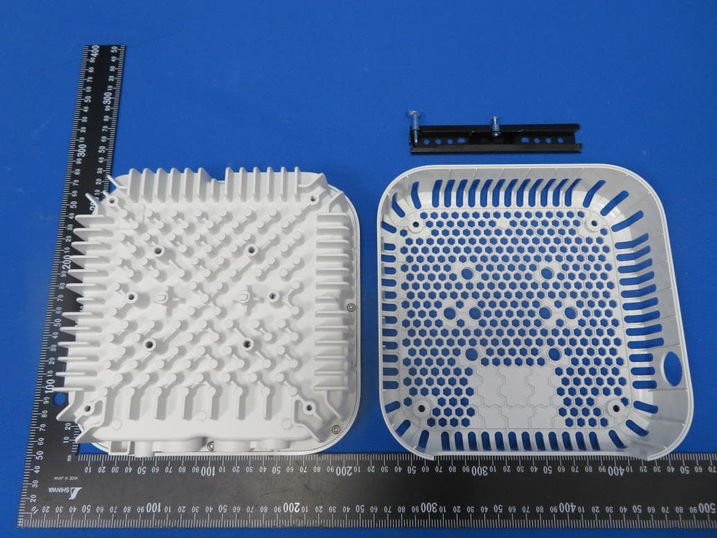
Click to zoom
Application Details
- Equipment Class
- NII - Unlicensed National Information Infrastructure TX
- Date of Grant
- Jun 14, 2020
- Application Purpose
- Original Equipment
- Date of Application
- Jun 07, 2020
- Equipment Note
- ACCESS POINT
- Frequency Range
- 5745.00000000 - 5825.00000000
- Country
- United States
Documents & Files
Document Text
Text extracted from the exhibit documents filed with the FCC. Open a document above to read the original.
Users Manual
Aruba 518 Series Ruggedized Access Point Installation Guide Rev 01 | June 20201 The Aruba 518 Series access points are high-performance, multi-radio wireless devices that can be deployed in either controller-based (ArubaOS) or controllerless (Aruba Instant) network environment. The Aruba 518 Series access points support IEEE 802.11ax standard, delivering high performance with the MU- MIMO (Multi-User Multiple-Input, Multiple-Output) technology, while also supporting 802.11a/b/g/n/ac wireless services. Package Contents 518 Series access point Cable gland x 2 USB Type-C console cable x 1 Grounding lug and M4x6 screw x 1 Tools Required Phillips screwdriver (#2 for M4x6 screw) Flat blade screwdriver (Ethernet cable gland covers) 8mm allen or hex key (USB console cover) The weatherproof caps for Ethernet and Console interfaces are connected to the access point, not loose in the package. Mounting kits for use with the 518 Series access points are sold separately. Contact your Aruba sales representative for details. Inform your supplier if there are any incorrect, missing, or damaged parts. If possible, retain the carton, including the original packing materials. Use these materials to repack and return the unit to the supplier if needed. 2Aruba 518 Series Ruggedized Access Point| Installation Guide Hardware Overview Figure 1 518 Series Front View Figure 2 518 Series Bottom View 5G0 2G0 5G2 5G1 2G1 5G3 E1 Grounding Point USB Console Port & Reset Button E0 System LED Aruba 518 Series Ruggedized Access Point| Installation Guide3 External Antenna Connectors The AP-518 access point is equipped with six external antenna connectors. The connectors are labeled 2G0, 2G1, 5G0, 5G1, 5G2, and 5G3. LED The 518 Series access point is equipped with one LED that indicates the system status of the access point. Ethernet Ports The Aruba 518 Series access points are equipped with two Ethernet ports (E0 and E1): E0 port: 100/1000/2500Base-T auto-sensing MDI/MDX wired RJ45 network connectivity port E1 port: 100/1000Base-T auto-sensing MDI/MDX wired RJ45 network connectivity port ! External antennas for this device must be installed by an Aruba Certified Mobility Professional (ACMP) or other Aruba-certified technician, using manufacturer-approved antennas only. The Equivalent Isotropically Radiated Power (EIRP) levels for all external antenna devices must not exceed the regulatory limit set by the host country/domain. Installers are required to record the antenna gain for this device in the system management software. A list of approved antennas can be found at: http://www.arubanetworks.com/assets/og/OG_AP-518Series.pdf. Les antennes externes pour cet appareil doivent être installées par un professionnel de la mobilité certifié Aruba (ACMP) ou un autre technicien certifié Aruba, en utilisant uniquement des antennes approuvées par le fabricant. Les niveaux équivalents de puissance à rayonnement isotrope (EIRP) pour tous les périphériques d'antenne externe ne doivent pas dépasser la limite réglementaire définie par le pays hôte / domaine. Les installateurs doivent enregistrer le gain d'antenne pour cet appareil dans le logiciel de gestion du système. Une liste d'antennes approuvées peut être trouvée à http://www.arubanetworks.com/assets/og/OG_AP- 518Series.pdf. Table 1 518 Series LED Meanings during Boot Up LEDColor/StateMeaning System LEDOffNo power to AP RedInitial power-up Green - FlashingAP booting, not ready Green - SteadyAP ready and Gigabit Ethernet connected. The LED turns off after 1200 seconds Green - Yellow, 6 seconds period AP ready and 10/100Mbps Ethernet link established. The LED turns off after 1200 seconds Table 2 518 Series LED Meanings during Operation LEDColor/StateMeaning System LEDSolid RedGeneral fault-Immediate attention required One blink off every 3 seconds Radio 0 fault (5 GHz) Two quick blink off 0.5 seconds apart cycled every 3 seconds Radio 1 fault (2.4GHz) 4Aruba 518 Series Ruggedized Access Point| Installation Guide Power Both E0 and E1 ports support PoE-in, allowing the AP to draw power from an 802.3at/802.3bt PoE power source. When the AP is powered by both E0 and E1 ports simultaneously, the AP can be configured by management software to source PoE power from either port, or to combine power from both ports. The 518 Series access points support the Intelligent Power Monitoring (IPM) feature, to report AP power consumption and enable intelligent management of power-save capabilities. Table 3 lists operational restrictions when the AP is powered by different power options. Table 3 Power Options and Operational Restrictions Grounding Point Always remember to protect the access point by installing grounding lines. The ground connection must be complete before connecting power to the access point enclosure. USB Type-C Console Port Use the included USB Type-C console cable to connect the access point to a laptop or a serial terminal for direct management. Reset Button The reset button can be used to reset the access point to factory default settings or turn off/on the LED display. There are two ways to reset the access point to factory default settings: Reset the AP during normal operation Press and hold down the reset button using a small, narrow object such as a paper clip for more than 10 seconds during normal operation. Reset the AP while powering up 1. Press and hold down the reset button using a small, narrow object such as a paper clip while the access point is not powered on via PoE. 2. Connect the power supply (PoE) to the access point while the reset button is being held down. 3. Release the reset button on the access point after 15 seconds. To turn off/on the LED display, press and release the reset button using a small, narrow object, such as a paperclip for less than 10 seconds during normal operation of the access point. Power SourceIPMRestrictions 1 x 802.3bt PoE n/aNo restrictions, all capabilities available. 2 x 802.3at PoE n/aNo restrictions, all capabilities ava…
Text truncated - open the document above for the full version.
Cover Letter(s)
DECLARATION OF CONFORMITY FCC ID: Q9DAPIN0518 Date: May 21, 2020 Please be notified that we, the undersigned, Hewlett Packard Enterprise Company declares that the product which bears the above FCC ID is also compliant with the FCC requirements for sDOC. And the sDoC procedure shall be carried out prior to marketing the device in the US. Sincerely, ---------------------------------------------------------- Name: Phillip Carranco Position: Regulatory Compliance Manager Hewlett Packard Enterprise Company
Cover Letter(s)
Date: 2020-05-21 Federal Communications Commission 7435 Oakland Mills Road Columbia MD 21046 To whom it may concern: I, the undersigned, hereby authorize MRT Technology (Taiwan) Co., Ltd to act on our behalf in all manners relating to application for equipment authorization, including signing of all documents relating to these matters. Any and all acts carried out by MRT Technology (Taiwan) Co., Ltd on our behalf shall have the same effect as acts of our own. I, the undersigned, hereby certify that we are not subject to a denial of federal benefits, that includes FCC benefits, pursuant to Section 5301 of the Anti-Drug Abuse Act of 1988, 21 U.S.C. 853(a). In authorizing MRT Technology (Taiwan) Co., Ltd as our representative, we still recognize that we are responsible to: a) comply with the relevant provisions of the certification program; b) make all necessary arrangements for the conduct of the evaluation, including provision for examining documentation and access to all areas, records (including internal audit reports) and personnel for the purposes of evaluation (e.g. testing, inspection, assessment, surveillance, reassessment) and resolution of complaints; c) make claims regarding certification only in respect of the scope for which certification has been granted; d) do not use our product certification in such a manner as to bring the Certification Division into disrepute and not make any statement regarding our product certification which the Certification Division may consider misleading or unauthorized; e) upon suspension or cancellation of certification, discontinue use of all advertising matter that contains any reference thereto and return any certification documents as required by the Certification Division; f) use certification only to indicate the products are certified as being in conformity with specified standards; g) endeavor to ensure that no certificate or report nor any part thereof is used in a misleading manner; h) ensure that any reference to our product certification in communication media such as documents, brochures or advertising, complies with the requirements of the Certification Division; i) keep a record of all complaints made known to us relating to the product’s compliance with requirements of the relevant standard and to make these records available when requested; j) take appropriate action with respect to such complaints and any deficiencies found in products or services that affect compliance with the requirements for certification; k) document the actions taken. This authorization is valid until further written notice from the applicant. Sincerely Yours, Name: Phillip Carranco Position: Regulatory Compliance Manager Hewlett Packard Enterprise Company
Cover Letter(s)
Federal Communications Commission 7435 Oakland Mills Road Columbia MD 21046 Subject: Request for Confidentiality FCC ID: (Q9DAPIN0518) To Whom It May Concern: Pursuant to the provisions of Sections 0.457 and 0.459 of the Commission’s rules (47 CFR §§ 0.457, 0.459), we are requesting the Commission to withhold the following attachments as confidential document from public disclosure indefinitely. Schematic Diagram Block Diagram Theory of Operation Software Security Requirements Cover Letter Antenna Specification Above mentioned document contains detailed system and equipment description are considered as proprietary information in operation of the equipment. The public disclosure of above documents might be harmful to our company and would give competitor an unfair advantage in the market. In additional to above mentioned documents, pursuant to Public Notice DA 04-1705 of the Commission’s policy, in order to comply with the marketing regulations in 47 CFR §2.803 and the importation rules in 47 CFR §2.1204, while ensuring that business sensitive information remains confidential until the actual marketing of newly authorized devices. We are requesting the commission to grant short-term confidentiality request on the following attachments until (180 days): External Photos Internal Photos Test Setup Photos User Manual It is our understanding that all measurement test reports, FCC ID label format and correspondent during certification review process cannot be granted as confidential documents and those information will be available for public review once the grant of equipment authorization is issued. Best Regards Name: Phillip Carranco Position: Regulatory Compliance Manager Hewlett Packard Enterprise Company 2020-05-21
Cover Letter(s)
Software Defined Radio (SDR) Date: May 21, 2020 Federal Communications Commission Authorization and Evaluation Division 7435 Oakland Mills RoadColumbia, MD 21046 Attention: OET Dept. FCC ID: Q9DAPIN0518 Regarding Certification as a Software Defined Radio This letter is to notify the FCC of our intentions regarding submitting for grant approvals as a Software Defined Radio in accordance to KDB 442812 D01 SDR Apps Guide v02r03. All supporting documentation to be approved as an SDR will be included. Sign by: Print Name: Phillip Carranco Title: Regulatory Compliance Manager Company: Hewlett Packard Enterprise Company
Cover Letter(s)
Professional Installation Attestation Date: May 21, 2020 FCC ID: Q9DAPIN0518 IC: 4675A-APIN0518 TCB: Hewlett Packard Enterprise (Aruba Networks), declare that the above reference product is professionally installed. The APEX0518 is intended for enterprise level installations. HPE supports direct sales to large customers and sales via value-added resellers/distributors. There are no retail or mail order sales channels. In all cases, installation is performed by a trained installer. Aruba provides a certified training program. The complexity of the Aruba OS makes training a requirement for installation and operation. Without training, a user would not be able to perform the initial configuration that would enable transmission of the access points. It is during the initial provisioning of any APs that the There is a specific ordering guide that provides a list of acceptable antennas for a particular access point. This is referenced in the Installation Guide. Sign by: Print Name: Phillip Carranco Title: Regulatory Compliance Manager Company: Hewlett Packard Enterprise Company
External Photos
Report No.: 2003TW0003-UE 1 of 12 EUT Photograph (1) EUT Photo (2) EUT Photo Report No.: 2003TW0003-UE 2 of 12 (3) EUT Photo (4) EUT Photo Report No.: 2003TW0003-UE 3 of 12 (5) EUT Photo (6) EUT Photo Report No.: 2003TW0003-UE 4 of 12 (7) EUT Photo (8) EUT Photo Report No.: 2003TW0003-UE 5 of 12 (9) EUT Photo (10) EUT Photo (AP-ANT-22) Report No.: 2003TW0003-UE 6 of 12 (11) EUT Photo (ANT-2x2-2314) (12) EUT Photo (ANT-4x4-5314) Report No.: 2003TW0003-UE 7 of 12 (13) EUT Photo (ANT-3x3-5712) (14) EUT Photo (AP-ANT-25) Report No.: 2003TW0003-UE 8 of 12 (15) EUT Photo (AP-ANT-28) (16) EUT Photo (AP-ANT-16) Report No.: 2003TW0003-UE 9 of 12 (17) EUT Photo (AP-ANT-20W) (18) EUT Photo (AP-ANT-45) Report No.: 2003TW0003-UE 10 of 12 (19) EUT Photo (AP-ANT-1W) (20) EUT Photo (AP-ANT-19) Report No.: 2003TW0003-UE 11 of 12 (21) EUT Photo (AP-ANT-13B) (22) EUT Photo (AP-ANT-48) Report No.: 2003TW0003-UE 12 of 12 (23) EUT Photo (AP-ANT-40)
ID Label/Location Info
Label and Label Location
Internal Photos
Report No.: 2003TW0003-UE 1 of 15 EUT Photograph (1) EUT Photo (2) EUT Photo Report No.: 2003TW0003-UE 2 of 15 (3) EUT Photo (4) EUT Photo Report No.: 2003TW0003-UE 3 of 15 (5) EUT Photo (6) EUT Photo Report No.: 2003TW0003-UE 4 of 15 (7) EUT Photo (8) EUT Photo Report No.: 2003TW0003-UE 5 of 15 (9) EUT Photo (10) EUT Photo Report No.: 2003TW0003-UE 6 of 15 (11) EUT Photo (12) EUT Photo Report No.: 2003TW0003-UE 7 of 15 (13) EUT Photo (14) EUT Photo Report No.: 2003TW0003-UE 8 of 15 (15) EUT Photo (16) EUT Photo Report No.: 2003TW0003-UE 9 of 15 (17) EUT Photo (18) EUT Photo Report No.: 2003TW0003-UE 10 of 15 (19) EUT Photo (20) EUT Photo Report No.: 2003TW0003-UE 11 of 15 (21) EUT Photo (22) EUT Photo Report No.: 2003TW0003-UE 12 of 15 (23) EUT Photo (24) EUT Photo Report No.: 2003TW0003-UE 13 of 15 (25) EUT Photo (26) EUT Photo Report No.: 2003TW0003-UE 14 of 15 (27) EUT Photo (28) EUT Photo Report No.: 2003TW0003-UE 15 of 15 (29) EUT Photo (30) EUT Photo
RF Exposure Info
MRT Technology (Taiwan) Co., Ltd Report No.: 2003TW0003-U6 Phone: +886-3-3288388 Report Version: V02 Web: www.mrt-cert.com Issue Date: 06-01-2020 Page Number: 1 of 7 RF Exposure Evaluation Declaration FCC ID: Q9DAPIN0518 APPLICANT: Hewlett Packard Enterprise Company Application Type: Certification Product: ACCESS POINT Model No.: APIN0518 Trademark: , FCC Classification: Digital Transmission System (DTS) Unlicensed National Information Infrastructure (UNII) Reviewed By: ( Paddy Chen ) Approved By: ( Chenz Ker ) The test results relate only to the samples tested. The test results shown in the test report are traceable to the national/international standards through the calibration of the equipment and evaluated measurement uncertainty herein. The test report shall not be reproduced except in full without the written approval of MRT Technology (Taiwan) Co., Ltd. Report No.: 2003TW0003-U6 Page Number: 2 of 7 Revision History Report No. Version Description Issue Date Note 2003TW0003-U6 Rev. 01 Initial report 05-23-2020 Invalid 2003TW0003-U6 Rev. 02 Revise some information 06-01-2020 Valid Report No.: 2003TW0003-U6 Page Number: 3 of 7 1. PRODUCT INFORMATION 1.1. Equipment Description Product Name: ACCESS POINT Model No.: APIN0518 Wi-Fi Specification: 802.11a/b/g/n/ac/ax Bluetooth Specification: v5.0 single mode Zigbee Specification: 802.15.4 Operating Temperature: -40 ~ 65 °C Power Type: POE input Operating Environment: Indoor Use Report No.: 2003TW0003-U6 Page Number: 4 of 7 1.2. Antenna Description Antenna No. Polarization Frequency Band (GHz) Model No. Max Peak Gain (dBi) BF Dir Gain (dBi) CDD Dir Gain (dBi) For Power For PSD Wi-Fi External Antenna List (2.4GHz 2*2 MIMO, 5GHz 4*4 MIMO) 1 Omni 2.4 AP-ANT-40 4.0 7.01 4.0 7.01 5 5.0 11.02 5.0 11.02 2 Omni 2.4 AP-ANT-19 3.0 6.01 3.0 6.01 5 6.0 12.02 6.0 12.02 3 Omni 2.4 AP-ANT-1W 3.8 6.81 3.8 6.81 5 5.8 11.82 5.8 11.82 4 Omni 2.4 AP-ANT-13B 2.3 5.31 2.3 5.31 5 4.0 10.02 4.0 10.02 5 Omni 2.4 AP-ANT-20W 2.0 5.01 2.0 5.01 5 2.0 8.02 2.0 8.02 6 Omni 2.4 AP-ANT-22 2.0 5.01 2.0 5.01 5 4.0 10.02 4.0 10.02 7 Omni 2.4 AP-ANT-16 3.9 6.91 3.9 6.91 5 4.7 10.72 4.7 10.72 8 (Note 3) Directional 2.4 AP-ANT-45 4.5 4.5 4.5 4.5 5 5.5 8.51 5.5 8.51 9 (Note 3) Directional 2.4 AP-ANT-48 8.5 8.5 8.5 8.5 5 8.5 11.51 8.5 11.51 10 (Note 3) Directional 2.4 ANT-2x2-2314 14.0 14.0 14.0 14.0 11 (Note 3) Directional 5 ANT-4x4-5314 14.0 17.01 14.0 17.01 12 (Note 3) Directional 5 ANT-3x3-5712 11.5 14.51 11.5 14.51 13 (Note 3) Directional 2.4 AP-ANT-25 5.0 5.0 5.0 5.0 5 5.0 8.01 5.0 8.01 14 (Note 3) Directional 2.4 AP-ANT-28 7.5 7.5 7.5 7.5 5 7.5 10.51 7.5 10.51 Bluetooth / ZigBee Internal Antenna PCB 2.4 4.2 Note 1: The EUT supports Cyclic Delay Diversity (CDD) mode, and CDD signals are correlated. Note 2: The EUT also supports Beam Forming mode, and the Beam Forming support 802.11n/ac/ax, not include 802.11a/b/g. Directional gain = G ANT + BF Gain, BF Gain was declared by the applicant. Note 3: These antennas have Cross-Polarized design, only each two outputs driving a pair of antennas that are cross-polarized, the detail see the antenna specification. Report No.: 2003TW0003-U6 Page Number: 5 of 7 2. RF Exposure Evaluation 2.1. Limits According to FCC 1.1310: The criteria listed in the following table shall be used to evaluate the environment impact of human exposure to radio frequency (RF) radiation as specified in 1.1307(b) LIMITS FOR MAXIMUM PERMISSIBLE EXPOSURE (MPE) Frequency Range (MHz) Electric Field Strength (V/m) Magnetic Field Strength (A/m) Power Density (mW/cm 2 ) Average Time (Minutes) (A) Limits for Occupational/ Control Exposures 300-1500 -- -- f/300 6 1500-100,000 -- -- 5 6 (B) Limits for General Population/ Uncontrolled Exposures 300-1500 -- -- f/1500 6 1500-100,000 -- -- 1 30 f= Frequency in MHz Calculation Formula: Pd = (Pout*G)/(4*pi*r 2 ) Where Pd = power density in mW/cm 2 Pout = output power to antenna in mW G = gain of antenna in linear scale Pi = 3.1416 r = distance between observation point and center of the radiator in cm Pd is the limit of MPE, 1mW/cm². If we know the maximum gain of the antenna and the total power input to the antenna, through the calculation, we will know the distance r where the MPE limit is reached. Report No.: 2003TW0003-U6 Page Number: 6 of 7 2.2. Test Result of RF Exposure Evaluation Product ACCESS POINT Test Item RF Exposure Evaluation Antenna Gain: Refer to clause 1.2. Test Mode Frequency Band (MHz) Max Conducted Power (dBm) Antenna Gain (dBi) Max EIRP (dBm) BLE 2402 ~ 2480 8.50 4.2 12.7 ZigBee 2405 ~ 2480 8.50 4.2 12.7 802.11b/g/n/ax 2412 ~ 2462 27.00 2.0 29.0 802.11a/n/ac/ax 5180 ~ 5320, 5500 ~ 5720, 5745 ~ 5825 30.00 2.0 32.0 Note: Turn-up power from operation description was taken into account for above max conducted power. Test Mode Frequency Band (MHz) Maximum EIRP (dBm) Power Density at R = 20 cm (mW/cm 2 ) Limit (mW/cm 2 ) Bluetooth-LE 2402 ~ 2480 12.7 0.0037 1 ZigBee 2405 ~ 2480 12.7 0.0037 1 802.11b/g/n 2412 ~ 2462 29.0 0.1580 1 802.11a/n/ac/ax 5180 ~ 5320, 5500 ~ 5720, 5745 ~ 5825 32.0 0.3153 1 Note: CONCULISON: Both of the WLAN 2.4GHz Band, WLAN 5GHz Band and BLE Band can transmit simultaneously. The max Power Density at R (20 cm) = 0.0037mW/cm 2 + 0.1580mW/cm 2 + 0.3153mW/cm 2 = 0.4770mW/cm 2 < 1mW/cm 2 . Therefore, the Min Safety Distance is 20cm. The End Report No.: 2003TW0003-U6 Page Number: 7 of 7 Appendix A - EUT Photograph Refer to “2003TW0003-UE” file.
Test Report
MRT Technology (Taiwan) Co., Ltd Report No.: 2003TW0003-U4 Phone: +886-3-3288388 Report Version: V01 Web: www.mrt-cert.com Issue Date: 05-23-2020 Page Number: 1 of 561 FCC ID: Q9DAPIN0518 APPLICANT: Hewlett Packard Enterprise Company Application Type: Certification Product: ACCESS POINT Model No.: APIN0518 Brand Name: , FCC Classification: Unlicensed National Information Infrastructure (NII) FCC Rule Part(s): Part15 Subpart E (Section 15.407) Test Procedure(s): ANSI C63.10-2013, KDB 662911 D01v02r01 Test Date: December 25, 2019 ~ May 18, 2020 MEASUREMENT REPORT FCC PART 15.407 WLAN 802.11a/n/ac/ax Reviewed By: ( Paddy Chen ) Approved By: (Chenz Ker) The test results relate only to the samples tested. This equipment has been shown to be capable of compliance with the applicable technical standards as indicated in the measurement report and was tested in accordance with the measurement procedures specified in ANSI C63.10-2013. Test results reported herein relate only to the item(s) tested. The test report shall not be reproduced except in full without the written approval of MRT Technology (Taiwan) Co., Ltd. Report No.: 2003TW0003-U4 Page Number: 2 of 561 Revision History Report No. Version Description Issue Date Note 2003TW0003-U4 Rev. 01 Initial report 05-23-2020 Valid Report No.: 2003TW0003-U4 Page Number: 3 of 561 CONTENTS Description Page General Information ....................................................................................................................... 6 1. INTRODUCTION ..................................................................................................................... 7 1.1. Scope ........................................................................................................................... 7 1.2. MRT Test Location ....................................................................................................... 7 2. PRODUCT INFORMATION ..................................................................................................... 8 2.1. Equipment Description .................................................................................................. 8 2.2. Product Specification Subjective to this Report ............................................................. 8 2.3. Working Frequencies for this report .............................................................................. 9 2.4. Description of Available Antennas ............................................................................... 10 2.5. Description of Antenna RF Port ................................................................................... 11 2.6. Test Mode .................................................................................................................. 12 2.7. Description of Test Software ....................................................................................... 12 2.8. Duty Cycle .................................................................................................................. 13 2.9. EMI Suppression Device(s)/Modifications ................................................................... 14 2.10. Labeling Requirements ............................................................................................... 15 3. DESCRIPTION OF TEST ...................................................................................................... 16 3.1. Measurement Procedure ............................................................................................ 16 3.2. AC Line Conducted Emissions ................................................................................... 16 3.3. Radiated Emissions .................................................................................................... 17 4. ANTENNA REQUIREMENTS ................................................................................................ 18 5. TEST EQUIPMENT CALIBRATION DATE ............................................................................ 19 6. MEASUREMENT UNCERTAINTY ......................................................................................... 20 7. TEST RESULT ...................................................................................................................... 21 7.1. Summary .................................................................................................................... 21 7.2. 26dB Bandwidth Measurement ................................................................................... 22 7.2.1. Test Limit .................................................................................................................... 22 7.2.2. Test Procedure used ................................................................................................... 22 7.2.3. Test Setting ................................................................................................................. 22 7.2.4. Test Setup .................................................................................................................. 22 7.2.5. Test Result .................................................................................................................. 23 7.3. 6dB Bandwidth Measurement ..................................................................................... 40 7.3.1. Test Limit .................................................................................................................... 40 7.3.2. Test Procedure used ................................................................................................... 40 Report No.: 2003TW0003-U4 Page Number: 4 of 561 7.3.3. Test Setting ................................................................................................................. 40 7.3.4. Test Setup .................................................................................................................. 40 7.3.5. Test Result ................................................................…
Text truncated - open the document above for the full version.
Test Report
Report No.: 2003TW0003-U4 Page Number: 36 of 561 802.11ax-HE40 26dB Bandwidth - Ant 0 / Ant 0 + 1 + 2 + 3 Channel 38 (5190MHz) Channel 46 (5230MHz) Channel 54 (5270MHz) Channel 62 (5310MHz) Channel 102 (5510MHz) Channel 118 (5590MHz) Channel 134 (5670MHz) Channel 142 (5710MHz) Report No.: 2003TW0003-U4 Page Number: 37 of 561 802.11ax-HE40 26dB Bandwidth - Ant 0 / Ant 0 + 1 + 2 + 3 Channel 151 (5755MHz) Channel 159 (5795MHz) Report No.: 2003TW0003-U4 Page Number: 38 of 561 802.11ax-HE80 26dB Bandwidth - Ant 0 / Ant 0 + 1 + 2 + 3 Channel 42 (5210MHz) Channel 58 (5290MHz) Channel 106 (5530MHz) Channel 122 (5610MHz) Channel 138 (5690MHz) Channel 155 (5775MHz) Report No.: 2003TW0003-U4 Page Number: 39 of 561 802.11ax-HE160 26dB Bandwidth - Ant 0 / Ant 0 + 1 + 2 + 3 Channel 50 (5250MHz) Channel 114 (5570MHz) Report No.: 2003TW0003-U4 Page Number: 40 of 561 7.3. 6dB Bandwidth Measurement 7.3.1.Test Limit The minimum 6dBbandwidth shall be at least 500 kHz. 7.3.2.Test Procedure used ANSI C63-2013 - Section 12.4.2 7.3.3.Test Setting 1. Set center frequency to the nominal EUT channel center frequency. 2. RBW = 100 kHz. 3. VBW≧ 3 × RBW. 4. Detector = Peak. 5. Trace mode = max hold. 6. Sweep = auto couple. 7. Allow the trace to stabilize. 8. Measure the maximum width of the emission that is constrained by the frequencies associated with the two outermost amplitude points (upper and lower frequencies) that are attenuated by 6 dB relative to the maximum level measured in the fundamental emission. 7.3.4.Test Setup Report No.: 2003TW0003-U4 Page Number: 41 of 561 7.3.5.Test Result Product ACCESS POINT Temperature 25°C Test Engineer Kevin Ker Relative Humidity 52% Test Site SR2 Test Date 2020/01/15 Test Mode Data Rate/ MCS Channel No. Frequency (MHz) 6dB Bandwidth (MHz) Limit (MHz) Result Ant 0 / Ant 0 + 1 + 2 + 3 802.11a 6Mbps 149 5745 16.37 ≥ 0.5 Pass 802.11a 6Mbps 157 5785 16.33 ≥ 0.5 Pass 802.11a 6Mbps 165 5825 16.37 ≥ 0.5 Pass 802.11ac-VHT20 MCS0 149 5745 17.58 ≥ 0.5 Pass 802.11ac-VHT20 MCS0 157 5785 17.58 ≥ 0.5 Pass 802.11ac-VHT20 MCS0 165 5825 17.58 ≥ 0.5 Pass 802.11ac-VHT40 MCS0 151 5755 36.10 ≥ 0.5 Pass 802.11ac-VHT40 MCS0 159 5795 36.08 ≥ 0.5 Pass 802.11ac-VHT80 MCS0 155 5775 75.26 ≥ 0.5 Pass 802.11ax-HE20 MCS0 149 5745 19.01 ≥ 0.5 Pass 802.11ax-HE20 MCS0 157 5785 18.98 ≥ 0.5 Pass 802.11ax-HE20 MCS0 165 5825 18.97 ≥ 0.5 Pass 802.11ax-HE40 MCS0 151 5755 37.45 ≥ 0.5 Pass 802.11ax-HE40 MCS0 159 5795 36.66 ≥ 0.5 Pass 802.11ax-HE80 MCS0 155 5775 76.09 ≥ 0.5 Pass Report No.: 2003TW0003-U4 Page Number: 42 of 561 802.11a 6dB Bandwidth - Ant 0 / Ant 0 + 1 + 2 + 3 Channel 149 (5745MHz) Channel 157 (5785MHz) Channel 165 (5825MHz) Report No.: 2003TW0003-U4 Page Number: 43 of 561 802.11ac-VHT20 6dB Bandwidth - Ant 0 / Ant 0 + 1 + 2 + 3 Channel 149 (5745MHz) Channel 157 (5785MHz) Channel 165 (5825MHz) 802.11ac-VHT40 6dB Bandwidth - Ant 0 / Ant 0 + 1 + 2 + 3 Channel 151 (5755MHz) Channel 159 (5795MHz) Report No.: 2003TW0003-U4 Page Number: 44 of 561 802.11ac-VHT80 6dB Bandwidth - Ant 0 / Ant 0 + 1 + 2 + 3 Channel 155 (5775MHz) Report No.: 2003TW0003-U4 Page Number: 45 of 561 802.11ax-HE20 6dB Bandwidth - Ant 0 / Ant 0 + 1 + 2 + 3 Channel 149 (5745MHz) Channel 157 (5785MHz) Channel 165 (5825MHz) 802.11ax-HE40 6dB Bandwidth - Ant 0 / Ant 0 + 1 + 2 + 3 Channel 151 (5755MHz) Channel 159 (5795MHz) Report No.: 2003TW0003-U4 Page Number: 46 of 561 802.11ax-HE80 6dB Bandwidth - Ant 0 / Ant 0 + 1 + 2 + 3 Channel 155 (5775MHz) Report No.: 2003TW0003-U4 Page Number: 47 of 561 7.4. Output Power Measurement 7.4.1.Test Limit For an indoor access point operating in the band 5.15-5.25 GHz, the maximum conducted output power over the frequency band of operation shall not exceed 1 W provided the maximum antenna gain does not exceed 6 dBi. For the 5.25-5.35 GHz and 5.47-5.725 GHz bands, the maximum conducted output power over the frequency bands of operation shall not exceed the lesser of 250 mW or 1…
Text truncated - open the document above for the full version.
Contact Information
Applicant
Mark Hill(Principal Engineer)
Technical Contact
MRT Technology (Suzhou) Co., LtdJame Yuan
[email protected]+86-512-6630 8358
D8 Building, No.2 Tianedang Rd., Wuzhong Economic · Suzhou · China
Test Firm
MRT Technology (Taiwan) Co., LtdChenz Ker
Technical Specifications
| # | Rule Parts | Frequency Range | Power Output |
|---|---|---|---|
| 4 | 15E | 5.75 GHz - 5.83 GHz | 625.00 mW |
Other Applications from Hewlett Packard Enterprise Company
Q9DAPINH721
Jul 17, 2026Access Point
Equipment Class
6ID - 15E 6 GHz Low Power Indoor Access PointQ9DASIN0307
Dec 22, 2025HPE Aruba User Experience Sensor
Equipment Class
DTS - Digital Transmission SystemQ9DASIN0308
Nov 23, 2025HPE Aruba User Experience Sensor
Equipment Class
DTS - Digital Transmission SystemQ9DAPEX0764
Nov 20, 2025ACCESS POINT
Equipment Class
DTS - Digital Transmission SystemQ9DAPIN0763
Sep 29, 2025ACCESS POINT
Equipment Class
NII - Unlicensed National Information Infrastructure TX