Q9DAPIN0635Access Point
Hewlett Packard Enterprise Company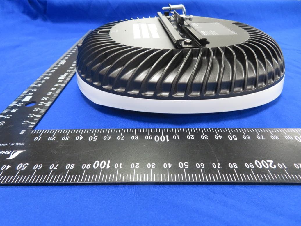
Click to zoom
Application Details
- Equipment Class
- DTS - Digital Transmission System
- Date of Grant
- Jul 28, 2021
- Application Purpose
- Original Equipment
- Date of Application
- Jun 20, 2021
- Equipment Note
- Access Point
- Frequency Range
- 2412.00000000 - 2462.00000000
- Country
- United States
Documents & Files
Document Text
Text extracted from the exhibit documents filed with the FCC. Open a document above to read the original.
Users Manual
Aruba 630 Series Campus Access Points Installation Guide Rev01 | April 20211 The tri-radio Aruba 630 Series access points support the IEEE 802.11ax WLAN standard in the 6GHz band (Wi-Fi 6E) as well as the 5GHz and 2.4GHz bands, delivering high performance and capacity with MIMO (Multiple-Input, Multiple-Output) and OFDMA (Orthogonal Frequency Division Multiple Access) technologies, while also supporting IEEE 802.11a/b/g/n/ac wireless services. Package Contents Aruba 630 Series Campus Access Point (with a pre-installed mount bracket) Hardware Overview The following sections outline the hardware components of the 630 Series access points. Figure 1 AP-635 Front View LEDs The LED displays located on the front panel of the access point indicate the following functions: System Status LED The System Status LED indicates the operating condition of the access point, See Table 1. The AP mount bracket attaches to a variety of mount kits (sold separately). Inform your supplier if there are any incorrect, missing, or damaged parts. If possible, retain the carton, including the original packing materials. Use these materials to repack and return the unit to the supplier if needed. 2Aruba 630 Series Campus Access Points| Installation Guide Table 1 System Status LED 2G/5G/6G Radio Status LEDs The 2G/5G/6G Radio Status LEDs indicate the operating mode of the access point’s 2G/5G/6G radios. See Table 2. Table 2 2G/5G/6G Radio Status LEDs LED Display Settings The LEDs have three operating modes that can be selected in the system management software: Default mode: refer to Table 1and Table 2 Off mode: all LEDs are off Blink mode: all LEDs blink green (synchronized) To force the LEDs into off mode or back to software defined mode, press the reset button for a short duration (less than 10 seconds). Color/StateMeaning OffDevice Powered off Green- solidDevice ready, fully functional, no network restrictions Green- blinking 1 1. Blinking: one second on, one second off, 2 seconds cycle. Device booting, not ready Green- flashing off 2 2. Flashing off: mostly on, fraction of a second off, 2 seconds cycle. Device ready, fully functional, either uplink negotiated in sub-optimal speed (<1Gbps) Green- flashing on 3 3. Flashing on: mostly off, fraction of a second on, 2 seconds cycle. Device in deep-sleep mode Amber- solidDevice ready, restricted power mode (limited PoE power available, or IPM restrictions applied), no network restrictions Amber- flashing offDevice ready, restricted power mode (limited PoE power available, or IPM restrictions applied), uplink negotiated in sub-optimal speed RedSystem error condition - Immediate attention required Color/StateMeaning OffDevice powered off, or radio disabled Green- solidRadio enabled in access mode Green- flashing offRadio enabled in uplink or mesh mode Amber- solidRadio enabled in monitor or spectrum analysis mode ! Pressing the reset button for longer than 10 seconds may cause the AP to reset and return to factory default state. Aruba 630 Series Campus Access Points| Installation Guide3 Figure 2 AP-635 Rear View Bluetooth 5.0 Low Energy and 802.15.4 Radio The 630 Series is equipped with an integrated BLE 5.0 and 802.15.4 radio that provides the following capabilities: location beacon applications wireless console access IOT gateway applications Console Port The console port is a Micro-B connector located on the back of the 630 Series. Use the proprietary AP-CBL-SERU cable or AP-MOD-SERU module (sold separately) for direct local management of the 630 Series when connected to a serial terminal or laptop. For pin-out details, refer to Figure 3. Figure 3 Micro-B Port Pin-out Ethernet Ports The 630 Series is equipped with two 100/1000/2500Base-T auto-sensing MDI/MDX wired RJ45 Ethernet ports (E0 and E1). The 2.5bps speed complies with NBase-T and 802.3bz specifications. Both ports are compliant with 802.3ab 1000Base-T Gigabit Ethernet and 802.3az (Energy Efficient Ethernet) standards. Both ports support 802.3af, 802.3at and 802.3bt Power over Ethernet compliance to accept power from a POE source, such as a PoE midspan injector, or a network switch. Kensington Lock Slot The 630 Series is equipped with a Kensington lock slot for additional physical security. Kensington Lock Slot Console Reset USB 2.0 Interface E0 E1 DC Jack 1: N/C 2: RXD 3: TXD 4: GND 5: GND 4Aruba 630 Series Campus Access Points| Installation Guide USB 2.0 Interface The USB 2.0 interface located on the top of the 630 Series is compatible with selected cellular modems and other peripherals. When active, this interface can supply up to 5W/1A to a connected device. Reset Button The reset button can be used to reset the access point to factory default settings or turn off/on the LED display. Use one of the following methods to reset the access point to factory default settings: To reset during normal operation: 1.Hold the reset button for more than 10 seconds while the access point is running. 2.Release the reset button. To reset during power up, hold the reset button while the access point is powering up. The system status LED will flash again within 15 seconds indicating that the reset is completed. The access point will now continue to boot with the factory default settings. To toggle the LED display between Off and Blinking: During the normal operation of the access point, shortly press and release the reset button for less than 10 seconds using a small, narrow object, such as a paperclip. Power Both E0 and E1 ports support PoE-in (AP is a PoE-PD device), allowing the device to draw power from compliant PoE power sources. If PoE is not available, a proprietary AP-AC2-12B power adapter (sold separately) can be used to power the access point. When both PoE and DC power sources are available, the DC power source takes precedence. In that case, the access point simultaneously draws a minimal current from the PoE source. In the event that the DC source fails, the access point switches to the PoE sources.…
Text truncated - open the document above for the full version.
Users Manual
DATA SHEET For enterprises who need more wireless capacity and wider channels, Aruba 630 Series Campus APs are designed to take advantage of the 6 GHz band via three dedicated radios. By using the 6 GHz band, capacity is more than doubled – so you can meet growing demand due to bandwidth-hungry video, increasing numbers of client and IoT devices and growth in cloud. Unique to Aruba, the 630 Series includes ultra tri-band filtering and dual 2.5 Gbps ethernet ports to eliminate coverage gaps, provide greater resiliency, and deliver fast, secure connectivity. MORE CAPACITY AND WIDER CHANNELS The 630 Series APs are designed to take advantage of the 6 GHz band, which translates into far greater speeds, wider channels for multi-gigabit traffic, and less interference. It delivers 3.9 Gbps maximum aggregate data rates Tri-radio, 2x2:2 MIMO in all three bands (3.9 Gbps aggregate peak). ARUBA 630 SERIES CAMPUS ACCESS POINTS Fast, resilient, and secure Wi-Fi 6E connectivity KEY FEATURES • Unlocks the 6 GHz band to more than double the available capacity • Comprehensive tri-band coverage across 2.4 GHz, 5 GHz, and 6 GHz to deliver 3.9 Gbps maximum aggregate data rate • Up to seven 160 MHz channels in 6 GHz support low-latency, bandwidth-hungry applications like high-definition video and augmented reality/virtual reality applications • Unique ultra-triband filtering enables 5 GHz and 6 GHz to operate without restrictions or interference • High availability with 2.5 Gbps dual ethernets port for hitless failover of ethernet and power BandChannel SizeMaximum throughput 6 GHz160 MHz2.4 Gbps 5 GHz80 MHz1.2 Gbps 2.4 GHz20 MHz287 Mbps Total3.9 Gbps Advantages of 6GHz Wi-Fi 6E provides up to 1200 MHz in the 6 GHz band for higher throughput and improved application performance. With up to seven 160 MHz channels, Wi-Fi 6E can better support low-latency, bandwidth hungry applications like high-definition video and artificial reality/virtual reality applications. Only Wi-Fi 6E capable devices can use the 6 GHz band so there is no interference or slowdowns due to legacy devices. Device class support The 630 Series APs are part of the low power indoor (LPI) device class. This fixed indoor-only class uses lower power levels and does not require an Automated Frequency Coordination service (AFC) to manage incumbent outdoor services which is required for standard class APs. DATA SHEET ARUBA 630 SERIES CAMPUS ACCESS POINTS 2 LESS INTERFERENCE 630 Series Access Points include Aruba’s ultra tri-band filtering, which enables enterprises to take advantage of the high end of 5 GHz with the lower end of 6 GHz without experiencing interference. Since there is only 50 MHz between 5 GHz and the 6 GHz, without advanced filtering, enterprises would likely experience problems between the bands and would therefore be limited in the number of channels available. By applying advanced filtering capabilities, enterprises can take full use of available spectrum without creating coverage gaps or islands. BUSINESS CONTINUITY The Series 630 APs provide high availability with two HPE Smart Rate ethernet ports for hitless failover for both data and power. Configurable to 1 or 2.5 Gbps, these dual ports provide business continuity for mission critical applications. GLOBAL READINESS While the need for more Wi-Fi capacity is recognized across the globe, countries are approaching 6 GHz differently. The 630 Series APs are set up to automatically update regulatory rules once 6E regulations have been approved and certified. EXTEND THE BENEFITS OF WI-FI 6 The 630 Series APs are based on the 802.11ax standard, which means that all its efficiency and security enhancements are also available on the 6 GHz band. Features include Orthogonal frequency-division multiple access (OFDMA), bi-directional multi-user MIMO as well as other capabilities built into Aruba’s Wi-Fi 6 access points. Advantages of OFDMA This capability allows Aruba’s APs to handle multiple 802.11ax capable clients on each channel simultaneously, regardless of device or traffic type. Channel utilization is optimized by handling each transaction via smaller sub-carriers or resource units (RUs), which means that clients are sharing a channel and not competing for airtime and bandwidth. WI-FI OPTIMIZATION Client optimization Aruba’s patented AI-powered ClientMatch technology eliminates sticky client issues by steering a client to the AP where it receives the best radio signal. Client Match steers traffic from the noisy 2.4 GHz band to the preferred 5 GHz or 6 GHz band depending on client capabilities. ClientMatch also dynamically steers traffic to load balance APs to improve the user experience. Automated Wi-Fi radio frequency management To optimize the user experience and provide greater stability, Aruba AirMatch allows organization to automate network optimization using machine learning. AirMatch provides dynamic bandwidth adjustments to support changing device density, enhanced roaming using an even distribution of Effective Isotropic Radiated Power (EIRP) to radios, and real-time channel assignments to mitigate co-channel interference. Application Assurance With Air Slice, organizations can provide application assurance to their users that goes beyond the traditional capabilities of airtime fairness. After the SLAs are configured, Air Slice monitors network usage, automatically allocates radio resources, and dynamically adjusts radio resources as new users connect and applications sessions begin or end. Aruba Advanced Cellular Coexistence (ACC) Unique to Aruba, Advanced Cellular Coexistence uses built-in filtering to automatically minimize the impact of interference from cellular networks, distributed antenna systems (DAS), and commercial small cell or femtocell equipment. Intelligent Power Monitoring (IPM) For better insights into energy consumption, Aruba APs continuously monitor and report hardware energy usage. Unlike other vendor’s access points, Aruba APs can also be configured to …
Text truncated - open the document above for the full version.
Cover Letter(s)
DECLARATION OF CONFORMITY FCC ID: Q9DAPIN0635 Date: May 25, 2021 Please be notified that we, the undersigned, Hewlett Packard Enterprise Company declares that the product which bears the above FCC ID is also compliant with the FCC requirements for sDOC. And the sDoC procedure shall be carried out prior to marketing the device in the US. Sincerely, ---------------------------------------------------------- Name: Phillip Carranco Position: Regulatory Compliance Manager Hewlett Packard Enterprise Company
Cover Letter(s)
Date: 2021-05-25 Federal Communications Commission 7435 Oakland Mills Road Columbia MD 21046 To whom it may concern: I, the undersigned, hereby authorize MRT Technology (Taiwan) Co., Ltd to act on our behalf in all manners relating to application for equipment authorization, including signing of all documents relating to these matters. Any and all acts carried out by MRT Technology (Taiwan) Co., Ltd on our behalf shall have the same effect as acts of our own. I, the undersigned, hereby certify that we are not subject to a denial of federal benefits, that includes FCC benefits, pursuant to Section 5301 of the Anti-Drug Abuse Act of 1988, 21 U.S.C. 853(a). In authorizing MRT Technology (Taiwan) Co., Ltd as our representative, we still recognize that we are responsible to: a) comply with the relevant provisions of the certification program; b) make all necessary arrangements for the conduct of the evaluation, including provision for examining documentation and access to all areas, records (including internal audit reports) and personnel for the purposes of evaluation (e.g. testing, inspection, assessment, surveillance, reassessment) and resolution of complaints; c) make claims regarding certification only in respect of the scope for which certification has been granted; d) do not use our product certification in such a manner as to bring the Certification Division into disrepute and not make any statement regarding our product certification which the Certification Division may consider misleading or unauthorized; e) upon suspension or cancellation of certification, discontinue use of all advertising matter that contains any reference thereto and return any certification documents as required by the Certification Division; f) use certification only to indicate the products are certified as being in conformity with specified standards; g) endeavor to ensure that no certificate or report nor any part thereof is used in a misleading manner; h) ensure that any reference to our product certification in communication media such as documents, brochures or advertising, complies with the requirements of the Certification Division; i) keep a record of all complaints made known to us relating to the product’s compliance with requirements of the relevant standard and to make these records available when requested; j) take appropriate action with respect to such complaints and any deficiencies found in products or services that affect compliance with the requirements for certification; k) document the actions taken. This authorization is valid until further written notice from the applicant. Sincerely Yours, ———————————————— Name: Phillip Carranco Position: Regulatory Compliance Manager Hewlett Packard Enterprise Company
Cover Letter(s)
Federal Communications Commission 7435 Oakland Mills Road Columbia MD 21046 Subject: Request for Confidentiality FCC ID: Q9DAPIN0635 To Whom It May Concern: Pursuant to the provisions of Sections 0.457 and 0.459 of the Commission’s rules (47 CFR §§ 0.457, 0.459), we are requesting the Commission to withhold the following attachments as confidential document from public disclosure indefinitely. Schematic Diagram Block Diagram Theory of Operation Software Security Requirements Cover Letter Above mentioned document contains detailed system and equipment description are considered as proprietary information in operation of the equipment. The public disclosure of above documents might be harmful to our company and would give competitor an unfair advantage in the market. In additional to above mentioned documents, pursuant to Public Notice DA 04-1705 of the Commission’s policy, in order to comply with the marketing regulations in 47 CFR §2.803 and the importation rules in 47 CFR §2.1204, while ensuring that business sensitive information remains confidential until the actual marketing of newly authorized devices. We are requesting the commission to grant short-term confidentiality request on the following attachments until (180 days): External Photos Internal Photos Test Setup Photos User Manual It is our understanding that all measurement test reports, FCC ID label format and correspondent during certification review process cannot be granted as confidential documents and those information will be available for public review once the grant of equipment authorization is issued. Best Regards Name: Phillip Carranco Position: Regulatory Compliance Manager Hewlett Packard Enterprise Company 2021-05-25
Cover Letter(s)
Software Defined Radio (SDR) Date: May 25, 2021 Federal Communications Commission Authorization and Evaluation Division 7435 Oakland Mills Road Columbia, MD 21046 Attention: OET Dept. FCC ID: Q9DAPIN0635 Regarding Certification as a Software Defined Radio This letter is to notify the FCC of our intentions regarding submitting for grant approvals as a Software Defined Radio in accordance to KDB 442812 D01 SDR Apps Guide v02r03. All supporting documentation to be approved as an SDR will be included. Sign by: —————————————————— Print Name: Phillip Carranco Title: Regulatory Compliance Manager Company: Hewlett Packard Enterprise Company
Cover Letter(s)
ZigBee Duty Cycle Attestation Federal Communications Commission 7435 Oakland Mills Road Columbia MD 21046 FCC ID: Q9DAPIN0635 To Whom It May Concern: TCB: Hewlett Packard Enterprise (Aruba Networks), declare that the ZigBee operation, when implemented, will be limited to a duty cycle of 10% or less in any 100ms period. This will not be user configurable. Best Regards Name: Phillip Carranco Position: Regulatory Compliance Manager Hewlett Packard Enterprise Company 2021-05-25
External Photos
1 of 3 EUT Photograph (1) EUT Photo (2) EUT Photo 2 of 3 (3) EUT Photo (4) EUT Photo 3 of 3 (5) EUT Photo (6) EUT Photo
ID Label/Location Info
White PET AP-635Label/Aruba 1 1 1 Text and graphic color:PANTONE COOL GRAY 3C Background color:BLACK Notes: 4. 压花 4012903 4012903-01 FCC ID: Q9DAPIN0635 IC: 4675A-APIN0635 /Product Name: Aruba 635 Aruba 635 Access Point /Model: APIN0635 CAN ICES-3 (B)/NMB-3(B) HPE, Postfach 0001,1122 Wien, Austria 201-210216 Indoor use only T 21 0063 201 R-C-HPe-APIN0635
Internal Photos
1 of 7 EUT Photograph (1) EUT Photo (2) EUT Photo 2 of 7 (3) EUT Photo (4) EUT Photo 3 of 7 (5) EUT Photo (6) EUT Photo 4 of 7 (7) EUT Photo (8) EUT Photo 5 of 7 (9) EUT Photo (10) EUT Photo 6 of 7 (11) EUT Photo (12) EUT Photo 7 of 7 (13) EUT Photo
RF Exposure Info
MRT Technology (Taiwan) Co., Ltd Report No.: 2101TW0003-U6 Phone: +886-3-3288388 Report Version: V1.0 Web: www.mrt-cert.com Issue Date: 05-25-2021 FCC ID: Q9DAPIN0635 Page Number: 1 of 9 RF Exposure Evaluation Declaration FCC ID: Q9DAPIN0635 APPLICANT: Hewlett Packard Enterprise Company Application Type: Certification Product: ACCESS POINT Model No.: APIN0635 Trademark: , FCC Classification: Digital Transmission System (DTS) Unlicensed National Information Infrastructure (NII) 15E 6GHz Low Power Indoor Access Point (6ID) Reviewed By: ( Paddy Chen ) Approved By: (Chenz Ker) The test results relate only to the samples tested. The test results shown in the test report are traceable to the national/international standards through the calibration of the equipment and evaluated measurement uncertainty herein. The test report shall not be reproduced except in full without the written approval of MRT Technology (Taiwan) Co., Ltd. Report No.: 2101TW0003-U6 FCC ID: Q9DAPIN0635 Page Number: 2 of 9 Revision History Report No. Version Description Issue Date Note 2101TW0003-U6 V1.0 Initial report 05-25-2021 Valid Report No.: 2101TW0003-U6 FCC ID: Q9DAPIN0635 Page Number: 3 of 9 CONTENTS Description Page 1. INTRODUCTION ................................................................................................................... 5 1.1. Scope .................................................................................................................................... 5 1.2. MRT Test Location .............................................................................................................. 5 2. PRODUCT INFORMATION ................................................................................................... 6 2.1. Equipment Description........................................................................................................ 6 2.2. Description of Available Antennas..................................................................................... 6 3. RF Exposure Evaluation ..................................................................................................... 7 3.1. Limits ..................................................................................................................................... 7 3.2. Test Result ............................................................................................................................ 8 Appendix - EUT Photograph ...................................................................................................... 9 Report No.: 2101TW0003-U6 FCC ID: Q9DAPIN0635 Page Number: 4 of 9 General Information Applicant Hewlett Packard Enterprise Company Applicant Address 3333 Scott Blvd, Santa Clara, CA 95054, USA Manufacturer Hewlett Packard Enterprise Company Manufacturer Address 3333 Scott Blvd, Santa Clara, CA 95054, USA Test Site MRT Technology (Taiwan) Co., Ltd Test Site Address No. 38, Fuxing Second Rd., Guishan Dist., Taoyuan City 333, Taiwan (R.O.C) MRT FCC Registration No. 291082 Test Facility / Accreditations 1. MRT facility is a FCC registered (Reg. No. 291082) test facility with the site description report on file and is designated by the FCC as an Accredited Test Firm. 2. MRT facility is an IC registered (MRT Reg. No. 21723) test laboratory with the site description on file at Industry Canada. 3. MRT Lab is accredited to ISO 17025 by the Taiwan Accreditation Foundation (TAF Cert. No. 3261) in EMC, Telecommunications and Radio testing for FCC (Designation Number: TW3261), Industry Taiwan, EU and TELEC Rules. Report No.: 2101TW0003-U6 FCC ID: Q9DAPIN0635 Page Number: 5 of 9 1. INTRODUCTION 1.1. Scope Measurement and determination of electromagnetic emissions (EMC) of radio frequency devices including intentional and/or unintentional radiators for compliance with the technical rules and regulations of the Federal Communications Commission and the Innovation, Science and Economic Development Canada and Certification and Engineering Bureau. 1.2. MRT Test Location The map below shows the location of the MRT LABORATORY, its proximity to the Taoyuan City. These measurement tests were conducted at the MRT Technology (Taiwan) Co., Ltd. Facility located at No.38, Fuxing 2nd Rd., Guishan Dist., Taoyuan City 33377, Taiwan (R.O.C). Report No.: 2101TW0003-U6 FCC ID: Q9DAPIN0635 Page Number: 6 of 9 2. PRODUCT INFORMATION 2.1. Equipment Description 2.2. Description of Available Antennas Antenna Type Frequency Band (GHz) Max Peak Gain (dBi) CDD Directional Gain (dBi) BF Directional Gain (dBi) For Power For PSD Wi-Fi Internal Antenna (2*2 MIMO) PIFA 2.4 ~ 2.5 2.90 2.90 5.91 5.91 5.15 ~ 5.9 4.90 4.90 7.91 7.91 5.9 ~ 7.2 4.30 4.30 4.30 4.30 Bluetooth / ZigBee Internal Antenna PIFA 2.4 ~ 2.5 3.0 Note: 1. The EUT supports Cyclic Delay Diversity (CDD) mode, and CDD signals are correlated. For CDD transmissions, directional gain is calculated as follows, N ANT = 2, N SS = 1. If all antennas have the same gain, G ANT , Directional gain = G ANT + Array Gain, where Array Gain is as follows. • For power spectral density (PSD) measurements on all devices, Array Gain = 10 log (N ANT / N SS ) dB = 3.01; • For power measurements on IEEE 802.11 devices, Array Gain = 0 dB for N ANT ≤ 4; 2. The EUT also supports Beam Forming mode, and the Beam Forming support 802.11n/ac/ax, not include 802.11a/b/g. Directional gain = G ANT + BF Gain. BF mode power setting will be less than or equal to CDD power setting. 3. Wi-Fi 6E band antennas are cross polarized, the detail refer to antenna specification. 4. All antenna information is provided by the manufacturer, test laboratory will not be responsible if any error. Product Name ACCESS POINT Model No. APIN0635 Software Version 20210105 spf.11.3.cs Wi-Fi Specification 802.11a/b/g/n/ac/ax Bluetooth Specification v5.0 single mode, BLE only Zigbee Specification 802.15.4 Operating Temperature 0 ~ 50 °C Power Type AC Adapter or PoE input Operating Environment Indoor Use Report No.: 2101…
Text truncated - open the document above for the full version.
Test Report
MRT Technology (Taiwan) Co., Ltd Report No.: 2101TW0003-U1 Phone: +886-3-3288388 Report Version: V1.0 Web: www.mrt-cert.com Issue Date: 05-09-2021 FCC ID: Q9DAPIN0635 Page Number: 1 of 92 FCC ID: Q9DAPIN0635 Applicant: Hewlett Packard Enterprise Company Application Type: Certification Product: ACCESS POINT Model No.: APIN0635 Trademark: , FCC Classification: Digital Transmission System (DTS) FCC Rule Part(s): Part15 Subpart C (Section 15.247) Test Procedure(s): ANSI C63.10-2013 Test Date: January 22 ~ May 08, 2021 MEASUREMENT REPORT FCC PART 15.247 / Bluetooth-LE Reviewed By: ( Paddy Chen ) Approved By: ( Chenz Ker ) The test results relate only to the samples tested. This equipment has been shown to be capable of compliance with the applicable technical standards as indicated in the measurement report and was tested in accordance with the measurement procedures specified in ANSI C63.10-2013. Test results reported herein relate only to the item(s) tested. The test report shall not be reproduced except in full without the written approval of MRT Technology (Taiwan) Co., Ltd. Report No.: 2101TW0003-U1 FCC ID: Q9DAPIN0635 Page Number: 2 of 92 Revision History Report No. Version Description Issue Date Note 2101TW0003-U1 V1.0 Initial report 05-09-2021 Valid Report No.: 2101TW0003-U1 FCC ID: Q9DAPIN0635 Page Number: 3 of 92 CONTENTS Description Page 1. INTRODUCTION ..................................................................................................................... 6 1.1. Scope ........................................................................................................................... 6 1.2. MRT Test Location ....................................................................................................... 6 2. PRODUCT INFORMATION ..................................................................................................... 7 2.1. Equipment Description .................................................................................................. 7 2.2. Product Specification Subjective to this Report ............................................................. 7 2.3. Working Frequencies for this Report ............................................................................. 8 2.4. Description of EUT Filter ............................................................................................... 9 2.5. Description of Available Antennas ............................................................................... 10 2.6. Description of Antenna RF Port ................................................................................... 11 2.7. Duty Cycle ................................................................................................................... 11 2.8. Description of Test Configuration and Software .......................................................... 12 2.9. EMI Suppression Device(s)/Modifications ................................................................... 12 2.10. Labeling Requirements ............................................................................................... 12 3. DESCRIPTION OF TEST ...................................................................................................... 13 3.1. Measurement Procedure ............................................................................................ 13 3.2. AC Line Conducted Emissions ................................................................................... 13 3.3. Radiated Emissions .................................................................................................... 14 4. ANTENNA REQUIREMENTS ................................................................................................ 15 5. TEST EQUIPMENT CALIBRATION DATE ............................................................................ 16 6. MEASUREMENT UNCERTAINTY ......................................................................................... 17 7. TEST RESULT ...................................................................................................................... 18 7.1. Summary .................................................................................................................... 18 7.2. 6dB Bandwidth Measurement ..................................................................................... 19 7.2.1. Test Limit ................................................................................................................ 19 7.2.2. Test Procedure used ............................................................................................... 19 7.2.3. Test Setting ............................................................................................................. 19 7.2.4. Test Setup ............................................................................................................... 19 7.2.5. Test Result .............................................................................................................. 20 7.3. Output Power Measurement ....................................................................................... 22 7.3.1. Test Limit .....…
Text truncated - open the document above for the full version.
Contact Information
Applicant
Mark Hill(Principal Engineer)
Technical Contact
MRT Technology (Suzhou) Co., LtdJame Yuan
[email protected]+86-512-6630 8358
D8 Building, No.2 Tian'edang Rd., Wuzhong Economic · Suzhou · China
Test Firm
MRT Technology (Suzhou) Co., Ltd.Mr. Marlin Chen
[email protected]+86-512-66308358
Technical Specifications
| # | Rule Parts | Frequency Range | Power Output |
|---|---|---|---|
| 3 | 15C | 2.41 GHz - 2.46 GHz | 156.00 mW |
Other Applications from Hewlett Packard Enterprise Company
Q9DAPINH721
Jul 17, 2026Access Point
Equipment Class
6ID - 15E 6 GHz Low Power Indoor Access PointQ9DASIN0307
Dec 22, 2025HPE Aruba User Experience Sensor
Equipment Class
DTS - Digital Transmission SystemQ9DASIN0308
Nov 23, 2025HPE Aruba User Experience Sensor
Equipment Class
DTS - Digital Transmission SystemQ9DAPEX0764
Nov 20, 2025ACCESS POINT
Equipment Class
DTS - Digital Transmission SystemQ9DAPIN0763
Sep 29, 2025ACCESS POINT
Equipment Class
NII - Unlicensed National Information Infrastructure TX