Q9DAPINH103Wireless Access Point
Hewlett Packard Enterprise Company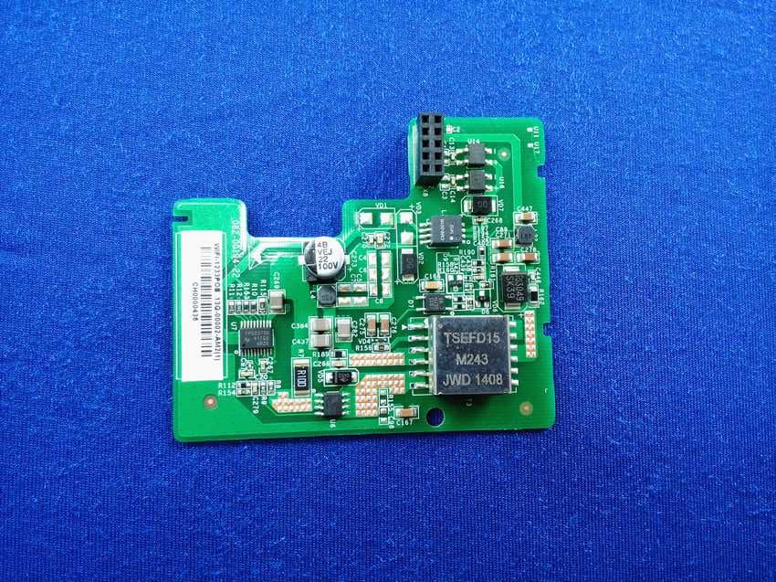
Click to zoom
Application Details
- Equipment Class
- NII - Unlicensed National Information Infrastructure TX
- Date of Grant
- Jul 13, 2014
- Application Purpose
- Original Equipment
- Date of Application
- Jul 05, 2014
- Equipment Note
- Wireless Access Point
- Frequency Range
- 5180.00000000 - 5240.00000000
- Country
- United States
Documents & Files
Document Text
Text extracted from the exhibit documents filed with the FCC. Open a document above to read the original.
Users Manual
Aruba AP-103H Wireless Access Point The Aruba AP-103H wireless access point that supports the IEEE 802.11n standard for high-performance WLAN. This access point uses MIMO (Multiple- Input, Multiple-Output) technology and other high-throughput mode techniques to deliver high-performance, 802.11n 2.4 GHz or 5 GHz functionality while simultaneously supporting existing 802.11a/b/g wireless services. The AP-103H access point works only in conjunction with an Aruba Controller. The Aruba AP-103H access point provides the following capabilities: Wireless transceiver Protocol-independent networking functionality IEEE 802.11a/b/g/n operation as a wireless access point IEEE 802.11a/b/g/n operation as a wireless air monitor Compatibility with IEEE 802.3af PoE Central management configuration and upgrades through an Aruba Controller Package Contents AP-103H Access Point Single Gang Wall-box Mounting bracket 2x Mount Screws Installation Guide (this document) Hardware Overview Figure 1 Front LED The AP-103H is equipped with one LED that indicates the system status of the AP. Figure 2 Rear Console Port The serial console port allows you to connect the AP to a serial terminal or a laptop for direct local management. This port is a 4-pin connector covered by a dust cover. An optional serial adapter cable (AP-CBL-SER) is available for use with the IAP-103 and is sold separately. Figure 3 Bottom Ethernet Ports AP-103H is equipped with a total of three active Ethernet ports (ENET 0-2). ENET 0 is a 10/100/1000Base-T (RJ-45) auto-sensing, MDI/MDX wired-network uplink connectivity port. This port supports IEEE 802.3af Power over Ethernet (PoE), accepting 48VDC as a standard defined Powered Device (PD) from a Power Sourcing Equipment (PSE) such as a PoE midspan injector or network infrastructure that supports PoE. ENET 1 and 2 are 10/100Base-T (RJ-45) auto- sensing, MDI/MDX wired-network downlink connectivity ports, used to provide secure network connectivity to wired devices. ENET 0 is located on the rear of the AP, while ENET 1 and 2 are located on the bottom (Figure 3). Additionally, AP-103H supports a passive pass-through RJ-45 interface to extend a physical connection (typically another Ethernet connection) from the back of the device to a connector on the bottom. Figure 4 Gigabit Ethernet Port Pin-Out Figure 5 Fast Ethernet Port Pin-Out DC Power Socket The AP-103H has a single 12V DC power jack socket to support powering through an AC-to-DC power adapter. Push Button The push button can be used to reset the AP to factory default settings or turn off/on the System Status LED. To reset the AP to factory default settings: 1. Power off the AP. 2. Press and hold the push button using a small, narrow object, such as a paperclip. 3. Power-on the AP without releasing the push button. The system status LED will flash within 5 seconds. 4. Release the push button. The system status LED will flash again within 15 seconds indicating that the reset is completed. The AP will now continue to boot with the factory default settings. To turn off/on the system status LED: During the normal operation of the AP, press the push button using a small, narrow object, such as a paperclip. The system status LED will be turned off/ on immediately. Before You Begin Pre-Installation Network Requirements After WLAN planning is complete and the appropriate products and their placement have been determined, the Aruba controller(s) must be installed and initial setup performed before the Aruba APs are deployed. AP Pre-Installation Checklist Before installing your AP-103H access point, be sure that you have the following: Pre-installed wall box Cat5 UTP cable with network access installed in the wall box One of the following power sources: IEEE 802.3af-compliant Power over Ethernet (PoE) source Aruba AP AC-DC adapter kit (sold separately) Aruba Controller provisioned on the network: Layer 2/3 network connectivity to your access point One of the following network services: Aruba Discovery Protocol (ADP) DNS server with an “A” record DHCP Server with vendor-specific options Summary of the Setup Process Successful setup of an AP-103H access point consists of five tasks, which must be performed in this order: 1. Verify pre-installation connectivity. 2. Identify the specific installation location for each AP. 3. Install each AP. 4. Verify post-installation connectivity. 5. Configure each AP. Verifying Pre-Installation Connectivity Before you install APs in a network environment, make sure that the APs are able to locate and connect to the controller after power on. Specifically, you must verify the following conditions: When connected to the network, each AP is assigned a valid IP address APs are able to locate the controller Refer to the ArubaOS Quick Start Guide for instructions on locating and connecting to the controller. Identifying Specific Installation Locations You can mount the AP-93H access point on a wall or on the ceiling. Use the AP placement map generated by Aruba’s RF Plan software application to determine the proper installation location(s). Each location should be as close as possible to the center of the intended coverage area and should be free from obstructions or obvious sources of interference. These RF absorbers/reflectors/interference sources will impact RF propagation and should have been accounted for during the planning phase and adjusted for in RF plan. Identifying Known RF Absorbers/Reflectors/Interference Sources Identifying known RF absorbers, reflectors, and interference sources while in the field during the installation phase is critical. Make sure that these sources are taken into consideration when you attach an AP to its fixed location. RF absorbers include: Cement/concrete—Old concrete has high levels of water dissipation, which dries out the concrete, allowing for potential RF propagation. New concrete has high levels of water concentration in the concrete, blocking RF signals. Natur…
Text truncated - open the document above for the full version.
Users Manual
486 | AccessPoints(APs)ArubaOS 6.4 | User Guide Configuring an AP using the Provisioning Wizard The easiest way to provision any AP is to use the AP Wizard in the controller WebUI. This wizard will walk you through the specific steps required to provision a campus, remote or Mesh AP. The Wizard includes a help tab that further describes each of the configuration tasks for that deployment type. To access the AP wizard to provision a AP: 1. Select Configuration>Wizards>AP Wizard. TheSpecify Deployment Scenariowindow appears. 2. Select the deployment for the new AP, then clickNextto continue to the next window in the Wizard. 3. Continue working your way through the Wizard to complete the provisioning process. Configuring a AP using the WebUI The following basic steps configure a campus AP on a LAN. Remote APs and mesh APs require additional configuration steps not required for campus APs. For more information, see ConfiguringaRemoteAPand 1. Navigate to theConfiguration > Wireless > AP Installation > Provisioningwindow. 2. Click the checkbox by the AP you want to provision, then clickProvision. The Provisioning window opens. 3. In theAP Parameterssection, click theAP Groupdrop-down list and select the AP group to which this AP should be assigned. The AP group must have at least one virtual AP. 4. (Optional) Some AP models support an external antenna in addition to their internal antenna. If the AP you are provisioning supports an external antenna, the Provisioning window displays an additionalAntenna Parameters section. If you want to use an External antenna for the remote AP you are provisioning, selectExternal Antenna and define settings for that antenna. Otherwise, the remote AP will use its internal antenna by default. 5. If your AP will use Point-to-Point Protocol over Ethernet (PPPoE) to authenticate itself to a service provider, select thePPPoE Parameterscheckbox and enter the following PPPoE values: lPPPoE User Name: Set the PPPoE User Name for this remote AP. lPPPoE Password: Enter and then confirm the PPPoE password for this remote AP. lPPPoE Service Name: Either an ISP name or a class of service configured on the PPPoE server. 6. (Optional) To allow the remote AP to use PEAP to authenticate to 802.1X networks, enter a user name and password in the 802.1X Parameter using PEAP section. 7. In theMaster Discoverysection, define how the AP should identify its WLAN controller. For more information on the different controller discovery methods, seeEnable ControllerDiscovery. 8. (Optional) Define the uplink VLAN. If you configure an uplink VLAN on an AP connected to a port in trunk mode, the AP sends and receives frames tagged with this VLAN on its Ethernet uplink. To define the uplink VLAN, entering a VLAN ID from 1-4095 (inclusive) in theIP Settingssection of theProvisioningwindow, 9. Define how the AP should obtain its IP address. If you have configured an DHCP server to allow APs to get addresses using DHCP, selectObtain IP address using DHCP. For more information on configuring a DHCP server, seeEnableDHCPtoProvideAPswithIPAddresses. Otherwise, selectUse the Following IP address and enter the appropriate values in the following fields: lIP address: IP address for the AP, in dotted-decimal format lSubnet mask: Subnet mask for the IP, in dotted-decimal format. lGateway IP address: The IP address the AP uses to reach other networks. lDNSIPaddress:TheIPaddressoftheDomainNameServer. lDomainname:(optional)Thedefaultdomainname. 10.(Optional)Accesspointscanbeconfiguredinsingle-chainmode,allowingtheradiosofthoseAPstotransmitand receivedatausingonlylegacyratesandsingle-streamHTandVHTratesonasingleradiochainandsingle antennaorantennainterface.OnAPswithexternalantennas,thisfeatureusestheexternalantennainterface labeledA0orANT0(radiochain0);theother(oneortwo)antennainterfacesareleftunused.Ifyouare provisioningan802.11n-capableAP,selecttheEnableforRadio-0orEnableforRadio-1checkboxesinthe Single-ChainModesectiontoenablesingle-chainmodefortheselectedradio.APradiosinsingle-chainmode willtransmitandreceivedatausingonlylegacyratesandsingle-streamHTratesuptoMCS7.Thisfeatureis disabledbydefault. 11.(Optional)DefinetheAPnameorSNMPlocation.TheAPlistsectiondisplayscurrentinformationforanAP,and allowsyoutodefineadditionalparametersforyourAP,suchasAPName,SNMPSystemLocation. 12.ClickApplyandReboot.(ReprovisioningtheAPcausesittoautomaticallyreboot). ConfiguringaRemoteAP AremoteAP(RAP)isrecommendedwhenthenetworkbetweentheAPandcontrollerisanun-trusted/non-routable network,suchastheInternet.Furthermore,aRAPsupportsaninternalDHCPserver,whileacampusAPdoesnot. RemoteAuthentication ThetwomostcommonwaystoprovisionanAPforremoteauthenticationarecertificate-basedAPprovisioningand provisioningusingapre-sharedkey.Althoughbothoptionsallowforasimplesecuresetupofyourremotenetwork, youshouldmakesurethattheprocedureyouselectissupportedbyyourcontroller,theAPmodeltypeandtheend user’sclientsoftware.IfyoumustprovisionyourAPsusingapre-sharedkey,youneedtoknowwhichcontroller modelsyouhavethatdonotsupportcertificate-basedprovisioning. lCertificatebasedauthenticationallowsacontrollertoauthenticateaAPusingitscertificatesinsteadofa PSK.YoucanmanuallyprovisionanindividualAPwithafullsetofprovisioningparameters,orsimultaneously provisionanentiregroupofAPsbydefiningaprovisioningprofilewhichcontainsasmallersetofprovisioning parametersthatcanbeappliedtheentireAPgroup.WhenyoumanuallyprovisionanindividualAPtouse certificated-basedauthentication,youmustconnectthatAPtothecontrollerbeforeyoucandefineits provisioningsettings. lUsePre-SharedKey(PSK)authenticationtoprovisionanindividualremoteAPoragroupofremoteAPs usinganInternetKeyExchangePre-SharedKey(IKEPSK). RAPConfiguration ThestepstoconfigurearemoteAPusingtheWebUIaresimilartothestepsdescribedin ConfiguringaAPusingthe WebUI ,althoughsomeadditionalstepsarerequired. 1.IntheConfiguration>Wireless>APInstallation>Provisioningwindow,selectYesfortheRemoteAP option. 2.IntheRemoteIPAuthenticationMethodsectio…
Text truncated - open the document above for the full version.
ID Label/Location Info
RoHSRoHS SN MAC MAC 32x20 27x9 1.0 ±0.2 1.8±0.2
Internal Photos
FCC ID: Q9DAPINH103 IC: 4675A-APINH103 Page 1 of 6 Internal Picture FCC ID: Q9DAPINH103 IC: 4675A-APINH103 Page 2 of 6 FCC ID: Q9DAPINH103 IC: 4675A-APINH103 Page 3 of 6 Main Board FCC ID: Q9DAPINH103 IC: 4675A-APINH103 Page 4 of 6 POE Board FCC ID: Q9DAPINH103 IC: 4675A-APINH103 Page 5 of 6 Antenna 1 FCC ID: Q9DAPINH103 IC: 4675A-APINH103 Page 6 of 6 Antenna 2
RF Exposure Info
FCC ID: Q9DAPINH103 IC: 4675A-APINH103 Page 1 of 2 Statement of compliance to Maximum Permissible Exposure (MPE) Applicant : Aruba Networks, Inc 1344 Crossman Ave. Sunnyvale, CA,94089 Product Name : Wireless Access Point Type/Model : APINH103 According to §2.1091, §2.1093 and §1.1307(b), systems operating under the provisions of this section shall be operated in a manner that ensures that the public is not exposed to radio frequency energy level in excess of the Commission’s guidelines. The S = PG / (4πR²) Where S = power density in mW/cm² P = transmit power in mW G = numeric gain of transmit antenna (numeric gain=Log-1(dB antenna gain/10)) R = distance (cm) The calculations in the table below use the highest gain of antenna for client EUT. These calculations represent worst case in terms of the exposure levels. Frequency band Power Antenna Gain R S Limits (MHz) dBm mW dBi (Numeric) (cm) (mW/cm2) (mW/cm2) 2400 -2483.5 28.74 747.38 3.6 2.29 20 0.341 1 5150-5250 16.79 47.75 3.7 2.34 20 0.022 1 5725-5850 26.41 437.52 3.7 2.34 20 0.204 1 Simultaneous transmission: Max. ΣS = 0.341 + 0.204 = 0.545 < 1.0. Note: 1 mW/cm2 from 1.310 Table 1 Date of issue: June. 16, 2014 Prepared by: Reviewed by: Wade Zhang (Project Engineer) Daniel Zhao (Reviewer) FCC ID: Q9DAPINH103 IC: 4675A-APINH103 Page 2 of 2 Appendix I Definition below must be outlined in the User Manual: To satisfy FCC RF exposure requirements, a separation distance of 20 cm or more should be maintained between the antenna of this device and persons during device operation. To ensure compliance, operations at closer than this distance is not recommended.
Test Report
FCC ID: Q9DAPINH103 IC: 4675A-APINH103 TTRF15Ea/effective date: Dec. 15 th , 2013 Page 2 of 61 Description of Test Facility Name: Intertek Testing Services Limited Shanghai Address: Building 86, No. 1198 Qinzhou Rd., North, Shanghai 200233, P.R. China FCC Registration Number: 236597 IC Assigned Code: 2042B-1 Name of contact: Jonny Jing Tel: +86 21 61278271 Fax: +86 21 54262353 FCC ID: Q9DAPINH103 IC: 4675A-APINH103 TTRF15Ea/effective date: Dec. 15 th , 2013 Page 3 of 61 Content SUMMARY .......................................................................................................................................................... 1 DESCRIPTION OF TEST FACILITY ......................................................................................................................... 2 1. GENERAL INFORMATION ............................................................................................................................ 4 1.1 Applicant Information ............................................................................................... 4 1.2 Identification of the EUT .......................................................................................... 4 1.3 Technical specification ............................................................................................. 5 2. TEST SPECIFICATION .................................................................................................................................. 7 2.1 Instrument list ................................................................................................................. 7 2.2 Test Standard .................................................................................................................. 7 2.3 Mode of operation during the test / Test peripherals used .............................................. 8 3. MAXIMUM CONDUCTED OUTPUT POWER & EIRP ................................................................................. 11 3.1 Test limit ....................................................................................................................... 11 3.2 Test Configuration ........................................................................................................ 12 3.3 Test procedure and test setup ........................................................................................ 12 3.4 Test protocol ................................................................................................................. 13 4. POWER SPECTRAL DENSITY ...................................................................................................................... 14 4.1 Test limit ....................................................................................................................... 14 4.2 Test Configuration ........................................................................................................ 14 4.3 Test procedure and test setup ........................................................................................ 15 4.4 Test Protocol ................................................................................................................. 16 5. PEAK EXCURSION RATIO .......................................................................................................................... 26 5.1 Limit .............................................................................................................................. 26 5.2 Test Configuration ........................................................................................................ 26 5.3 Test Procedure and test setup ........................................................................................ 26 5.4 Test Protocol ................................................................................................................. 27 6. RADIATED EMISSION ................................................................................................................................. 40 6.1 Test limit ....................................................................................................................... 40 6.2 Test Configuration ........................................................................................................ 41 6.3 Test procedure and test setup ........................................................................................ 42 6.4 Test protocol ................................................................................................................. 43 7. POWER LINE CONDUCTED EMISSION ........................................................................................................ 48 7.1 Limit .............................................................................................................................. 48 7.2 Test configuration ......................................................................................................... 48 7.3 Test procedure and test set up ....................................................................................... 49 7.4 Test protocol ................................................................................................................. 50 8. 26 DB BANDWIDTH & EMISSION BANDWIDTH (99%) .............................................................................. 54 8.1 Test limit ....................................................................................................................... 54 8.2 Test Configuration ........................................................................................................ 54 8.3 Test procedure and test setup ........................................................................................ 54 8.4 Test protocol ................................................................................................................. 55 APPENDIX: TEST GRAPH OF DUTY CYCLE ..........................................................................…
Text truncated - open the document above for the full version.
Test Setup Photos
FCC ID: Q9DAPINH103 IC: 4675A-APINH103 Page 1 of 5 Test Setup FCC ID: Q9DAPINH103 IC: 4675A-APINH103 Page 2 of 5 1. Radiated Emission Power by AC adaptor below 1GHz Power by POE adaptor below 1GHz FCC ID: Q9DAPINH103 IC: 4675A-APINH103 Page 3 of 5 Power by AC adaptor Above 1GHz Power by POE adaptor Above 1GHz FCC ID: Q9DAPINH103 IC: 4675A-APINH103 Page 4 of 5 2. Conducted Emission Power by AC adaptor (Front) Power by AC adaptor (Back) FCC ID: Q9DAPINH103 IC: 4675A-APINH103 Page 5 of 5 Power by POE adaptor (Front) Power by POE adaptor (Back)
Contact Information
Applicant
Mark Hill(Principal Engineer)
Technical Contact
Intertek Testing Services Limited ShanghaiDaniel Zhao
[email protected]86-21-61278269
Building No.86, 1198 Qinzhou Road(North) · Shanghai · China
Test Firm
Intertek Testing Services Limited ShanghaiJonny Jing
Technical Specifications
| # | Rule Parts | Frequency Range | Power Output |
|---|---|---|---|
| 1 | 15E | 5.18 GHz - 5.24 GHz | 48.00 mW |
Other Applications from Hewlett Packard Enterprise Company
Q9DAPINH721
Jul 17, 2026Access Point
Equipment Class
6ID - 15E 6 GHz Low Power Indoor Access PointQ9DASIN0307
Dec 22, 2025HPE Aruba User Experience Sensor
Equipment Class
DTS - Digital Transmission SystemQ9DASIN0308
Nov 23, 2025HPE Aruba User Experience Sensor
Equipment Class
DTS - Digital Transmission SystemQ9DAPEX0764
Nov 20, 2025ACCESS POINT
Equipment Class
DTS - Digital Transmission SystemQ9DAPIN0763
Sep 29, 2025ACCESS POINT
Equipment Class
NII - Unlicensed National Information Infrastructure TX