Q9DAPINH205Hospitality Dual Band AP
Hewlett Packard Enterprise Company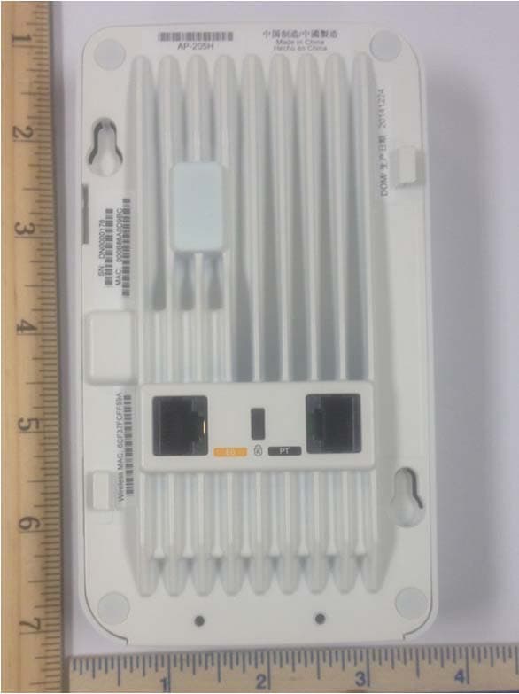
Click to zoom
Application Details
- Equipment Class
- NII - Unlicensed National Information Infrastructure TX
- Date of Grant
- Mar 16, 2015
- Application Purpose
- Original Equipment
- Date of Application
- Feb 12, 2015
- Equipment Note
- Hospitality Dual Band AP
- Frequency Range
- 5745.00000000 - 5825.00000000
- Country
- United States
Documents & Files
Document Text
Text extracted from the exhibit documents filed with the FCC. Open a document above to read the original.
Users Manual
Aruba AP-205H Wireless Access Point Installation Guide The Aruba AP-205H access point is a high-performance dual radio wireless and wired access point for hospitality and branch deployments. This device combines high-performance wireless mobility with Gigabit wired local access to deliver secure network access to dormitories, hotel rooms, classrooms, medical clinics, and multi-tenant environments. MIMO (Multiple-Input, Multiple-Output) technology enables the AP-205H to provide wireless 2.4 GHz 802.11n and 5 GHz 802.11n/ac functionality, while simultaneously supporting existing 802.11a/b/g wireless services. The AP-205H can be easily converted into a desk-mounted remote AP for branch office deployments with the AP-205H-MNTR mounting kit (sold separately), or attached to a wall box using the bracket included using the existing structured cable system. The AP-205H access point works in conjunction with an Aruba controller, while the IAP- 205H variant uses a built-in virtual controller. The Aruba AP-205H access point provides the following capabilities: zDual wireless transceivers zProtocol-independent networking functionality (no idea what this means) zIEEE 802.11a/b/g/n/ac operation as a wireless access point zIEEE 802.11a/b/g/n/ac operation as a wireless air monitor, spectrum analyzer zCompatibility with IEEE 802.3af/at PoE zCentral management configuration and upgrades through an Aruba Controller or Aruba Instant virtual controller POE power sourcing to an attached POE network device Support for selected USB peripherals Package Contents zAP-205H Access Point zSingle Gang Wall-box Mounting bracket z2x #6-32 Machine Screw zTorx Security Screw zInstallation Guide (this document) Hardware Overview Figure 1 Front LED The AP-205H is equipped with two LEDs indicating System Status and PSE. Figure 2 Rear Console Port The serial console port allows you to connect the AP to a serial terminal or a laptop for direct local management. This port located at the rear of the AP-205H, is a 4-pin connector with removable dust cover. An optional serial adapter cable (AP-CBL-SER) compatible with the AP-205H, is sold separately. Figure 3 Bottom Ethernet Ports AP-205H is equipped with a total of four active Ethernet ports (E0-E3). E0 is 10/100/1000 Base-T (RJ-45) auto-sensing, MDI/MDX wired-network uplink connectivity port that is primarily used as a passthrough port, but can alternatively serve as E0 if the E0 and PT ports are physically bridged by a jumper cable (sold separately with the AP-205H-MNTR RAP Conversion Kit). This port supports IEEE 802.3af Power over Ethernet (PoE), accepting 48VDC as a standard defined Powered Device (PD) from a Power Sourcing Equipment (PSE) such as a PoE midspan injector or network infrastructure that supports PoE. Ports E1-E3 are 10/100/1000 Base-T (RJ-45) auto-sensing, MDI/MDX wired-network downlink connectivity ports, used to provide secure network connectivity to wired devices. E0 is located on the rear of the AP, while the E1-E3 are located on the bottom (Figure 3). Additionally, AP-205H supports a passive pass-through RJ-45 interface to extend a physical connection (typically another Ethernet connection) from the back of the device to a connector on the bottom. Figure 4 Gigabit Ethernet Port Pin-Out USB Interface The AP-205H Series is equipped with a USB interface that is compatible with cellular modems and BLE dongles. When active, this USB port can supply up to 5W (1A). Power Supply The AP-205H has a single 48V DC power connector to support powering through an AC-to- DC power adapter. AP-AC-48V36 sold separately. When the AP-205H is powered by high-power, POE and POE-PSE on E3 is enabled and power to the powered device will be limited to 10W. When attempting to draw additional power, the AP will disable power on port E3. This port will automatically reactivate over time. Push Button The push button located on the right side of the AP can be used to reset the AP to factory default settings or turn off/on the LED display. zTo reset the AP to factory default settings: 1. Power off the AP. 2. Press and hold the push button using a small, narrow object, such as a paperclip. 3. Power-on the AP without releasing the push button. The system status LED will flash within 5 seconds. 4. Release the push button. The system status LED will flash again within 15 seconds indicating that the reset is completed. The AP will now continue to boot with the factory default settings. zTo turn off/on the system status LED: During the normal operation of the AP, press the push button using a small, narrow object, such as a paperclip. The system status LED will be turned off/on immediately. Before You Begin Pre-Installation Network Requirements After WLAN planning is complete and the appropriate products and their placement have been determined, the Aruba controller(s) must be installed and initial setup performed before the Aruba APs are deployed. AP Pre-Installation Checklist Before installing your AP-205H access point, be sure that you have the following: zPre-installed wall box zCat5E UTP cable with network access installed in the wall box zOne of the following power sources: IEEE 802.3af-compliant Power over Ethernet (PoE) source Aruba AP AC-DC adapter kit (sold separately) zAruba Controller provisioned on the network: Layer 2/3 network connectivity to your access point One of the following network services: zAruba Discovery Protocol (ADP) zDNS server with an “A” record zDHCP Server with vendor-specific options Summary of the Setup Process Complete each of tasks below in the order listed to setup your AP-205H access point. 1. Verify pre-installation connectivity. 2. Identify the specific installation location for each AP. 3. Install each AP. 4. Verify post-installation connectivity. 5.Configure each AP. Verifying Pre-Installation Connectivity Before you install APs in a network environment, make sure that the APs are able to locate and connect to the controller after power on. In order…
Text truncated - open the document above for the full version.
Cover Letter(s)
Page 1 of 1 National Technical Systems TCB 41039 Boyce Road Fremont, CA, 94538 FCC ID: Q9DAPINH205 To whom it may concern: The enclosed documents constitute a formal submittal and application for Equipment Authorization for a software defined radio pursuant to the following rules: Subpart C of Part 15 of FCC Rules (CFR 47) Subpart E of Part 15 of FCC Rules (CFR 47), UNII Devices The device is a dual radio 2.4GHz/5GHz 802.11b/g/a/n/ac indoor access point. The application is for the 2.4GHz DTS per 15.247, and UNII1 and UNII3 bands per 15.E, using the “new” FCC rules. The test report R97172 includes data for the 5.8GHz band. This data is intended for a future IC application. The test report R97173 includes results for the 5.8GHz band per FCC 15.407. The application is seeking approval as a software defined radio. National Technical Systems, as duly authorized agent prepared this submittal. A copy of the letter of our appointment as agent is included with the application. If there are any questions or if further information is needed, please contact National Technical Systems for assistance. Sincerely, Mark Hill Staff Engineer
External Photos
External Photos Front Rear Bottom Right Side Left Side Top
ID Label/Location Info
Label/Aruba 1 1 2015.01.21 1 Notes: 2.印刷顏色:如图 3.尺寸公差:0/-0.2mm 4.所使用材料需符合RoHS 1.材質:50番银色消银龙(銀色)+加强压花胶 +可打印雾面PET膜(需耐80°C高溫) COLOR OF BASE: MATERIAL PRIMARY COLOR OF FONT: BLACK SILVER MATT PET,T=0.05, BACKSIDE ADHESIVE MATERIAL 5. UL APPROVED INK & MATERIAL 6. REQUIREMENT FOR ADHESIVE GLUE: GRID ADHESIVE 20 mm 125 mm Aruba Networks, Inc Model: APINH205 IC: 4675A-APINH205 CMIIT ID: XXXXXXXX MOC: XX-XXXXX ETA-XXX/XXXX-RLO(SR)/XXXX ETA-XXX/XXXX-RLO(SR)/XXXX FCC ID: Q9DAPINH205 Aruba Networks, Inc Model: APINH205 IC: 4675A-APINH205 CMIIT ID: XXXXXXXX MOC: XX-XXXXX ETA-XXX/XXXX-RLO(SR)/XXXX ETA-XXX/XXXX-RLO(SR)/XXXX FCC ID: Q9DAPINH205
Internal Photos
Internal Photos
RF Exposure Info
EMC Test Data Client: Contact: Standard: Test Specific Details General Test Configuration Yes Device complies with Power Density requirements at 20cm ti Test Engineer: Mark Hill Calculation uses the free space transmission formula: S = (PG)/(4 πd 2 ) Where: S is power density (W/m 2 ), P is output power (W), G is antenna gain relative to isotropic, d is separation distance from the transmitting antenna (m). Summary of Results Maximum Permissible Exposure Objective: The objective of this test session is to perform final qualification testing of the EUT with respect to the specification listed above. Date of Test: 1/13/2015 Tian MendezProject Coordinator: - FCC 15.247/FCC 15.407/RSS-210/LP0002Class: N/A Aruba NetworksJob Number: J96879 Model: APINH205-2x2:2 MIMO 802.11a/b/g/n/ac Wireless Access Points T-Log Number: T96922 Project Manager: Christine Krebill Yes separation: Modifications Made During Testing No modifications were made to the EUT during testing Deviations From The Standard No deviations were made from the requirements of the standard. T96922 (FCC_Radio_2.4GHz_Conducted) MPE Calc_FCC_NonDFSPage 1 of 2 EMC Test Data Client: Contact: Standard: Tian MendezProject Coordinator: - FCC 15.247/FCC 15.407/RSS-210/LP0002Class: N/A Aruba NetworksJob Number: J96879 Model: APINH205-2x2:2 MIMO 802.11a/b/g/n/ac Wireless Access Points T-Log Number: T96922 Project Manager: Christine Krebill Use: General Antenna: 4dBi @ 2.4GHz, 6dBi @ 5GHz Peak AveragedBmWWdBm 2400 - 2483.5 OFDM-21.54.025.50.355 2401 - 2483.5 CCK-22.54.026.50.447 5150 - 5250 OFDM-20.26.026.20.41740-- 5725 - 5850 OFDM-20.76.026.70.468510.46826.70 20.91529.61 EIRP mW Worse case condition: 915 mW/cm^2mW/cm^2 0.1821.000 Worse case totals for simultaneous transmission: Power Densit y (S)MPE Limit at 20 cmat 20 cm Channels Available Channels Used Total EIRP 1110.44725.50 BandMode Output PowerAntenna gain (Max) EIRP T96922 (FCC_Radio_2.4GHz_Conducted) MPE Calc_FCC_NonDFSPage 2 of 2
Test Report
EMC Test Report Application for Grant of Equipment Authorization FCC Part 15, Subpart E Model: APINH205 2x2:2 MIMO 802.11a/b/g/n/ac Wireless Access Points FCC ID: Q9DAPINH205 APPLICANT: Aruba Networks 1344 Crossman Ave Sunnyvale, CA 94089 TEST SITE(S): National Technical Systems - Silicon Valley 41039 Boyce Road. Fremont, CA. 94538-2435 IC SITE REGISTRATION #: 2845B-3; 2845B-4, 2845B-5, 2845B-7 REPORT DATE: January 26, 2015 REISSUE DATE: February 10, 2015 FINAL TEST DATES: December 16, 17, 18, 19, 22 and 23, 2014 and January 5, 2015 TOTAL NUMBER OF PAGES: 118 PROGRAM MGR / QUALITY ASSURANCE DELEGATE / TECHNICAL REVIEWER: FINAL REPORT PREPARER: ______________________________ ______________________________ Mark E Hill David Guidotti Staff Engineer Senior Technical Writer National Technical Systems - Silicon Valley is accredited by the A2LA, certificate number 0214.26, to perform the test(s) listed in this report, except where noted otherwise. This report and the information contained herein represent the results of testing test articles identified and selected by the client performed to specifications and/or procedures selected by the client. National Technical Systems (NTS) makes no representations, expressed or implied, that such testing is adequate (or inadequate) to demonstrate efficiency, performance, reliability, or any other characteristic of the articles being tested, or similar products. This report should not be relied upon as an endorsement or certification by NTS of the equipment tested, nor does it represent any statement whatsoever as to its merchantability or fitness of the test article, or similar products, for a particular purpose. This report shall not be reproduced except in full File: R97173 Rev 1 Page 1 National Technical Systems - Silicon Valley Project number J96879 Report Date: January 26, 2015 Reissue Date: February 10, 2015 REVISION HISTORY Rev# Date Comments Modified By January 26, 2015 First release 1 February 10, 2015 Revised to correct model name David Guidotti Test Report R97173 Rev 1 Page 2 National Technical Systems - Silicon Valley Project number J96879 Report Date: January 26, 2015 Reissue Date: February 10, 2015 TABLE OF CONTENTS REVISION HISTORY ................................................................................................................................................ 2 TABLE OF CONTENTS ............................................................................................................................................ 3 SCOPE .......................................................................................................................................................................... 4 OBJECTIVE ................................................................................................................................................................ 4 STATEMENT OF COMPLIANCE ........................................................................................................................... 5 DEVIATIONS FROM THE STANDARDS .............................................................................................................. 5 TEST RESULTS SUMMARY ................................................................................................................................... 6 UNII / LELAN DEVICES ........................................................................................................................................ 6 GENERAL REQUIREMENTS APPLICABLE TO ALL BANDS .......................................................................... 7 MEASUREMENT UNCERTAINTIES .................................................................................................................... 8 EQUIPMENT UNDER TEST (EUT) DETAILS ...................................................................................................... 9 GENERAL ................................................................................................................................................................ 9 OTHER EUT DETAILS ........................................................................................................................................... 9 ANTENNA SYSTEM .............................................................................................................................................. 9 ENCLOSURE ........................................................................................................................................................... 9 MODIFICATIONS ................................................................................................................................................... 9 SUPPORT EQUIPMENT ....................................................................................................................................... 10 EUT INTERFACE PORTS .................................................................................................................................... 10 EUT OPERATION ................................................................................................................................................. 11 TEST SITE ................................................................................................................................................................. 12 GENERAL INFORMATION ................................................................................................................................. 12 CONDUCTED EMISSIONS CONSIDERATIONS .............................................................................................. 12 RADIATED EMISSIONS CONSIDERATIONS .................................................................................................. 12 MEASUREMENT INSTRUMENTATION ............................................................................................................ 13 RECEIVER SYSTEM ......................................................…
Text truncated - open the document above for the full version.
Test Setup Photos
Radiated Emissions Test Configuration Photographs Conducted Emissions Test Configuration Photographs
Contact Information
Applicant
Mark Hill(Principal Engineer)
Technical Contact
National Technical Systems - Silicon ValleyMark Hill
[email protected]5105783500
41039 Boyce Road · Fremont · United States
Test Firm
Element Materials Technology Fremont NewarkDavid Bare
Technical Specifications
| # | Rule Parts | Frequency Range | Power Output |
|---|---|---|---|
| 2 | 15E | 5.75 GHz - 5.83 GHz | 117.00 mW |
Other Applications from Hewlett Packard Enterprise Company
Q9DAPINH721
Jul 17, 2026Access Point
Equipment Class
6ID - 15E 6 GHz Low Power Indoor Access PointQ9DASIN0307
Dec 22, 2025HPE Aruba User Experience Sensor
Equipment Class
DTS - Digital Transmission SystemQ9DASIN0308
Nov 23, 2025HPE Aruba User Experience Sensor
Equipment Class
DTS - Digital Transmission SystemQ9DAPEX0764
Nov 20, 2025ACCESS POINT
Equipment Class
DTS - Digital Transmission SystemQ9DAPIN0763
Sep 29, 2025ACCESS POINT
Equipment Class
NII - Unlicensed National Information Infrastructure TX