Q9DARUBA52WLAN Dual Band Access Point
Hewlett Packard Enterprise Company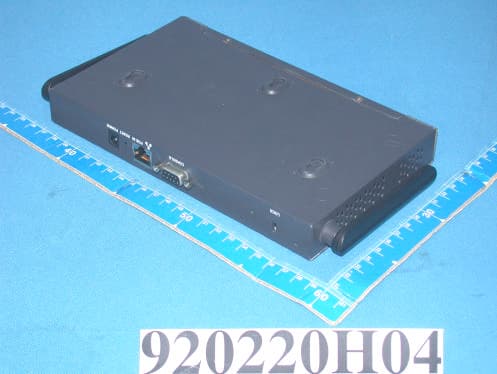
Click to zoom
Application Details
- Equipment Class
- NII - Unlicensed National Information Infrastructure TX
- Date of Grant
- Oct 06, 2003
- Application Purpose
- Original Equipment
- Date of Application
- Oct 06, 2003
- Equipment Note
- WLAN Dual Band Access Point
- Frequency Range
- 5725.00000000 - 5825.00000000
- Country
- United States
Documents & Files
Document Text
Text extracted from the exhibit documents filed with the FCC. Open a document above to read the original.
Users Manual
7/29/03 FINAL DRAFT—CONFIDENTIAL Aruba 52 Wireless Access Point Installation Guide TM 180 Great Oaks Blvd. Ste B San Jose, California 95119 Net www.arubanetworks.com Tel 408.227.4500 Fax 408.227.4550 7/29/03 FINAL DRAFT—CONFIDENTIAL ii Aruba 52Part 0500007B Installation GuideAugust 2003 Copyright Copyright © 2003 Aruba Wireless Networks, Inc. All rights reserved. Specifications in this manual are subject to change without notice. Originated in the USA. Trademarks Aruba 52, Aruba 5000, and AirOS are trademarks of Aruba Wireless Networks in the United States and certain other countries. The K & Lock design is a registered trademark of the Kensington Technology Group in the United States and certain other countries. Any other trademarks appearing in this manual are owned by their respective companies. Aruba 52 iii Installation Guide 7/29/03 FINAL DRAFT—CONFIDENTIAL Compliance FCC - Class B This equipment has been tested and found to comply with the limits for a Class B digital device, pursuant to Part 15 of the FCC Rules. These limits are designed to provide reasonable protection against harmful interference in a residential installation. This equipment generates, uses and can radiate radio frequency energy and, if not installed and used in accordance with instructions, may cause harmful interference to radio communications. However, there is no guarantee that the interference will not occur in a particular installation. If this equipment does cause harmful interference to radio or television reception, which can be determined by turning the equipment off and on, the user is encouraged to try to correct the interfer- ence by one or more of the following measures: zReorient the receiving antenna zIncrease the separation between the equipment and receiver zConnect the equipment into an outlet on a circuit different from that to which the receiver is connected zConsult the dealer or an experienced radio/TV technician for help FCC Caution: To assure continued compliance, use only shielded interface cables when connecting to computer or peripheral devices. Any changes or modifications not expressly approved by the party respon- sible for compliance could void the user’s authority to operate this equipment. This device complies with Part 15 of the FCC Rules. Operation is subject to the following two conditions: (1) This device may not cause harmful interference, and (2) this device must accept any interference received, including interference that may cause undesired operation. CAUTION STATEMENT: FCC RF Radiation Exposure Statement This equipment complies with FCC RF radiation exposure limits set forth for an uncontrolled environ- ment. This equipment should be installed and operated with a minimum distance of 20 centimeters (8 inches) between the radiator and your body. This transmitter must not be co-located or operating in con- junction with any other antenna or transmitter. Radio Frequency Interference Requirements This device is restricted to indoor use due to its operation in the 5.15 to 5.25 GHz frequency range. The FCC requires this product to be used indoors to reduce the potential for harmful interference to co-chan- nel Mobile Satellite systems. High power radars are allocated as primary users of the 5.25 to 5.35 GHz and 5.65 to 5.85 GHz bands. These radar stations can cause interference with and/or damage this device. Industry Canada - Class B This digital apparatus does not exceed the Class B limits for radio noise emissions from digital apparatus as set out in the interference-causing equipment standard entitled “Digital Apparatus,” ICES-003 of the Department of Communications. Cet appareil numérique respecte les limites de bruits radioélectriques applicables aux appareils numériques de Classe B prescrites dans la norme sur le matériel brouilleur: “Appareils Numériques,” NMB-003 édictée par le ministère des Communications. 7/29/03 FINAL DRAFT—CONFIDENTIAL iv Aruba 52Part 0500007B Installation GuideAugust 2003 Contents v 7/29/03 FINAL DRAFT—CONFIDENTIAL Contents Preface. . . . . . . . . . . . . . . . . . . . . . vii Related Documents . . . . . . . . . . . . . . . . . . vii Text Conventions . . . . . . . . . . . . . . . . . . viii Contacting Aruba Wireless Networks . . . . . . . . . . ix Chapter 1 Introduction . . . . . . . . . . . . . . . . . . . 1 Product Features . . . . . . . . . . . . . . . . . . . . 1 Ethernet Compatibility . . . . . . . . . . . . . . . 2 Radio Characteristics . . . . . . . . . . . . . . . . 2 Power Over Ethernet . . . . . . . . . . . . . . . . 2 Physical Description . . . . . . . . . . . . . . . . . . 3 Package Checklist . . . . . . . . . . . . . . . . . 3 Top Panel . . . . . . . . . . . . . . . . . . . . . 4 Rear Panel . . . . . . . . . . . . . . . . . . . . . 6 Chapter 2 Setup & Installation . . . . . . . . . . . . . 7 Requirements . . . . . . . . . . . . . . . . . . . . . 7 Select a Network Topology . . . . . . . . . . . . . . . 8 Perform Initial Setup . . . . . . . . . . . . . . . . . . 10 Direct SPOE to the Aruba WLAN Switch . . . . . 10 Direct Terminal Connection . . . . . . . . . . . . 13 Configure the Aruba 52 . . . . . . . . . . . . . . . 15 Mount the Aruba 52 . . . . . . . . . . . . . . . . . . 18 Free-Standing Placement . . . . . . . . . . . . . . 19 Using the Built-In Mounting Slots . . . . . . . . . 19 Using the Optional Mounting Kit . . . . . . . . . . 21 7/29/03 FINAL DRAFT—CONFIDENTIAL vi Aruba 52Part 0500007B Installation GuideAugust 2003 Connect Required Cables. . . . . . . . . . . . . . . . 25 Direct SPOE to the Aruba WLAN Switch . . . . . 25 LAN or POE Connection . . . . . . . . . . . . . . 26 Appendix A Port Specifications. . . . . . . . . . . . . 29 Console Port . . . . . . . . . . . . . . . . . . . . . . 29 FE Port . . . . . . . . . . . . . . . . . . . . . . . . 30 SPOE Adapter . . . . . . . . . . . . . . . . . . . . . 31 Appendix B Product Specifications. . . . . . . . . . 33 Preface vii 7/29/03 FINAL DRAFT—CONFIDENTIAL Preface The prefa…
Text truncated - open the document above for the full version.
Cover Letter(s)
Page 1 of 3 RE: Aruba Networks FCC ID: Q9DARUBA52 1) Certain documents appear to be uploaded as confidential (block diagram & schematics) however a confidentiality letter was not provide. Please explain or provide this letter. Response: Confidentiality Letter has been uploaded. 2) The labeling information appears to also be labeled for a DoC. It is assumed this is for the PC peripheral part of the device. However the labeling is missing the appropriate FCC logo. Please update the labeling. Response: New label has been uploaded. 3) The antenna appears to contain 2 RF cable, one for 2.4 GHz and one for 5 GHz. Is the internal construction of the antenna actually contain 2 separate antennas, or is there a shared antenna internally. Please provide close up internal photographs of the antenna construction to show whether the antennas are separate or not internally. Note that a shared antenna would suggest a concern with mixing of both the 2.4 and 5 GHz signals, therefore creating inter-modulation concerns if they operate at the same time and share the same RF antenna. Response: Photos of antenna has been uploaded to RF exposure exhibit. The device will not transmit simultaneously. 4) The RF exposure shows separate calculations for each mode of operation (802.11b, 802.11a, 802.11a turbo, etc.). Please explain if this device (under normal use by the user) may transmit simultaneously using both 802.11b and 802.11a. If so, please update the RF exposure to show the composite RF exposure condition that can occur. Response: The device will not transmit simultaneously under normal use. 5) Please provide test configuration photographs available for the AC power line conducted tests. Response: Test photos of AC conducted have been uploaded. DTS Report 6) Page 8 of 18 of the DTS report states that the antenna is a standard N-type connector and that this is professionally installed. This device does not appear to be professionally installed and additionally does not appear to contain an N-connector (see information on page 3 of 29, DTS Report). Please explain and correct the report if necessary. Response: Statement has been corrected. 7) Page 23 of 62 of the DTS test report appears incomplete. Please explain. Response: This has been removed since it a summary for our internal lab tests. Page 2 of 3 8) The power spectral density given on page 5 of 18, DTS report does not match the data given on page 12 of 29. Response: The worst case PSD from 802.11b and 802.11g was reported. I have revised the report to include both PSD from each mode. 9) The Fundamental measurements made for peak and average measurements on page 7, 8, 9, 19, 20, 21 of 29 should have been measured with RBW=VBW=1 MHz for Peak and RBW=1 MHz & VBW = 10 Hz for Average. However the table on each page states a 100 kHz was used. Please correct as appropriate. Response: All Fundamental measurements were made with RBW=VBW=1MHz (Peak), RBW=1MHz & VBW=10Hz (Avg). The report states what settings were used. 10) Please explain why the 3 rd bandwidth plot does not show the standard DSS envelope typically seen in the previous 2 bandwidth plots for pages 11 & 23. Additionally, the results for the High channel on page 25 appear unusually low. Please explain. Response: New plots of this have been uploaded. Results on page 25 for the high channel are not the same due to the spike not being present during the 100 sec sweep, but it is present on the first two plots. 11) This test report contains 2 complete sets of radiated data for 2.4 GHz (1 st starts on page 5, second on page 17). However there is no explanation between these sets of data. Please explain the purpose of both sets of data. Response: This has been corrected. 1 st set of data is for 802.11g mode and 2 nd set of data is for 802.11b mode. The worst-case radiated margin from both modes was reported only. 12) The resolution correction given on page 18 is only valid if correcting for a RBW from 1 MHz to 100 kHz (approximately 1%) and the VBW stays constant. Please provide information for the RBW and VBW used for both traces shown on this plot. Additionally, this correction appears to only be applied to one data point on page 19 and two data points on page 22. These data points should be adjusted as necessary in the comments column to show the appropriate correction factor for these points. Response: This has been corrected. RBW and VBW used for the BW correction plot are included. UNII Report 13) The users manual does not appear to contain the information to the user regarding 15.407(e). Response: New User Manual has been uploaded with the proper statements. 14) There has been some concern regarding the use of peak power meters for certain modulations and bandwidth signals. Please provide Peak power data in accordance to one of the methods given in the FCC Public Notice DA 02-2138. Response: New Power plots with Spectrum analyzer has been included. 15) The resolution correction given on page 5 of 48 is only valid for restricted band measurements if correcting for a RBW from 1 MHz to approximately 1% of the bandwidth of the fundamental and the VBW stays constant. It appears that 100 kHz was used and a RBW should have been approximately >= 200 kHz from the information given on page 13 of 48. Please provide a corrected bandwidth correction plot and be sure to include information for the RBW and VBW used for both traces shown. Additionally, when this correction is applied, the data points associated with this correction should be adjusted as necessary in the comments column to show the appropriate correction factor for these points. This issue will affect the 4 reported results for 5150 MHz and the results reported on page 4 of 48. Page 3 of 3 Response: New plot with RBW= 200kHz has been included. 16) Please provide PSD data for the high channel in the 5.150-5.250 Band. Response: This has been included in the report as requested. 17) Does this device contain a turbo mode which incorporates a different ch…
Text truncated - open the document above for the full version.
Cover Letter(s)
Tim, Here are my response: 1) The new labeling provided appears to now be missing all the DoC information. From previous review of this device it appears that the DoC labeling should be present, but was incomplete. Response: The device was tested as a network peripheral and not a computer peripheral so we are submitting as a verification device and not a DoC, that is why the Label was re-submitted to only show verification FCC statement. 2) The new UNII power measurements do not appear to follow method 3 specified in accordance to the methods given in the FCC Public Notice DA 02-2138. For example, the plot does not appear to be max held for 60 seconds. Additionally, please justify the use of 300 kHz for this measurement (is VBW >= 1/T where T is the transmission pulse duration?). If necessary, please update the report, 731 form, and MPE calculations. Response: Per the FCC Public notice we used sampling mode (if sample detector mode if bin width (i.e., span/number of points in spectrum) < 0.5 RBW, which we know is less then 0.5 RBW). The problem with our analyzer 8564E, which is the only one with Channel Power integration option, is that when we set to sampling mode and try to max hold the trace, the analyzer returns the state back to peak mode, so what we done is set the analyzer to single sweep and continuos sweep. We switch between these two modes for several sweeps to determine the worst case amplitude within at least 30 sec period. If this is not acceptable please let me know and we will try something else and re-submit new data. Page 13 of 48 of the test data states the reasoning for using a VBW of 300kHz. Below is the statement we placed in the page I just mentioned: The minimum VBW required for power measurements using a spectrum analyzer is 1/T, where T is the pulse transmission rate. Pulse Transmission Rate: 4.0 uS (Symbol Rate for 802.11a) Minimum VBW: 250 kHz VBW Used: 300 kHz (Used Method# 3 from the UNII FCC Public Notice) The minimum VBW required for power measurements using a spectrum analyzer is 1/T, where T is the pulse transmission rate. 3) Please justify the use of an averaging detector for page 48 of the UNII report measurements. The limit is a peak limit and should therefore utilize same settings as peak power measurements (using method #3 for power measurements RBW = 1 MHz, VBW >= 1/T, max hold for 60 sec, etc.). This does not To: [email protected] Subject: Aruba Networks, FCC ID: Q9DARUBA52 Cc: Documentation Group <[email protected]>, Christine Vu <[email protected]> Page 1 of 2In 9/24/2003Printed for "Timothy R. Johnson" <[email protected]> appear to have been done. Response: We will like to know what the FCC interpretation is on this, since there is not mention of what settings to use for the 5.725 to 5.825 MHz Bandedge range in the FCC Public Notice for the UNII. We have so far used the interpretation were if a signal is continuously transmitting and that is not the normal function of the transmitter, Average is allowed in this scenario, while using an RBW and VBW of 1MHz. If the case is that FCC is not allowing this, we will like to know what is their new thinking on this, especially for the UNII devices. Anything else please let me know. Thanks Regards, Juan Martinez EMC Engineer Elliott Labratories Page 2 of 2In 9/24/2003Printed for "Timothy R. Johnson" <[email protected]>
Cover Letter(s)
Page 1 of 1 RE: Aruba Networks FCC ID: Q9DARUBA52 1) Because of the concerns noted regarding the sampling mode, it would be suggested to use method 3 with the peak detector/max hold/60 seconds method mentioned. Response: Plots of power have been re-measured in peak mode and hold for 60 sec. Revised report with new data has been included. Also, a revised MPE has been uploaded. 2) To continue with your response regarding your question to item 3, please clarify the following: It appears that you used video averaging. Please clarify if the detector was set to peak, sample, or average with video averaging on during these measurements. Also, please confirm if the device was transmitting continuously or if there was a TX On/Off time occurring as could be implied by page 13 of 48 in the test report. Response: Detector was set to sampling mode of at least 100 sweeps. The TX On/Off, mention in page 13 of 48, is the normal pulse rate of the 802.11a radio in normal use...for test purposes the radio was force to transmit continuously. Hopefully this answers all of your questions. Please contact me [email protected] you require more information. Regards, Juan Martinez Sr. EMC Engineer
Cover Letter(s)
American Telecommunications Certification Body Inc. 6731 Whittier Ave, McLean, VA 22101 July 18, 2003 RE: Aruba Networks FCC ID: Q9DARUBA52 After a review of the submitted information, I have a few comments on the above referenced Application. 1) Certain documents appear to be uploaded as confidential (block diagram & schematics) however a confidentiality letter was not provide. Please explain or provide this letter. 2) The labeling information appears to also be labeled for a DoC. It is assumed this is for the PC peripheral part of the device. However the labeling is missing the appropriate FCC logo. Please update the labeling. 3) The antenna appears to contain 2 RF cables, one for 2.4 GHz and one for 5 GHz. Is the internal construction of the antenna actually contain 2 separate antennas, or is there a shared antenna internally. Please provide close up internal photographs of the antenna construction to show whether the antennas are separate or not internally. Note that a shared antenna would suggest a concern with mixing of both the 2.4 and 5 GHz signals, therefore creating inter-modulation concerns if they operate at the same time and share the same RF antenna. 4) The RF exposure shows separate calculations for each mode of operation (802.11b, 802.11a, 802.11a turbo, etc.). Please explain if this device (under normal use by the user) may transmit simultaneously using both 802.11b and 802.11a. If so, please update the RF exposure to show the composite RF exposure condition which can occur. 5) Please provide test configuration photographs available for the AC power line conducted tests. DTS Report 6) Page 8 of 18 of the DTS report states that the antenna is a standard N-type connector and that this is professionally installed. This device does not appear to be professionally installed and additionally does not appear to contain an N-connector (see information on page 3 of 29, DTS Report). Please explain and correct the report if necessary. 7) Page 23 of 62 of the DTS test report appears incomplete. Please explain. 8) The power spectral density given on page 5 of 18, DTS report does not match the data given on page 12 of 29. 9) The Fundamental measurements made for peak and average measurements on page 7, 8, 9, 19, 20, 21 of 29 should have been measured with RBW=VBW=1 MHz for Peak and RBW=1 MHz & VBW = 10 Hz for Average. However the table on each page states a 100 kHz was used. Please correct as appropriate. 10) Please explain why the 3 rd bandwidth plot does not show the standard DSS envelope typically seen in the previous 2 bandwidth plots for pages 11 & 23. Additionally, the results for the High channel on page 25 appear unusually low. Please explain. 11) This test report contains 2 complete sets of radiated data for 2.4 GHz (1 st starts on page 5, second on page 17). However there is no explanation between these sets of data. Please explain the purpose of both sets of data. 12) The resolution correction given on page 18 is only valid if correcting for a RBW from 1 MHz to 100 kHz (approximately 1%) and the VBW stays constant. Please provide information for the RBW and VBW used for both traces shown on this plot. Additionally, this correction appears to only be applied to one data point on page 19 and two data points on page 22. These data points should be adjusted as necessary in the comments column to show the appropriate correction factor for these points. --- Continued on Next page --- z Page 2July 18, 2003 UNII Report 13) The users manual does not appear to contain the information to the user regarding 15.407(e). 14) There has been some concern regarding the use of peak power meters for certain modulations and bandwidth signals. Please provide Peak power data in accordance to one of the methods given in the FCC Public Notice DA 02-2138. 15) The resolution correction given on page 5 of 48 is only valid for restricted band measurements if correcting for a RBW from 1 MHz to approximately 1% of the bandwidth of the fundamental and the VBW stays constant. It appears that 100 kHz was used and a RBW should have been approximately >= 200 kHz from the information given on page 13 of 48. Please provide a corrected bandwidth correction plot and be sure to include information for the RBW and VBW used for both traces shown. Additionally, when this correction is applied, the data points associated with this correction should be adjusted as necessary in the comments column to show the appropriate correction factor for these points. This issue will affect the 4 reported results for 5150 MHz and the results reported on page 4 of 48. 16) Please provide PSD data for the high channel in the 5.150-5.250 Band. 17) Does this device contain a turbo mode which incorporates a different channel set and should require testing? 18) Peak excursion measurements do not appear to show Trace A with RBW = 1 MHz and VBW >= 3 MHz according to FCC Public Notice DA 02-2138. 19) Page 48 does not appear to take into consideration the 4.5 dBi gain for the antenna in the limit (limit = -17 dBm - 4.5 = 21.5 dBm) in the UNII band nor does the measurement appear to factor in this correction. It appears this device may fail this test. 20) The application does not appear to provide any information regarding 15.407(c) & (g). Timothy R. Johnson Examining Engineer mailto: [email protected] The items indicated above must be submitted before processing can continue on the above referenced application. Failure to provide the requested information may result in application termination. Correspondence should be considered part of the permanent submission and may be viewed from the Internet after a Grant of Equipment Authorization is issued. Please do not respond to this correspondence using the email reply button. In order for your response to be processed expeditiously, you must submit your documents through the AmericanTCB.com website. Also, please note that partial responses increase processing time and should not be submitte…
Text truncated - open the document above for the full version.
Cover Letter(s)
American Telecommunications Certification Body Inc. 6731 Whittier Ave, McLean, VA 22101 September 16, 2003 RE: Aruba Networks FCC ID: Q9DARUBA52 After a review of the submitted information, I have a few comments on the above referenced Application. 1) The new labeling provided appears to now be missing all the DoC information. From previous review of this device it appears that the DoC labeling should be present, but was incomplete. 2) The new UNII power measurements do not appear to follow method 3 specified in accordance to the methods given in the FCC Public Notice DA 02-2138. For example, the plot does not appear to be max held for 60 seconds. Additionally, please justify the use of 300 kHz for this measurement (is VBW >= 1/T where T is the transmission pulse duration?). If necessary, please update the report, 731 form, and MPE calculations. 3) Please justify the use of an averaging detector for page 48 of the UNII report measurements. The limit is a peak limit and should therefore utilize same settings as peak power measurements (using method #3 for power measurements RBW = 1 MHz, VBW >= 1/T, max hold for 60 sec, etc.). This does not appear to have been done. Timothy R. Johnson Examining Engineer mailto: [email protected] The items indicated above must be submitted before processing can continue on the above referenced application. Failure to provide the requested information may result in application termination. Correspondence should be considered part of the permanent submission and may be viewed from the Internet after a Grant of Equipment Authorization is issued. Please do not respond to this correspondence using the email reply button. In order for your response to be processed expeditiously, you must submit your documents through the AmericanTCB.com website. Also, please note that partial responses increase processing time and should not be submitted. Any questions about the content of this correspondence should be directed to the sender.
Cover Letter(s)
American Telecommunications Certification Body Inc. 6731 Whittier Ave, McLean, VA 22101 September 25, 2003 RE: Aruba Networks FCC ID: Q9DARUBA52 After a review of the submitted information, I have a few comments on the above referenced Application. 1) Because of the concerns noted regarding the sampling mode, it would be suggested to use method 3 with the peak detector/max hold/60 seconds method mentioned. 2) To continue with your response regarding your question to item 3, please clarify the following: It appears that you used video averaging. Please clarify if the detector was set to peak, sample, or average with video averaging on during these measurements. Also, please confirm if the device was transmitting continuously or if there was a TX On/Off time occurring as could be implied by page 13 of 48 in the test report. Timothy R. Johnson Examining Engineer mailto: [email protected] The items indicated above must be submitted before processing can continue on the above referenced application. Failure to provide the requested information may result in application termination. Correspondence should be considered part of the permanent submission and may be viewed from the Internet after a Grant of Equipment Authorization is issued. Please do not respond to this correspondence using the email reply button. In order for your response to be processed expeditiously, you must submit your documents through the AmericanTCB.com website. Also, please note that partial responses increase processing time and should not be submitted. Any questions about the content of this correspondence should be directed to the sender.
External Photos
Page 1 CONSTRUCTION PHOTOS OF EUT
ID Label/Location Info
ARUBA WIRELESS NETWORKS INC. TITLE: LABEL,AGENCY,ACCESS POINT DWG NO: 4000033REV 02 . ARUBA WIRELESS NETWORKS INC. This device complies with Part 15 of the FCC Rules. Operation is subject to the following two conditions: (1) This device may not cause harmful interference, and (2) This device must accept any interference received, including interference that may cause undesired operation. MODEL #: ARUBA 52 0560 FCC ID:Q9DARUBA52 Complies with RSS-210 ICES-003 CLASS B INPUT VOLTAGE 3.3V dc ,3A 60.0 mm 42.0 mm Mater ial: metalized + Glossy Polyester thickness: .2 mm Adhesive: UL Approved - Acr ylic Text color: B lack R 2.5 4 places ! E234335 I.T .E. RXXXXXXX RXXXXXXX RXXXXXXX
Internal Photos
Page 1 CONSTRUCTION PHOTOS OF EUT Page 2 Page 3 Page 4 Page 5 Page 6 Page 7 Page 8 Page 9 Page 10
RF Exposure Info
MPE Calculations FCC part 1.1310, Table 1 limits the power density for uncontrolled exposure to 1mW/ cm 2 for systems operating in the DTS and UNII bands. The distance, d(cm) from the antenna at which the power density, P d (mW/cm 2 ) is below this limit is calculated from the maximum EIRP, P t (mW) using the equation: P d =P t /(4πd 2 ) Re-arranging for the distance at whichthe power density is 1mW/cm2 gives: d=√(P t /(4π)) Frequency Maximum Output Power (dBm) Max. Antenna Gain (dBi) EIRP (mW) Pd at 20cm Calculated distance (in cm) where Pd < 1mW/ cm2 2412 - 2462 MHz 19.51.5125.890.0253.16 5180 - 5320 MHz 15.04.589.10.0182.66 5745 - 5805 MHz 16.34.5120.20.0243.09 The minimum distance from the antenna that the power density is 1mW/ cm 2 and the calculated minimum distance is 3.16 cm, for 2.4GHz, and 3.09 cm, for 5 GHz).
Test Report
File: R51621 June 20, 2003 American TCB 6731 Whittier Ave. Suite C110 McLean VA. 22101 Gentlemen: The enclosed documents constitute a formal submittal and application for a Grant of Equipment Authorization pursuant to Subpart E of Part 15 of FCC Rules (CFR 47) regarding intentional radiators. Data within this report demonstrates that the equipment tested complies with the FCC limits for intentional radiators. Elliott Laboratories, as duly authorized agent prepared this submittal. A copy of the letter of our appointment as agent is enclosed. If there are any questions or if further information is needed, please contact Elliott Laboratories for assistance. Sincerely, Mark Briggs Director of Engineering MB/dmg Enclosures: Agent Authorization Letter Emissions Test Report with Exhibits File: R51621 Page 1 of 18 Electromagnetic Emissions Test Report and Application for Grant of Equipment Authorization pursuant to FCC Part 15, Subpart E (UNII Devices) on the Aruba Networks Model: Aruba 52 FCC ID: Q9DARUBA52 GRANTEE: Aruba Networks 180 Great Oaks San Jose, CA 95119 TEST SITE: Elliott Laboratories, Inc. 684 W. Maude Avenue Sunnyvale, CA 94086 REPORT DATE: June 20, 2003 FINAL TEST DATE: June 10 and June 11, 2003 AUTHORIZED SIGNATORY: ______________________________ Mark Briggs Director of Engineering Elliott Laboratories, Inc. is accredited by the A2LA, certificate number 2016-01, to perform the test(s) listed in this report. This report shall not be reproduced, except in its entirety, without the written approval of Elliott Laboratories, Inc. Elliott Laboratories, Inc. -- EMC Department Test Report Report Date: June 20, 2003 File: R51621 Page 2 of 18 Pages DECLARATIONS OF COMPLIANCE Equipment Name and Model: Aruba 52 Manufacturer: Aruba Networks 180 Great Oaks San Jose, CA 95119 Tested to applicable standards: RSS-210, Issue 5, November 2001 (Low Power License-Exempt Radiocommunication Devices) FCC Part 15 Subpart E (UNII Devices) Departmental Acknowledgement Number: IC2845 SV2 Dated August 12, 2001 Departmental Acknowledgement Number: IC2845 SV4 Dated July 19, 2001 I declare that the testing was performed or super…
Text truncated - open the document above for the full version.
Contact Information
Applicant
Mark Hill(Principal Engineer)
Technical Contact
Elliott Laboratories Inc.Juan Martinez
[email protected]408-245-7800
684 West Maude Ave. · Sunnyvale, California · United States
Non-Technical Contact
Elliott Laboratories Inc.Juan Martinez
[email protected]408-245-7800
Test Firm
Elliott Laboratories LLCDavid Bare
Technical Specifications
| # | Rule Parts | Frequency Range | Power Output |
|---|---|---|---|
| 2 | 15E | 5.72 GHz - 5.83 GHz | 43.00 mW |
Other Applications from Hewlett Packard Enterprise Company
Q9DAPINH721
Jul 17, 2026Access Point
Equipment Class
6ID - 15E 6 GHz Low Power Indoor Access PointQ9DASIN0307
Dec 22, 2025HPE Aruba User Experience Sensor
Equipment Class
DTS - Digital Transmission SystemQ9DASIN0308
Nov 23, 2025HPE Aruba User Experience Sensor
Equipment Class
DTS - Digital Transmission SystemQ9DAPEX0764
Nov 20, 2025ACCESS POINT
Equipment Class
DTS - Digital Transmission SystemQ9DAPIN0763
Sep 29, 2025ACCESS POINT
Equipment Class
NII - Unlicensed National Information Infrastructure TX