Q9DARUBA60802.11 .a/.b/.g Access Point
Hewlett Packard Enterprise Company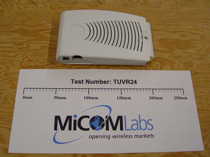
Click to zoom
Application Details
- Equipment Class
- NII - Unlicensed National Information Infrastructure TX
- Date of Grant
- Sep 07, 2004
- Application Purpose
- Original Equipment
- Date of Application
- Sep 07, 2004
- Equipment Note
- 802.11 .a/.b/.g Access Point
- Frequency Range
- 5725.00000000 - 5825.00000000
- Country
- United States
Documents & Files
Document Text
Text extracted from the exhibit documents filed with the FCC. Open a document above to read the original.
Users Manual
Aruba 60/61 Wireless Access Point Installation Guide TM 60 61 ii Aruba 60/61Part 0500034 Installation GuideJuly 2004 Copyright Copyright © 2004 Aruba Wireless Networks, Inc. All rights reserved. Specifications in this manual are subject to change without notice. Originated in the USA. Trademarks Aruba AP60, Aruba AP61, Aruba 5000, Aruba 2400, Aruba 800, and AirOS are trademarks of Aruba Wireless Networks in the United States and certain other countries. The K & Lock design is a registered trademark of the Kensington Technology Group in the United States and certain other countries. Any other trademarks appearing in this manual are owned by their respective companies. Contents iii Contents Chapter 1Introduction . . . . . . . . . . . . . . . . . . . 1 Front View . . . . . . . . . . . . . . . . . . . . . 2 Back View . . . . . . . . . . . . . . . . . . . . . 4 The Aruba AP Setup Process . . . . . . . . . . . . . . 5 Chapter 2 Provisioning Access Points . . . . . . . 7 Aruba Discovery Protocol . . . . . . . . . . . . . . . . 8 AP Reprovisioning . . . . . . . . . . . . . . . . . 9 AP Provisioning . . . . . . . . . . . . . . . . . . . . 10 Manual Provisioning . . . . . . . . . . . . . . . . . . 14 Requirements . . . . . . . . . . . . . . . . . . . 14 Connecting the Console Terminal . . . . . . . . . . . . 15 Console Access to the AP . . . . . . . . . . . . . . 15 Setting Aruba 60/61 Parameters . . . . . . . . . . . . 18 Chapter 3 AP Deployment . . . . . . . . . . . . . . . 23 Mounting the Aruba 60/61 . . . . . . . . . . . . . . . 23 Aruba AP60 Detachable Antennas . . . . . . . . . 24 Free-Standing Placement . . . . . . . . . . . . . . 25 Using the Built-In Mounting Slots . . . . . . . . . 26 Using the Optional Mounting Kits . . . . . . . . . 27 Connecting Required Cables . . . . . . . . . . . . . . 28 Selecting an FE Cable . . . . . . . . . . . . . . . 28 Connecting Cables & Power . . . . . . . . . . . . 29 iv Aruba 60/61Part 0500034 Installation GuideJuly 2004 Appendix APort Specifications. . . . . . . . . . . . . 31 FE Port . . . . . . . . . . . . . . . . . . . . . . . . 31 Serial Breakout Adapter . . . . . . . . . . . . . . . . 32 DB-9 Specification . . . . . . . . . . . . . . . . . 33 “To AP” Specifications . . . . . . . . . . . . . . . 33 “To Network” Specifications . . . . . . . . . . . . 33 Appendix B Troubleshooting . . . . . . . . . . . . . . . 35 Accessing the AP Support Prompt . . . . . . . . . . . 35 Direct SPOE Connection to WLAN Switch . . . . . 35 Direct Terminal Connection . . . . . . . . . . . . 36 Remote Telnet Connection . . . . . . . . . . . . . 37 AP Support . . . . . . . . . . . . . . . . . . . . . . 38 Access Levels . . . . . . . . . . . . . . . . . . . 38 User Commands . . . . . . . . . . . . . . . . . . 38 Privileged Commands . . . . . . . . . . . . . . . 38 Appendix C Product Specifications. . . . . . . . . . 39 Compliance . . . . . . . . . . . . . . . . . . . . . . 39 Certifications . . . . . . . . . . . . . . . . . . . . . . 41 Product Features . . . . . . . . . . . . . . . . . . . . 42 Ethernet Compatibility . . . . . . . . . . . . . . . 42 Radio Characteristics . . . . . . . . . . . . . . . . 42 Power Over Ethernet . . . . . . . . . . . . . . . . 43 Physical Description . . . . . . . . . . . . . . . . . . 43 Package Contents . . . . . . . . . . . . . . . . . . 43 Optional Items . . . . . . . . . . . . . . . . . . . 43 Aruba AP-60 Access Point . . . . . . . . . . . . . . . 44 Aruba AP-61 Access Point . . . . . . . . . . . . . . . 50 Related Documents . . . . . . . . . . . . . . . . . . . 56 Text Conventions . . . . . . . . . . . . . . . . . . . 57 Contacting Aruba Wireless Networks . . . . . . . . . . 58 Notes . . . . . . . . . . . . . . . . . . . . . . . 59 Introduction 1 Chapter 1 CHAPTER 1 Introduction The Aruba 60/61 is part of a comprehensive wireless network solution. The device works in conjunction with the Aruba WLAN Switch and can act as a wireless access point or air monitor. As a wireless Access Point (AP), the Aruba 60/61 provides transparent, secure, high-speed data communications between wireless network devices (fixed, portable, or mobile computers with IEEE 802.11a or IEEE 802.11b/g wireless adapters) and the wired LAN. As a wireless Air Monitor (AM), a feature unique to Aruba products, the Aruba 60/61 enhances wireless networks by collecting statistics, monitoring traffic, detecting intrusions, enforcing security policies, balancing wireless traffic load, self-healing coverage gaps, and more. NoteInstalling the AP 60/61 requires setting the antenna power, which requires profes- sional training. The AP60/61 installer must be trained to perform this configura- tion. 2Aruba60/61Part 0500034 Installation GuideJuly 2004 Front View FIGURE1-1 Aruba 60/61 Front View 1 2 3 4 5 AB CBA Introduction 3 Chapter 1 Antenna fixtures for Wireless Communications Depending on the model, the AP will have one of the following: Aruba AP60–Two Reverse Polarity SMA (RP-SMA) connectors for attaching separate antennas (not included). For details, see “Aruba AP60 Detachable Antennas” on page 24. Aruba AP61–Built-in swivel array with dual, tri-band, omnidirectional antennas Indicator LEDs During operation, the Aruba 60/61 LEDs provide the following information: NoteLEDs on the Aruba WLAN Switch provide additional status and security informa- tion about connected APs.See the Aruba AirOS User Guide for more information. Air Vents These vents promote proper air circulation for cooling the device. Do not allow these vents to be obstructed by mounting equipment, network cables, or any other material. FE Port This port attaches the Aruba 60/61 to a 10Base-T/100Base-TX (twisted-pair) Ethernet LAN segment. This port also supports Serial and Power Over Ethernet (SPOE). See Appendix A for port and cable specifications. TABLE1-1Aruba 60/61 LEDs LEDStateDescription PWROffThe device is off - no power. Green-Solid The device is powered and operating. ENETOffNo link on the FE port. No connect…
Text truncated - open the document above for the full version.
Users Manual
AP Deployment 23 Chapter 3 CHAPTER 3 AP Deployment This chapter covers the following topics: zPhysical mounting of the Aruba 60/61 zConnecting the required cables Mounting the Aruba 60/61 When provisioning is complete, mount the Aruba 60/61 at its intended service location. The Aruba 60/61 Access Points with or without external antennas are intended only for installation in Environment A as defined in IEEE 802.3.af. All interconnected equipment must be contained within the same building, including the interconnected equipment's associated LAN connections. Select a location as close as possible to the center of the intended coverage area. If necessary, use the Aruba RF Plan site survey tool to determine the optimum locations for your access points and air monitors. The service location should be free from obstructions or obvious sources of interference. Normally, the higher you place an access point or air monitor, the better its performance. If external antennas are used, make sure that they and their associated wiring are located entirely indoors. TheAruba 60/61 and any optional external antennas are not suitable for outside use. 24 Aruba 60/61Part 0500034 Installation GuideJuly 2004 The Aruba 60/61 can be mounted on a wall or suspended from above (not shown) using one of the optional mounting kits (dimensions vary) in the following ways: FIGURE3-1 Aruba 60/61 Mounting Options NoteFor dimensions, see “Product Specifications”. Allow 5 cm (2") additional space on the right-hand side for cables. Measurements for the Aruba AP60 depend on attached antennas, which vary. Aruba AP60 Detachable Antennas Before deploying the Aruba AP60, attach the appropriate antennas (not included). The antenna connections should be tightened by hand to avoid overtightening. The Aruba AP60 has dual Reverse Polarity SMA (RP-SMA) female antenna connectors that accept a variety of high-gain detachable antennas. A list of antennae tested for use with the Aruba AP60 is available on the Aruba Wireless Networks Web site: http://www.arubanetworks.com Check the Interoperability section of the Products page for the latest information. NoteOther antennae not listed may also work with the Aruba AP60, but for RF regulatory purposes should only be used if they are rated at a lower gain than similar, listed antennae. 12 3 AP Deployment 25 Chapter 3 Make sure that all external antennas and their associated wiring are located entirely indoors. The Aruba AP60 Access Points and their optional external antennas are not suitable for outside use. Free-Standing Placement To place the Aruba 60/61 indoors on a flat table or shelf: 1Flip open the stand located on the back of the Aruba 60/61: FIGURE3-2 Aruba 60/61Fold-Out Stand 2Place the device on a sturdy table or shelf. 3Orient the antennas. For best performance, swivel the individual antennas (Aruba AP60) or antenna array (Aruba AP61) so that they are oriented vertically. Once mounting is complete, connect the required cables (see instructions on page 28). CAUTION—Do not place the Aruba 60/61 in any place where it could fall on people or equipment. For more secure installation, use one of the optional mounting kits. 26 Aruba 60/61Part 0500034 Installation GuideJuly 2004 Using the Built-In Mounting Slots The keyhole-shaped slots on the back of the Aruba 60/61 can be used to attach the device upright to an indoor wall or shelf. To hang the Aruba 60/61 upright using the mounting slots, perform the following steps. 1Install two screws in the wall or shelf as shown in Figure 3-3: FIGURE3-3 Mounting Screw Specifications If attaching the device to drywall, we recommend using appropriate wall anchors (not included) as shown in Figure 3-4 on page 27. CAUTION—Do not use the mounting slots to hang the Aruba 60/61 from the ceiling, sideways, or in any place where it could fall on people or equip- ment. For more secure installation, use one of the optional mounting kits. Screw/Nail Positions (fastened to wall or shelf) 12.7 cm (5.00") 0.12" 0.27" 0.23" 0.05" clearance from surface 3.0 mm 5.8 mm 0.08" 0.15" clearance from surface 2.0 mm 3.8 mm clearance from surface 1.3 mm clearnace from surface 7.0 mm MaximumMinimum Screw/Nail Dimensions AP Deployment 27 Chapter 3 2Align the Aruba 60/61 mounting slots to capture the surface screws. FIGURE3-4 Hanging the Aruba 60/61 on Screws 3Secure the Aruba 60/61, if desired. To prevent the unauthorized removal of the Aruba 60/61 from its installed location, use a Kensington MicroSaver Security Cable (not included). Wrap the security cable around an immovable object, insert the cable’s lock into the Kensington Security Slot on the back of the Aruba 60/61, and turn the key. 4Orient the antennas. For best performance, swivel the individual antennas (Aruba AP60) or antenna array (Aruba AP61) so that they are oriented vertically (see Figure 3-1 on page 24). Once mounting is complete, connect the required cables (see instructions on page 28). Using the Optional Mounting Kits Use the optional mounting kit to attach the Aruba 60/61 to a wall, shelf, or ceiling. For installation, see the Aruba AP60/61 Mounting Kit Installation Notes (P/N 0500037-01) provided with each kit. 28 Aruba 60/61Part 0500034 Installation GuideJuly 2004 Connecting Required Cables The Aruba 60/61 Access Points with or without external antennas are intended only for installation in Environment A as defined in IEEE 802.3.af. All interconnected equipment must be contained within the same building, including the interconnected equipment's associated LAN connections. Selecting an FE Cable The 10/100 Mbps Ethernet (FE) port is used to connect the AP to a 10Base-T/100Base-TX (twisted-pair) Ethernet LAN segment. The appropriate FE cable depends on the features required of the FE port: zSPOE When connecting the AP to a device that supports Serial and Power Over Ethernet (SPOE), use an 8-conductor, Category 5 UTP, straight-through FE cable. The Aruba 5000 (with Line Card LC-5000-24FE-2GE-SPOE), the Aruba 24…
Text truncated - open the document above for the full version.
External Photos
External Photos Model: AP/60 Page 1 of 5 Picture 1 2.4GHz Antenna External Photos Model: AP/60 Page 2 of 5 Picture 2 5GHz Antenna External Photos Model: AP/60 Page 3 of 5 Picture 3 AP60 Side External Photos Model: AP/60 Page 4 of 5 Picture 4 AP60 Front External Photos Model: AP/60 Page 5 of 5 Picture 5 AP60 with Antennas
ID Label/Location Info
ARUBA WIRELESS NETWORKS INC. MADE IN USA MODEL NAME: AP60 FCC ID:Q9DARUBA60 E234335 I.T .E. This device complies with Part 15 of the FCC Rules. Operation is subject to the following two conditions: (1) This device may not cause harmful interference, and (2) This device must accept any interference received, including interference that may cause undesired operation 0560 ! TITLE: LABEL,AGENCY,ACCESS POINT DWG NO: 4000077REV 01 ARUBA WIRELESS NETWORKS INC. R2.38 R.56 1.97 1.74 1.06 80.0° .68 .34 SCALE 1.000 NOTES: UNLESS OTHERWISE SPECIFIED 1. MATERIAL: WHITE MYLAR, GLOSSY. ADHESIVE BACKED 2. PRINT: GRAPHICS & TEXT: 100% BLACK 3 LABEL PERIPHERY, NO PRINTED BORDER UL2043
Internal Photos
Internal Photos Model: AP/60 Page 1 of 6 Picture 1 Internal Photos Model: AP/60 Page 2 of 6 Picture 2 Internal Photos Model: AP/60 Page 3 of 6 Picture 3 Internal Photos Model: AP/60 Page 4 of 6 Picture 4 Internal Photos Model: AP/60 Page 5 of 6 Picture 5 Internal Photos Model: AP/60 Page 6 of 6
Parts List/Tune Up Info
September 8, 2004 To Whom It May Concern:, Aruba Networks declares that the following 6 antennas are all of the same type (Directional Patch) and that we have tested the antennas with the highest gain. AP-ANT-12 High-Gain, Directional Patch Antenna S52514WP36RSM 14.0 dBi AP-ANT-7 High-Gain, Directional Patch Antenna PCW24-08012-AFL/HD19656 11.5 dBi AP-ANT-4 High-Gain, Directional Patch Antenna ID240-RPSMA/CAF94379 9.0 dBi AP-ANT-9 High-Gain, Directional Patch Antenna S240790PA36RSM 7.0 dBi AP-ANT-6 High-Gain, Directional Patch Antenna SR24135DA36RSM 5.0 dBi AP-ANT-3 High-Gain, Directional Patch Antenna IB2450-RPSMA 5.0 dBi Sincerely, Loren Vorreiter Compliance Engineer Aruba Wirelesss Networks
RF Exposure Info
Title: Test of Aruba Networks AP60 802.11a/b/g To: Serial #: Issue Date: Page: Access Point FCC 47 CFR Part 15.247,15.407,IC RSS-210 TUVR24-A4 REV E 3rd September 2004 43 of 102 4.2.2.6 RF Radiation Exposure FCC, Part 15 Subpart C §15.247(f) Industry Canada RSS-210 §6.2.2(q1)(iv)(g) Calculations for Maximum Permissible Exposure Levels Given E = √(30 * P * G) / d and S = E 2 / 3770 where E = field strength in volts/meter P = power in watts G = numeric antenna gain d = distance in meters S = power density in milliwatts / square centimeter Combining and rearranging the terms to express the distance as a function of the variables, yields: d = √(30 * P * G) / (3770 * S) Rearrange to milliwatts and centimeters P(mw) = P(watts) / 1000 d(cm) = d(m) * 100 yields d = 100 * √(30 * (P / 1000) * G) / (3770 * S) d = 0.282 * √(P * G / S) where d = distance in centimetres P = Power in mW G = Numeric Antenna Gain S = Power Density in centimetres 2 Substituting the logarithmic form of power and gain using: P(mW) = 10 ^ (P(dBm)/10) and G(numeric) = 10 ^ (G(dBi) /10) Title: Test of Aruba Networks AP60 802.11a/b/g To: Serial #: Issue Date: Page: Access Point FCC 47 CFR Part 15.247,15.407,IC RSS-210 TUVR24-A4 REV E 3rd September 2004 44 of 102 Yields: d = 0.282 * 10 ^ ((P + G) / 20) /√ S where d = MPE distance in centimetres P = Power in dBm G = Antenna Gain in dBi S = Power Density Limit in mW / centimetres 2 (Limit S = 1mW / cm 2 from §1.310 Table 1) Maximum output power observed from power measurements – +16.91dBm Maximum antenna gain – 14dBi Power Density Limit (mW / cm 2 ) Maximum Measured Output Power (dBm) Antenna Gain (dBi) MPE Distance (cm) 1 16.91 14 9.9 Specification Maximum Permissible Exposure Limits §15.247 (b)(5) Systems operating under the provisions of this section shall be operated in a manner that ensures that the public is not exposed to radio frequency levels in excess of the Commission’s guidelines. See §1.1307 (b)(1) of this chapter. Limit S = 1mW / cm 2 from 1.310 Table 1 Note: for mobile or fixed location transmitters the minimum separation distance is 20cm, even if calculations indicate the MPE distance to be less. Traceability METHOD TEST EQUIPMENT USED Measurements were made per work instruction WI-01 ‘Measuring RF Output Power’ Bar 1, PMtr 1, PSnsr 1, coupler, 3dB & 30dB pads Laboratory Measurement Uncertainty for Power Measurements Measurement uncertainty (dB) ±1.33
Test Report
Test of Aruba Networks AP60 802.11a/b/g Access Point To FCC 47 CFR Part 15.247, 15.407, IC RSS-210 Test Report Serial No.: TUVR24-A4 Rev E TEST REPORT FROM Test of Aruba Networks AP60 802.11a/b/g Access Point To FCC 47 CFR Part 15.247,15.407,IC RSS-210 Test Report Serial No.: TUVR24-A4 REV E This report supersedes TUVR24-A4 REV D Remarks: Equipment complied with the specification [X] Equipment did not comply with the specification [ ] This Test Report is issued Under the Authority of: Gordon Hurst President & CEO Copy No: pdf Issue date: 3rd September 2004 Manufacturer: Aruba Networks 180 Great Oaks Boulevard, Suite B San Jose, California 95119 2106 U.S.A. This test report may be reproduced in full only Title: Test of Aruba Networks AP60 802.11a/b/g To: Serial #: Issue Date: Page: Access Point FCC 47 CFR Part 15.247,15.407,IC RSS-210 TUVR24-A4 REV E 3rd September 2004 2 of 102 This page has been left intentionally blank Title: Test of Aruba Networks AP60 802.11a/b/g To: Serial #: Issue Date: Page: Access Point FCC 47 CFR Part 15.247,15.407,IC RSS-210 TUVR24-A4 REV E 3rd September 2004 3 of 102 CONTENTS 1 Executive Summary................................................................................................................. 5 2 Technical Details.......................................................................................................................6 *Note - only integral antennas are permitted in the frequency band 5,150-5,250MHz......................7 2.1 Normative References............................................................................................................. 7 2.2 Test and Uncertainty Procedures............................................................................................7 3 Test Summary...........................................................................................................................8 3.1 List of Measurements.............................................................................................................. 8 3.1.1 2.4GHz – 802.11b/g........................................................................................................8 3.1.2 5GHz 802.11a FCC 15.407 and RSS-210.......................................................................9 3.1.3 General Common Test Requirements FCC 15.247, 15.407 and RSS-210....................10 3.1.4 Test Configurations.......................................................................................................11 3.1.4.1 2.4GHz 802.11b/g Test Configurations..................................................................................11 3.1.4.2 5GHz 802.11a (UNII Band) Test Configurations..................................................................11 3.1.5 Photographs AP60 - all indoor Access Point Complete with Antennas.......................12 4 Measurements, Examinations and Derived Results..........................................................14 4.1 General observations............................................................................................................. 14 4.2 Test Results...........................................................................................................................15 4.2.1 2.4GHz Device Characteristics.....................................................................................15 4.2.1.1 6dB Bandwidth.......................................................................................................................15 4.2.1.2 Output Power.........................................................................................................................17 4.2.1.3 Maximum Permissible Exposure............................................................................................20 4.2.1.4 Band-Edge Measurement .......................................................................................................22 4.2.1.5 Peak Power Spectral Density.................................................................................................25 4.2.1.6 Spurious emissions above 1GHz (1-25GHz) ..........................................................................28 4.2.2 5GHz UNII Band Device Characteristics.....................................................................31 4.2.2.1 26dB Emission Bandwidth and Power Limits........................................................................31 4.2.2.2 Output Power.........................................................................................................................34 4.2.2.3 Peak Power Spectral Density.................................................................................................37 4.2.2.4 Peak Excursion Ratio............................................................................................................. 40 4.2.2.5 Frequency Stability................................................................................................................42 4.2.2.6 RF Radiation Exposure..........................................................................................................43 4.2.2.7 Spurious emissions above 1GHz (1-40GHz) ..........................................................................45 4.2.2.8 Conducted Spurious Emissions above 1GHz (1-40GHz).......................................................50 4.2.3 Common Device Characteristics for the 2.4GHz and 5GHz Bands.............................52 4.2.3.1 AC Wireline Conducted Emissions (150KHz – 30MHz) ........................................................52 4.2.3.2 Spurious Emissions (30MHz – 1GHz)....................................................................................55 5 Photographs.............................................................................................................................58 5.1 Radiated Emissions Test Set Up (30MHz-1GHz)................................................................58 5.2 Spurious Emissions Test Set Up Above 1GHz.…
Text truncated - open the document above for the full version.
Test Setup Photos
Test Setup Model: AP/60 Page 1 of 4 Picture 1 Test Setup Model: AP/60 Page 2 of 4 Picture 2 Test Setup Model: AP/60 Page 3 of 4 Picture 3 Test Setup Model: AP/60 Page 4 of 4 Picture 4
Contact Information
Applicant
Mark Hill(Principal Engineer)
Technical Contact
ARUBA WIRELESS NETWORKS INC.LOREN VORREITER
408-754-3048
180 GREAT OAKS BLVD · SAN JOSE, California · United States
Non-Technical Contact
ARUBA WIRELESS NETWORKS INC.LOREN VORREITER
408-754-3048
Test Firm
Micom LabsGordon Hurst
Technical Specifications
| # | Rule Parts | Frequency Range | Power Output |
|---|---|---|---|
| 2 | 15E | 5.72 GHz - 5.83 GHz | 7.70 mW |
Other Applications from Hewlett Packard Enterprise Company
Q9DAPINH721
Jul 17, 2026Access Point
Equipment Class
6ID - 15E 6 GHz Low Power Indoor Access PointQ9DASIN0307
Dec 22, 2025HPE Aruba User Experience Sensor
Equipment Class
DTS - Digital Transmission SystemQ9DASIN0308
Nov 23, 2025HPE Aruba User Experience Sensor
Equipment Class
DTS - Digital Transmission SystemQ9DAPEX0764
Nov 20, 2025ACCESS POINT
Equipment Class
DTS - Digital Transmission SystemQ9DAPIN0763
Sep 29, 2025ACCESS POINT
Equipment Class
NII - Unlicensed National Information Infrastructure TX