Q9DMSR4000Aruba Networks MSR4000 Access Point
Hewlett Packard Enterprise Company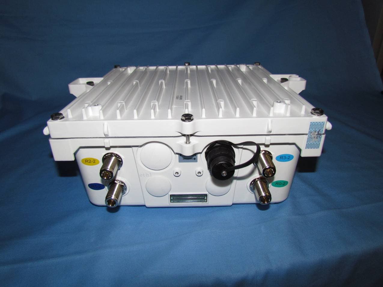
Click to zoom
Application Details
- Equipment Class
- DTS - Digital Transmission System
- Date of Grant
- Apr 10, 2011
- Application Purpose
- Original Equipment
- Date of Application
- Apr 10, 2011
- Equipment Note
- Aruba Networks MSR4000 Access Point
- Frequency Range
- 5755.00000000 - 5815.00000000
- Country
- United States
Documents & Files
Document Text
Text extracted from the exhibit documents filed with the FCC. Open a document above to read the original.
Users Manual
0510871-01 Aruba Networks MSR4000 Installation Guide MSR4000 Installation Guide 1 Copyright 2005-2011 by Aruba Networks, USA. All rights reserved. Statement of Conditions In the interest of improving internal design, operation function, and/or reliability, Aruba Networks reserves the right to make changes to products described in this document without notice. Aruba Networks does not assume any liability that may occur due to the use or application of the product(s) described herein. DISCLAIMER: LIMITATION OF LIABILITY 1.Before installation, it’s strongly recommended and requested that users pay particular attention to the safety warnings in the sequentially detailed operation procedures within the manual. If there’s any uncertainty or incapability of solving problems, contact the company’s customer support center. Please DO NOT incur any risk or try to verify situations by yourself. Otherwise, any consequence caused by the attempt shall be completely due to the user himself. 2.Please periodically check whether the installed MSR4000 is damaged, worn-out or poses any danger. Any actual proof, sign or phenomenon of the afore-mentioned situations should be brought to the attention of the company at point of sale. Please DO NOT attempt to repair the product or replace any component. Otherwise, for any consequence arising out of or relating to the users’ attempt repair the product, including but not limited to damages, disuse, short circuit, fire, bodily injury, etc., the company shall not be liable. 3. Users shall purchase or use the company’s MSR4000 voluntarily. Users shall understand on their own initiative and abide voluntarily by policies, regulations or laws of their respective nation or local territories. The consequence arising out of or relating to any violation of the local laws or regulations by the user, shall be solely imputed to the user himself, and the company shall not be liable. 4. The company disclaims any and all warranties and guarantees, express, implied or otherwise, arising, with respect to the MSR4000 products or services, including but not limited to the warranty of MSR4000 Installation Guide 2 merchandisability, the warranty of fitness for a particular purpose, and any warranty of non- infringement of the intellectual property rights of any third party. Liability of the company for loss is limited to the total amount paid to the company by the customer during the previous calendar year. The company will have no obligation or liability, whether arising in contract (including Warranty), tort (including active, passive or imputed negligence, strict liability or product liability) or otherwise for any special, incidental, consequential or indirect damages including but not limited to loss of use, loss of data, business interruption, loss of revenue, loss of business or other financial loss arising out of or in connection with any of the products or other goods or services furnished by the company under this manual, even if advised of the possibility of such damages. 5.It shall never be understood that the manual expresses or implies to any customer or any third party authorize or transfer any rights. The company reserves fully the final interpretation of the MSR4000 and this manual. Safety Warnings The MSR4000 must be installed by trained professional installation technicians. All warnings below must be read and understood before installation. General Safety Warnings You can be killed or injured if performing antenna installation near electrical power lines. Carefully read and follow all instructions in this guide. Please be sure there are no high voltage and electronic fields nearby. Working Aloft Warning When working on tower or roof, individuals must wear safety belts. Tools must be tied to the individual using them. Workers below must wear safety helmets. Lightning Activity Warning MSR4000 Installation Guide 3 Make sure not to connect or disconnect cables during periods of lightning activity. A surge protective device should be installed to prevent potential damage from very high surges, for instance, the peak surges caused by lightning. Explosive Device Proximity Warning Do not operate wireless network devices close to explosive merchandise or in explosive environments if devices are not certified for operation in such an environment, for example, in the vicinity of a gas station. Antenna Placement Warning Do not install any antenna near overhead power lines or other electric light, or where the antenna can come into contact with such circuits. Antenna Selection Warning Please use DC grounding antenna with lightning protection to prevent surge and static electricity. Grounding Warning Please always remember to protect your MSR4000 system by installation of grounding lines. The ground connection must be complete before connecting power to the MSR4000 enclosure. The requirement of grounding is to make sure the resistance must be less than 5 ohm between the ground termination point to grounding tier. Power Installation Warning MSR4000 Installation Guide 4 The installation of the power switch must be performed by a trained professional technician. The power switch is not supplied with the MSR4000. The power cord must be assembled by a professional installer, and the final assembly must comply with related requirements. Solar Irradiation and High Temperature Protection Pay attention to level of sunlight, which can increase the working temperature of MSR4000 to higher than specifications allow. A solar shield is provided in the Aruba standard package and should be installed to protect any outdoor MSR4000. The Aruba Warrantee policy does not cover those outdoor products for which Solar shields are not installed. Please contact Aruba technical support engineers for detailed information. RF Device Protection Before powering up the MSR4000, the RF port must be connected to an antenna or a valid load (not included in the standard accessories for MSR4000). Otherwise, the RF mo…
Text truncated - open the document above for the full version.
Users Manual
Professional installation Guide Product/s covered in this guide: Model: MSR4K43N0-XX is part of the Aruba’s MSR4000 family, implementing quad radio cards each 2x2 MIMO supporting IEEE 802.11 a/b/g/n/j operation. IMPORTANAT - Visit Aruba Support web page for the latest information and documentation related to this product. IMPORTANAT – Please read this document before installing and using your product. This device must be installed and used in strict accordance with the manufacturer's instructions. Only approved by the manufacturer power adapters must be used. For replacement, contact your supplier or distributor. Installation of this product must comply with local regulations and codes. When this product is used with external antenna/s, please refer to the installation documentation provided for the antenna/s. Changes or modifications to the device not approved by the manufacturer of the product could void the user’s authority to operate the equipment and will void the warranty of the product. No user serviceable parts; all repairs and service must be handled by a qualified service center. All products using external antennas must be professionally installed, and the transmit power of the system must be adjusted by the professional installer/s to ensure that the system’s EIRP is in compliance with the limit specified by the regulatory authority of the country of deployment. During deployment of the system and its initial setup, professional installer must ensure that the allowed EIRP limit is not exceeded (in the Country of exploitation of this equipment). To achieve this professional installer must use approved and recommended by the Manufacturer antennas, 1. ANT-2x2-2714 2.4G,14DB,70DEG SECTR,2x2,N-TYPE 2. ANT-2x2-5614U 5.5G-5.8G,14DB,60DEG SECTR,2x2,N-TYPE 3. AP-ANT-80D 2.4GHz Outdoor 8dBi Omni Antenna 4. AP-ANT-86 4.9G-5.9G Outdoor 10dBi Omni Antenna and enter Antenna gain in the software using to setup and mange the product. In additional attenuation between the device and antenna may have to be measured or calculated. The following formula can be used to calculate from EIRP limit related RF power based on selected antennas (antenna gain) and feeder (Coaxial Cable loss): EIRP = Tx RF Power (dBm) +G A (dB) - F L (dB); EIRP –> limit specific for each Country of deployment Tx RF Power –> RF power measured at RF connector of the unit G A –> Antenna gain F L -> Feeder loss (including the connectors’ loss) Antenna Types and Maximum Antenna Gains Frequency Band Type Gain (dBi) 2.4 GHz Dipole/Omni 9 Directional14 5 GHz Dipole/Omni 11 Directional14 Note: Antenna information provided above reflect approved antennas for initial release of the device. For full list of antennas approved/recommended by the Manufacture please visit the Aruba Networks Inc. web site.
Cover Letter(s)
Federal Communications Commission Equipment Authorization Branch 7435 Oakland Mills Road Columbia, MD 21046 Letter of Authorization Company: Aruba Networks, Inc. FCC ID:Q9DMSR4000 We authorize MiCOM Labs, 440 Boulder Court, Suite 200, Pleasanton, CA 94566, USA, to act on our behalf on all matters concerning the above named equipment. This shall include the following: - Testing - Approval applications and procedures - Payment of approval fees We declare that MiCOM Labs, 440 Boulder Court, Suite 200, Pleasanton, CA 94566, USA, is allowed to forward all information related to the approval project to the applied notified body and to the notification entities and to discuss any issues concerning the approval application. Any and all acts carried out by MiCOM Labs on our behalf shall have the same effect as acts of our own. Sincerely, Signature Ivaylo Tankov Compliance Manager Aruba Networks, Inc. 1344 Crossman Ave., Sunnyvale, CA 94089 Tel: (408) 227 4500 Email: [email protected]
Cover Letter(s)
Federal Communications Commission Equipment Authorization Branch 7435 Oakland Mills Road Columbia, MD 21046 Letter of Authorization March 25, 2011 Company: Aruba Networks, Inc. FCC ID:Q9DMSR4000 Gentlemen, In accordance with 0.459 of CFR 47, Aruba Networks, Inc hereby requests confidentiality of the following documents for the subject application. - Schematics - Block Diagram - Theory of Operation - Bill of Materials These documents contain detailed system and equipment description and related information about the product which Aruba Networks considers to be proprietary, confidential and a custom design and otherwise would not release to the general public. Since the design is a basis from which future technological products will evolve, Aruba Networks considers that this information would be of benefit to its competitors and that the disclosure of the information in these documents would give competitors an unfair advantage in the market. Sincerely, Signature Ivaylo Tankov Compliance Manager Aruba Networks, Inc. 1344 Crossman Ave., Sunnyvale, CA 94089 Tel: (408) 227 4500 Email: [email protected]
External Photos
the wireless lab 5 April 2011 External Photographs Aruba Networks, Inc. MSR4000 Wireless Access Point MiCOM Labs, 440 Boulder Court, Suite 200, Pleasanton, CA 94566 Tel: +1 (925) 462-0304, Fax: +1 (925) 462-0306, Web: www.micomlabs.com the wireless lab Page 2 of 2
ID Label/Location Info
the wireless lab Label artwork MiCOM Labs, 440 Boulder Court, Suite 200, Pleasanton, CA 94566 Tel: +1 (925) 462-0304, Fax: +1 (925) 462-0306, Web: www.micomlabs.com the wireless lab Label Location Page 2 of 2
Internal Photos
the wireless lab 8 April 2011 Internal Photographs Aruba Networks, Inc. MSR4000 Main Assy front MiCOM Labs, 440 Boulder Court, Suite 200, Pleasanton, CA 94566 Tel: +1 (925) 462-0304, Fax: +1 (925) 462-0306, Web: www.micomlabs.com the wireless lab Front Main Assy Page 2 of 10 the wireless lab Back Main Assy Page 3 of 10 the wireless lab Top RF Card Back RF card Page 4 of 10 the wireless lab Top Main RF Holder Back Main RF Holder Page 5 of 10 the wireless lab Front Temperature Sensor Back Temperature Sensor Page 6 of 10 the wireless lab Top Bridge Board Back Bridge Board Page 7 of 10 the wireless lab LED Front LED Back Page 8 of 10 the wireless lab Front Back Plane Back, Back Plane Page 9 of 10 the wireless lab POE Front POE Back Page 10 of 10
Test Report
COVER PAGE Test of MSR4000 802.11a/b/g/n Access Point To: FCC 47 CFR Part 15.247 & IC RSS-210 Test Report Serial No.: ARUB65-U1 Rev A TITLE PAGE TEST REPORT FROM Test of MSR4000 802.11a/b/g/n Access Point to To FCC 47 CFR Part 15.247 & IC RSS-210 Test Report Serial No.: ARUB65-U1 Rev A Note: this report contains data with regard to the 2400 to 2483.5 MHz and 5725 to 5850 MHz operational modes of the Aruba Networks MSR4000 Wireless Access Point. This report supersedes: NONE Applicant: Aruba Networks, Inc 1344 Crossman Avenue Sunnyvale California 94089, USA Product Function: Wireless Access Point Copy No: pdf Issue Date: 4th April 2011 MiCOM Labs is an ISO 17025 Accredited Testing Laboratory This Test Report is Issued Under the Authority of; MiCOM Labs, Inc. 440 Boulder Court, Suite 200 Pleasanton, CA 94566 USA Phone: +1 (925) 462-0 304 Fax: +1 (925) 462-0306 TEST CERTIFICATE #2381.01 www.micomlabs.com This test report may be reproduced in full only. The document may only be updated by MiCOM Labs personnel. Any changes will be noted in the Document History section of the report. Title: MSR4000 802.11a/b/g/n Access Point To: Serial #: Issue Date: Page: FCC 47 CF R Part 15.247 & IC RSS-210 ARUB65-U1 Rev A 4th April 2011 3 of 207 This test report may be reproduced in full only. The document may only be updated by MiCOM Labs personnel. Any changes will be noted in the Document History section of the report. MiCOM Labs, 440 Boulder Court, Suite 200, Pleasanton, CA 94566 USA, Phone: 925.462.0304, Fax: 925.462.0306, www.micomlabs.com This page has been left intentionally blank Title: MSR4000 802.11a/b/g/n Access Point To: Serial #: Issue Date: Page: FCC 47 CF R Part 15.247 & IC RSS-210 ARUB65-U1 Rev A 4th April 2011 4 of 207 This test report may be reproduced in full only. The document may only be updated by MiCOM Labs p ersonnel. Any changes will be noted in the Document History section of the report. MiCOM Labs, 440 Boulder Court, Suite 200, Pleasanton, CA 94566 USA, Phone: 925.462.0304, Fax: 925.462.0306, www.micomlabs.com TABLE OF CONTENTS ACCREDITATION, LISTINGS & RECOGNITION ............................................................ 5 TESTING ACCREDITATION ............................................................................................ 5 RECOGNITION ................................................................................................................. 6 PRODUCT CERTIFICATION ............................................................................................ 7 1. TEST RESULT CERTIFICATE ................................................................................... 9 2. REFERENCES AND MEASUREMENT UNCERTAINTY ........................................ 10 2.1. Normative References ............................................................................................. 10 2.2. Test and Uncertainty Procedures ............................................................................ 11 3. PRODUCT DETAILS AND TEST CONFIGURATIONS .......................................... 12 3.1. Technical Details ..................................................................................................... 12 3.2. Scope of Test Program ............................................................................................ 13 3.3. Equipment Model(s) and Serial Number(s) ............................................................. 18 3.4. Antenna Details ....................................................................................................... 18 3.5. Cabling and I/O Ports .............................................................................................. 18 3.6. Test Configurations.................................................................................................. 19 3.7. Equipment Modifications.......................................................................................... 21 3.8. Deviations from the Test Standard .......................................................................... 25 3.9. Subcontracted Testing or Third Party Data ............................................................. 25 4. TEST SUMMARY ...................................................................................................... 26 5. TEST RESULTS ........................................................................................................ 28 5.1. Device Characteristics ............................................................................................. 28 5.1.1. 6 dB and 99 % Bandwidth ........................................................................28 5.1.2. Peak Output Power ..................................................................................58 5.1.3. Peak Power Spectral Density...................................................................64 5.1.4. Maximum Permissible Exposure ..............................................................94 5.1.5. Conducted Spurious Emissions ...............................................................95 5.1.6. Radiated Emissions ...............................................................................132 5.1.7. AC Wireline Conducted Emissions (150 kHz – 30 MHz)........................200 6. PHOTOGRAPHS..................................................................................................... 203 6.1. Conducted Test Setup ........................................................................................... 203 6.2. Radiated Test Setup (0.03 – 1 GHz) ..................................................................... 204 6.3. Radiated Test Setup (above 1 GHz)...................................................................... 205 7. TEST EQUIPMENT DETAILS................................................................................. 206 Title: MSR4000 802.11a/b/g/n Access Point To: Serial #: Issue Date: Page: FCC 47 CF R Part 15.247 & IC RSS-210 ARUB65-U1 Rev A 4th April 2011 5 of 207 This test report may be repr…
Text truncated - open the document above for the full version.
Test Setup Photos
the wireless lab 5 April 2011 Test Set Up Photographs Aruba Networks, Inc. MSR4000 Conducted Test Setup MiCOM Labs, 440 Boulder Court, Suite 200, Pleasanton, CA 94566 Tel: +1 (925) 462-0304, Fax: +1 (925) 462-0306, Web: www.micomlabs.com the wireless lab Radiated Test Setup (0.03 – 1 GHz) Page 2 of 3 the wireless lab Radiated Test Setup (above 1 GHz) Page 3 of 3
Contact Information
Applicant
Mark Hill(Principal Engineer)
Test Firm
Micom LabsGordon Hurst
Technical Specifications
| # | Rule Parts | Frequency Range | Power Output | Emission | Tolerance |
|---|---|---|---|---|---|
| 4 | 15C | 5.75 GHz - 5.82 GHz | 187.00 mW | 36M8D1D | 20 ppm |
Other Applications from Hewlett Packard Enterprise Company
Q9DAPINH721
Jul 17, 2026Access Point
Equipment Class
6ID - 15E 6 GHz Low Power Indoor Access PointQ9DASIN0307
Dec 22, 2025HPE Aruba User Experience Sensor
Equipment Class
DTS - Digital Transmission SystemQ9DASIN0308
Nov 23, 2025HPE Aruba User Experience Sensor
Equipment Class
DTS - Digital Transmission SystemQ9DAPEX0764
Nov 20, 2025ACCESS POINT
Equipment Class
DTS - Digital Transmission SystemQ9DAPIN0763
Sep 29, 2025ACCESS POINT
Equipment Class
NII - Unlicensed National Information Infrastructure TX