Q9DMSR4000ACWireless Mesh Router
Hewlett Packard Enterprise Company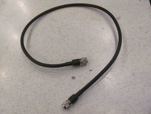
Click to zoom
Application Details
- Equipment Class
- TNB - Licensed Non-Broadcast Station Transmitter
- Date of Grant
- Feb 23, 2012
- Application Purpose
- Original Equipment
- Date of Application
- Feb 22, 2012
- Equipment Note
- Wireless Mesh Router
- Frequency Range
- 4980.00000000 - 4980.00000000
- Country
- United States
Documents & Files
Document Text
Text extracted from the exhibit documents filed with the FCC. Open a document above to read the original.
Users Manual
0510871-04 Aruba Networks MSR4000 Installation Guide MSR4000 Installation Guide 1 Copyright 2005-2012 by Aruba Networks, USA. All rights reserved. Statement of Conditions In the interest of improving internal design, operation function, and/or reliability, Aruba Networks reserves the right to make changes to products described in this document without notice. Aruba Networks does not assume any liability that may occur due to the use or application of the product(s) described herein. DISCLAIMER: LIMITATION OF LIABILITY 1.Before installation, it’s strongly recommended and requested that users pay particular attention to the safety warnings in the sequentially detailed operation procedures within the manual. If there’s any uncertainty or incapability of solving problems, contact the company’s customer support center. Please DO NOT incur any risk or try to verify situations by yourself. Otherwise, any consequence caused by the attempt shall be completely due to the user himself. 2.Please periodically check whether the installed MSR4000 is damaged, worn-out or poses any danger. Any actual proof, sign or phenomenon of the afore-mentioned situations should be brought to the attention of the company at point of sale. Please DO NOT attempt to repair the product or replace any component. Otherwise, for any consequence arising out of or relating to the users’ attempt repair the product, including but not limited to damages, disuse, short circuit, fire, bodily injury, etc., the company shall not be liable. 3. Users shall purchase or use the company’s MSR4000 voluntarily. Users shall understand on their own initiative and abide voluntarily by policies, regulations or laws of their respective nation or local territories. The consequence arising out of or relating to any violation of the local laws or regulations by the user, shall be solely imputed to the user himself, and the company shall not be liable. 2 MSR4000 Installation Guide 4. The company disclaims any and all warranties and guarantees, express, implied or otherwise, arising, with respect to the MSR4000 products or services, including but not limited to the warranty of merchandisability, the warranty of fitness for a particular purpose, and any warranty of non-infringement of the intellectual property rights of any third party. Liability of the company for loss is limited to the total amount paid to the company by the customer during the previous calendar year. The company will have no obligation or liability, whether arising in contract (including Warranty), tort (including active, passive or imputed negligence, strict liability or product liability) or otherwise for any special, incidental, consequential or indirect damages including but not limited to loss of use, loss of data, business interruption, loss of revenue, loss of business or other financial loss arising out of or in connection with any of the products or other goods or services furnished by the company under this manual, even if advised of the possibility of such damages. 5.It shall never be understood that the manual expresses or implies to any customer or any third party authorize or transfer any rights. The company reserves fully the final interpretation of the MSR4000 and this manual. Safety Warnings The MSR4000 must be installed by trained professional installation technicians. All warnings below must be read and understood before installation. General Safety Warnings You can be killed or injured if performing antenna installation near electrical power lines. Carefully read and follow all instructions in this guide. Please be sure there are no high voltage and electronic fields nearby. Working Aloft Warning When working on tower or roof, individuals must wear safety belts. Tools MSR4000 Installation Guide 3 must be tied to the individual using them. Workers below must wear safety helmets. Lightning Activity Warning Make sure not to connect or disconnect cables during periods of lightning activity. A surge protective device should be installed to prevent potential damage from very high surges, for instance, the peak surges caused by lightning. Explosive Device Proximity Warning Do not operate wireless network devices close to explosive merchandise or in explosive environments if devices are not certified for operation in such an environment, for example, in the vicinity of a gas station. Antenna Placement Warning Do not install any antenna near overhead power lines or other electric light, or where the antenna can come into contact with such circuits. Antenna Selection Warning Please use DC grounding antenna with lightning protection to prevent surge and static electricity. Grounding Warning Please always remember to protect your MSR4000 system by installation of 4 MSR4000 Installation Guide grounding lines. The ground connection must be complete before connecting power to the MSR4000 enclosure. The requirement of grounding is to make sure the resistance must be less than 5 ohm between the ground termination point to grounding tier. Power Installation Warning The installation of the power switch must be performed by a trained professional technician. The power switch is not supplied with the MSR4000. The power cord must be assembled by a professional installer, and the final assembly must comply with related requirements. Solar Irradiation and High Temperature Protection Pay attention to level of sunlight, which can increase the working temperature of MSR4000 to higher than specifications allow. A solar shield is provided in the Aruba standard package and should be installed to protect any outdoor MSR4000. The Aruba Warrantee policy does not cover those outdoor products for which Solar shields are not installed. Please contact Aruba technical support engineers for detailed information. RF Device Protection Before powering up the MSR4000, the RF port must be connected to an antenna or a valid load (not included in the standard accessories for MSR4000). Otherwise, the RF mod…
Text truncated - open the document above for the full version.
Users Manual
Professional installation Guide Product/s covered in this guide: Model: MSR4K43N3-XXX is part of the Aruba’s MSR4000 family, implementing quad radio cards each 2x2 MIMO supporting IEEE 802.11 a/b/g/n/j operation. IMPORTANAT - Visit Aruba Support web page for the latest information and documentation related to this product. IMPORTANAT – Please read this document before installing and using your product. This device must be installed and used in strict accordance with the manufacturer's instructions. Only approved by the manufacturer power adapters must be used. For replacement, contact your supplier or distributor. Installation of this product must comply with local regulations and codes. When this product is used with external antenna/s, please refer to the installation documentation provided for the antenna/s. Changes or modifications to the device not approved by the manufacturer of the product could void the user’s authority to operate the equipment and will void the warranty of the product. No user serviceable parts; all repairs and service must be handled by a qualified service center. All products using external antennas must be professionally installed, and the transmit power of the system must be adjusted by the professional installer/s to ensure that the system’s EIRP is in compliance with the limit specified by the regulatory authority of the country of deployment. During deployment of the system and its initial setup, professional installer must ensure that the allowed EIRP limit is not exceeded (in the Country of exploitation of this equipment). To achieve this professional installer must use approved and recommended by the Manufacturer antennas, and enter Antenna gain in the software using to setup and mange the product. In additional attenuation between the device and antenna may have to be measured or calculated. The following formula can be used to calculate from EIRP limit related RF power based on selected antennas (antenna gain) and feeder (Coaxial Cable loss): EIRP = Tx RF Power (dBm) +G A (dB) - F L (dB); EIRP –> limit specific for each Country of deployment Tx RF Power –> RF power measured at RF connector of the unit G A –> Antenna gain F L -> Feeder loss (including the connectors’ loss) Note: Antenna information provided above reflect approved antennas for initial release of the device. For full list of antennas approved/recommended by the Manufacture please visit the Aruba Networks Inc. web site. Ap-ANT-80D (8dBi for 2.4GHz) Ap-ANT-85 (15dBi for 2.4GHz) Ap-ANT-2*2-5614 (14dBi for 5.8GHz) Ap-ANT-86 (9dBi for 5.8GHz)
Cover Letter(s)
AUTHORIZATION LETTER FCC ID :Q9DMSR4000AC Data: February 6 ,2012 TO whom it may concern: We ,the undersigned, hereby authorize intertek Shanghai of China to act on our behalf, as our agent, in the following matters related to the FCC approval of our products: report submittal, related correspondence , the singing of all documents relating to these matters, and any carried out by Intertek Shanghai within the scope of this authorization shall have the same effects as our own. This authorization shall expire 6 months from original data. If you have any questions regarding the authorization, please don’t hesitate to contact me. Thank you Sincerely, Ivaylo Tankov Compliance Manager Aruba Networks,Inc. Tel :+1 408 754 3035 Email: [email protected]
Cover Letter(s)
CONFIDENTIALITY REQUEST FCC ID : Q9DMSR4000AC Pursuant to Sections 0.457 and 0.459 of the Federal Communications Commission’s Rules ,the Applicant hereby requests confident treatment of information accompanying this Applicant as outlined below: 1) Schematic diagram 2) Block diagram 3) Operational description 4) BOM 5) Tune-up procedure The above material contains trade secrets or technical data which Aruba Networks,Inc. deems to be proprietary. Therefore this information would customarily be guarded from competitors and cannot be accessible to the general public. Thank you Sincerely, Ivaylo Tankov Compliance Manager Aruba Networks,Inc. Tel: +1 408 754 3035 Email: [email protected]
External Photos
FCC ID: Q9DMSR4000AC IC: 4675A-MSR4000AC Page 1 of 4 External Picture FCC ID: Q9DMSR4000AC IC: 4675A-MSR4000AC Page 2 of 4 FCC ID: Q9DMSR4000AC IC: 4675A-MSR4000AC Page 3 of 4 FCC ID: Q9DMSR4000AC IC: 4675A-MSR4000AC Page 4 of 4 RF cable between antenna and RF connector
ID Label/Location Info
4011089 401108901 01 01 MSR4K43N3 4675A-MSR4000AC Q9DMSR4000AC MODEL: FCC ID: IC: SPEC: IP66 100-240V~0.75A 50/60 Hz 4011089 401108901 01 01 4675A-MSR4000AC Q9DMSR4000AC MODEL: FCC ID: IC: SPEC: IP66 100-240V~0.75A 50/60 Hz MSR4K43N3-US Label Position
Internal Photos
FCC ID: Q9DMSR4000AC IC: 4675A-MSR4000AC Page 1 of 22 Internal Picture FCC ID: Q9DMSR4000AC IC: 4675A-MSR4000AC Page 2 of 22 Overview for inside EUT FCC ID: Q9DMSR4000AC IC: 4675A-MSR4000AC Page 3 of 22 Spiderman FCC ID: Q9DMSR4000AC IC: 4675A-MSR4000AC Page 4 of 22 FCC ID: Q9DMSR4000AC IC: 4675A-MSR4000AC Page 5 of 22 FCC ID: Q9DMSR4000AC IC: 4675A-MSR4000AC Page 6 of 22 BlutemPSE . FCC ID: Q9DMSR4000AC IC: 4675A-MSR4000AC Page 7 of 22 Main board + TRIBRI FCC ID: Q9DMSR4000AC IC: 4675A-MSR4000AC Page 8 of 22 TRIBRI FCC ID: Q9DMSR4000AC IC: 4675A-MSR4000AC Page 9 of 22 FCC ID: Q9DMSR4000AC IC: 4675A-MSR4000AC Page 10 of 22 FCC ID: Q9DMSR4000AC IC: 4675A-MSR4000AC Page 11 of 22 Main board FCC ID: Q9DMSR4000AC IC: 4675A-MSR4000AC Page 12 of 22 LED board FCC ID: Q9DMSR4000AC IC: 4675A-MSR4000AC Page 13 of 22 Tribac FCC ID: Q9DMSR4000AC IC: 4675A-MSR4000AC Page 14 of 22 FCC ID: Q9DMSR4000AC IC: 4675A-MSR4000AC Page 15 of 22 TriEXP FCC ID: Q9DMSR4000AC IC: 4675A-MSR4000AC Page 16 of 22 FCC ID: Q9DMSR4000AC IC: 4675A-MSR4000AC Page 17 of 22 FCC ID: Q9DMSR4000AC IC: 4675A-MSR4000AC Page 18 of 22 FCC ID: Q9DMSR4000AC IC: 4675A-MSR4000AC Page 19 of 22 Ttiexp board + RF cards FCC ID: Q9DMSR4000AC IC: 4675A-MSR4000AC Page 20 of 22 RF cards FCC ID: Q9DMSR4000AC IC: 4675A-MSR4000AC Page 21 of 22 FCC ID: Q9DMSR4000AC IC: 4675A-MSR4000AC Page 22 of 22
Operational Description
Outdoor MIMO Antenna ANT-2x2-5614Aruba Data Sheet ArubA OutdOOr MIMO AntennA Ant-2x2-5614 ANT-2x2-5614 is a two-element 60-degree sector antenna for use in 802.11n MIMO mesh link applications. The antenna integrates two differently polarized elements, and provides coverage of the 4.9 - 5.875 GHz frequency band in a single antenna radome. Due to regulatory restrictions, this antenna is not certified for use in the North American markets. The 5614U or 5614L should be used instead. FreQuenCY / MAx GAIn • 4.9 - 5.875 GHz (14 dBi) POlArIzAtIOn • Dual slant, +/- 45 degrees beAMwIdth • E-plane: 14 degrees • H-plane: 60 degrees IMPedAnCe • 50 ohms MAxIMuM InPut POwer • 20 watts VSwr (MInIMuM PerFOrMAnCe) • < 1.8:1 AntennA PAtternS dIMenSIOnS • 270 x 103 x 35 mm (10.63” x 4.06” x 1.38”) • Shipping: 360 x 125 x 50 mm (14.17” x 4.92” x 1.97”) weIGht • 650 g (1.43 ib) COnneCtOr • N-type female (2x) • Note: RF cables not included. OPerAtInG / StOrAGe teMP. • -40° to +70° C InStAllAtIOn hArdwAre • Kit for wall and pole mounting included. Elevation (vertical) angle is adjustable. E-plane (side view) – 5.5 GHzH-plane (top view) – 5.5 GHz Outdoor MIMO Antenna ANT-2x2-5614Aruba Data Sheet © 2011 Aruba Networks, Inc. Aruba Networks’ trademarks include AirWave®, Aruba Networks®, Aruba Wireless Networks®, the registered Aruba the Mobile Edge Company logo, Aruba Mobility Management System®, Mobile Edge Architecture®, People Move. Networks Must Follow®, RFProtect®, and Green Island®. All rights reserved. All other trademarks are the property of their respective owners. DS_ANT-2x2-5614_110920 1344 Crossman Avenue. Sunnyvale, CA 94089 1-866-55-ARUBA | Tel. +1 408.227.4500 | Fax. +1 408.227.4550 | [email protected] www.arubanetworks.com
Operational Description
0 350 340 330 320 310 300 290 280 270 260 250 240 230 220 210 200 190 180 170 160 150 140 130 120 110 100 90 80 70 60 50 40 30 20 10 -30-20-10 dB 0 350 340 330 320 310 300 290 280 270 260 250 240 230 220 210 200 190 180 170 160 150 140 130 120 110 100 90 80 70 60 50 40 30 20 10 -30-20-10 dB Frequency / Gain • 5.150 GHz - 5.875 GHz / 9.0 dBi POLariZaTiOn • Omni-directional, Linear Vertical BeaMWiDTH • E-Plane 8 degrees iMPeDance • 50 ohms MaXiMuM in PuT POWer • 10 watts VSWr (MiniMuM PerFOrMance) • 2.0:1 DiMenSiOnS (incHeS/ cenTiMeTerS) • 19.5” (49.53 cm) x 1” (2.54 cm) HOuSin G • UV-stable Polycarbonate FLy caBLe L enGTH / cOnnecTOr • 36” / N-Type Male OPeraTin G TeMPeraTure • -30° C to +65° C / -22° F to +149° F Win D SPeeD SurViVaL (MPH/KPH) • N/A in STaLLaTiOn H arDWare • 1” to 2 1/8” mast mounting kit included DATA SheeT Aruba AP-ANT-86 Outdoor Antenna aruBa aP-anT-86 OuTDOOr 5 GHZ OMni-DirecTiOnaL anTenna The AP-ANT-86 is a high-gain omni-directional outdoor cylindrical antenna, de- signed for general purpose outdoor coverage over a wide area in the 5 GHz band for applications such as outdoor Mesh topologies, storage, shipping or rail yards, parks and warehouses. The AP-ANT-86 is enclosed in a weather resistant UV-stable 19.5” X 1” housing that can be mast or pole mounted using its supplied mount kit. ElEvation PlanE - 5150MHz azi MutH PlanE - 5150MHz © 2007 Aruba Networks, Inc. All rights reserved. Aruba Networks is a trademark of Aruba Networks, Inc. All other trademarks or registered trademarks are the property of their respective holders. Specifications are subject to change without notice. DS_ANT86_US_070907 www.arubanetworks.com 1322 Crossman Avenue. Sunnyvale, CA 94089 | Tel. +1 408.227.4500 | Fax. +1 408.227.4550 0 350 340 330 320 310 300 290 280 270 260 250 240 230 220 210 200 190 180 170 160 150 140 130 120 110 100 90 80 70 60 50 40 30 20 10 -30-20-10 dB 0 350 340 330 320 310 300 290 280 270 260 250 240 230 220 210 200 190 180 170 160 150 140 130 120 110 100 90 80 70 60 50 40 30 20 10 -30-20-10 dB 0 350 340 330 320 310 300 290 280 270 260 250 240 230 220 210 200 190 180 170 160 150 140 130 120 110 100 90 80 70 60 50 40 30 20 10 -30-20-10 dB 0 350 340 330 320 310 300 290 280 270 260 250 240 230 220 210 200 190 180 170 160 150 140 130 120 110 100 90 80 70 60 50 40 30 20 10 -30-20-10 dB ElEvation PlanE - 5500MHz ElEvation PlanE - 5870MHz azi MutH PlanE - 5500MHz azi MutH PlanE - 5870MHz aruBa aP-anT-86 OuTDOOr anTenna
RF Exposure Info
FCC ID: Q9DMSR4000AC IC: 4675A-MSR4000AC Page 1 of 2 Statement of compliance to Maximum Permissible Exposure (MPE) Applicant : Aruba Networks, Inc. 1322 Crossman Ave., Sunnyvale CA 94089 USA Type/Model : MSR4K43N3XXX (Where X=A to Z, Blank or Symbol for marketing purpose) According to §2.1091, §2.1093 and §1.1307(b), systems operating under the provisions of this section shall be operated in a manner that ensures that the public is not exposed to radio frequency energy level in excess of the Commission’s guidelines. The S = PG / (4πR²) Where S = power density in mW/cm² P = transmit power in mW G = numeric gain of transmit antenna R = distance (cm) As we can see from the test reports SH12020032-001 and SH12020032-002: 1) If the antennas Ap-ANT-80D with gain of 8dBi & Ap-ANT-86 with gain of 9dBi are applied, the maximum P of single RF card = 25.89dBm = 388.150mW If the four RF cards work simultaneously, the total conducted power=388.150*4= 1552.600mW G = 9dBi = 7.903 R is chosen to be 40cm, S = PG / (4πR²) =1552.600 * 7.903 / (4 * 3.14 * 40 * 40) = 0.61mW/cm² 2) If the antennas Ap-ANT-2*2-5614 with gain of 14dBi & Ap-ANT-85 with gain of 15dBi are applied, the maximum P of single RF card = 20.96dBm = 124.738mW If the four RF cards work simultaneously, the total conducted power =124.738*4= 498.952mW G = 15dBi = 31.623 R is chosen to be 40m, S = PG / (4πR²) = 498.952 * 31.623 / (4 * 3.14 * 40 * 40) = 0.79mW/cm² This level is below the 1 mW/cm² MPE for General Population / Uncontrolled Exposure as stated in OET BULLETIN 65 Edition 97-01. Date of issue: Sep 16, 2012 Prepared by: Reviewed by: Wakeyou Wang (Project Engineer) Daniel Zhao (Reviewer) FCC ID: Q9DMSR4000AC IC: 4675A-MSR4000AC Page 2 of 2 Appendix I Definition below must be outlined in the User Manual: To satisfy FCC RF exposure requirements, a separation distance of 40 cm or more should be maintained between the antenna of this device and persons during device operation. To ensure compliance, operations at closer than this distance is not recommended.
Test Report
FCC ID: Q9DMSR4000AC IC: 4675A-MSR4000AC Page 1 of 66 EMC TEST REPORT for Licensed Device No. SH12020032-001 Applicant : Aruba Networks, Inc. 1322 Crossman Ave., Sunnyvale CA 94089 USA Manufacturer : Aruba Networks, Inc. 1322 Crossman Ave., Sunnyvale CA 94089 USA Product Name : Wireless Mesh Router Type/Model : MSR4K43N3XXX (Where X=A to Z, Blank or Symbol for marketing purpose) SUMMARY The equipment complies with the requirements according to the following standard(s): 47CFR Part 90 (2010): Private Land Mobile Radio Service TIA/EIA-603-C (2004): Land Mobile FM or PM – Communications Equipment – Measurement and performance Standards RSS-Gen Issue 3 (December 2010): General Requirements and Information for the Certification of Radiocommunication Equipment RSS-111 Issue 4 (January 2012): Broadband Public Safety Equipment Operating in the Band 4940-4990 MHz Date of issue: Feb 16, 2012 Prepared by: Reviewed by: Wakeyou Wang (Project Engineer) Daniel Zhao (Reviewer) FCC ID: Q9DMSR4000AC IC: 4675A-MSR4000AC Page 2 of 66 Description of Test Facility Name: Intertek Testing Services Ltd. Shanghai ETL Semko Address: Building No.86, 1198 Qinzhou Road(North), Shanghai 200233, P.R. China FCC Registration Number: 236597 IC Assigned Code: 2042B-1 Name of contact: Steve Li Tel: +86 21 64956565 ext. 214 Fax: +86 21 54262335 ext. 214 FCC ID: Q9DMSR4000AC IC: 4675A-MSR4000AC Page 3 of 66 Content SUMMARY .......................................................................................................................................................... 1 DESCRIPTION OF TEST FACILITY ......................................................................................................................... 2 1. GENERAL INFORMATION ............................................................................................................................ 5 1.1 Applicant Information ..................................................................................................... 5 1.2 Identification of the EUT ................................................................................................ 5 1.3 Technical specification ................................................................................................... 6 1.4 Mode of operation during the test / Test peripherals used .............................................. 7 2. TEST SPECIFICATION .................................................................................................................................. 8 2.1 Instrument list ................................................................................................................. 8 2.2 Test Standard .................................................................................................................. 8 2.4 RF cards VS Power ....................................................................................................... 10 2.5 Data rate VS power ....................................................................................................... 11 3. TRANSMITTER CARRIER OUTPUT POWER ............................................................................................... 12 3.1 Limit .............................................................................................................................. 12 3.2 Test Configuration ........................................................................................................ 12 3.3 Test Procedure and test setup ........................................................................................ 12 3.4 Test Protocol ................................................................................................................. 13 4. TRANSMITTER OCCUPIED BANDWIDTH ................................................................................................... 18 4.1 Test limit ....................................................................................................................... 18 4.2 Test Configuration ........................................................................................................ 18 4.3 Test procedure and test setup ........................................................................................ 18 4.4 Test protocol ................................................................................................................. 19 5. TRANSMITTER CONDUCTED EMISSIONS .................................................................................................. 24 5.1 Test limit ....................................................................................................................... 24 5.2 Test Configuration ........................................................................................................ 24 5.3 Test procedure and test setup ........................................................................................ 24 5.4 Test Protocol ................................................................................................................. 25 6. PEAK EXCURSION ...................................................................................................................................... 45 6.1 Test limit ....................................................................................................................... 45 6.2 Test Configuration ........................................................................................................ 45 6.3 Test procedure and test setup ........................................................................................ 45 6.4 Test protocol ................................................................................................................. 46 7. POWER SPECTRAL DENSITY ...................................................................................................................... 51 7.1 Test limit .................................................................................................…
Text truncated - open the document above for the full version.
Test Setup Photos
FCC ID: Q9DMSR4000AC IC: 4675A-MSR4000AC Page 1 of 7 Test Setup FCC ID: Q9DMSR4000AC IC: 4675A-MSR4000AC Page 2 of 7 1. Radiated Emission 30MHz-1000MHz FCC ID: Q9DMSR4000AC IC: 4675A-MSR4000AC Page 3 of 7 1GHz-18GHz FCC ID: Q9DMSR4000AC IC: 4675A-MSR4000AC Page 4 of 7 Higher than 18GHz FCC ID: Q9DMSR4000AC IC: 4675A-MSR4000AC Page 5 of 7 2. Mains Conducted emission FCC ID: Q9DMSR4000AC IC: 4675A-MSR4000AC Page 6 of 7 3. Antenna RF Conducted emission FCC ID: Q9DMSR4000AC IC: 4675A-MSR4000AC Page 7 of 7 4. Conducted Average Output Power
Contact Information
Applicant
Mark Hill(Principal Engineer)
Technical Contact
Intertek Testing ServicesWakeyou Wang
[email protected]86-21-61278448
Bldg #86, 1198 Qinzhou Rd. North · Shanghai · China
Test Firm
Intertek Testing Services Limited ShanghaiJonny Jing
Technical Specifications
| # | Rule Parts | Frequency Range | Power Output | Emission | Tolerance |
|---|---|---|---|---|---|
| 2 | 90Y | 4.98 GHz - 4.98 GHz | 28.80 mW | 18M3G1D | 20 ppm |
Other Applications from Hewlett Packard Enterprise Company
Q9DAPINH721
Jul 17, 2026Access Point
Equipment Class
6ID - 15E 6 GHz Low Power Indoor Access PointQ9DASIN0307
Dec 22, 2025HPE Aruba User Experience Sensor
Equipment Class
DTS - Digital Transmission SystemQ9DASIN0308
Nov 23, 2025HPE Aruba User Experience Sensor
Equipment Class
DTS - Digital Transmission SystemQ9DAPEX0764
Nov 20, 2025ACCESS POINT
Equipment Class
DTS - Digital Transmission SystemQ9DAPIN0763
Sep 29, 2025ACCESS POINT
Equipment Class
NII - Unlicensed National Information Infrastructure TX