Q9DMST200Wireless Mesh Router
Hewlett Packard Enterprise Company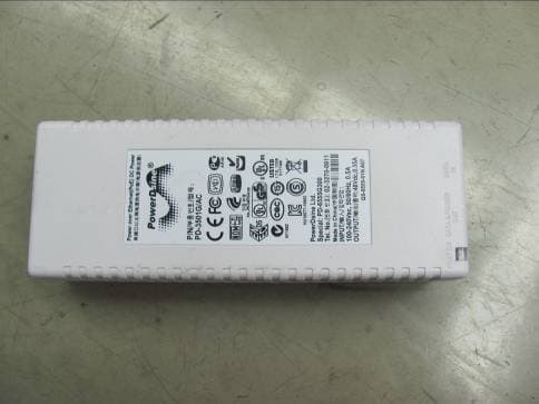
Click to zoom
Application Details
- Equipment Class
- DTS - Digital Transmission System
- Date of Grant
- May 29, 2012
- Application Purpose
- Original Equipment
- Date of Application
- May 14, 2012
- Equipment Note
- Wireless Mesh Router
- Frequency Range
- 5745.00000000 - 5825.00000000
- Country
- United States
Documents & Files
Document Text
Text extracted from the exhibit documents filed with the FCC. Open a document above to read the original.
Users Manual
Aruba Networks MST200 Installation Guide MST200 Installation Guide 1 Copyright 2005-2010 by Aruba Networks, USA. All rights reserved. Statement of Conditions In the interest of improving internal design, operation function, and/or reliability, Aruba Networks reserves the right to make changes to products described in this document without notice. Aruba Networks does not assume any liability that may occur due to the use or application of the product(s) described herein. DISCLAIMER: LIMITATION OF LIABILITY 1.Before installation, it’s strongly recommended and requested that users pay particular attention to the safety warnings in the sequentially detailed operation procedures within the manual. If there’s any uncertainty or incapability of solving problems, contact the company’s customer support center. Please DO NOT incur any risk or try to verify situations by yourself. Otherwise, any consequence caused by the attempt shall be completely due to the user himself. 2.Please periodically check whether the installed MST200 is damaged, worn-out or poses any danger. Any actual proof, sign or phenomenon of the afore-mentioned situations should be brought to the attention of the company at point of sale. Please DO NOT attempt to repair the product or replace any component. Otherwise, for any consequence arising out of or relating to the users’ attempt repair the product, including but not limited to damages, disuse, short circuit, fire, bodily injury, etc., the company shall not be liable. 3. Users shall purchase or use the company’s MST200 voluntarily. Users shall understand on their own initiative and abide voluntarily by policies, regulations or laws of their respective nation or local territories. The consequence arising out of or relating to any violation of the local laws or regulations by the user, shall be solely imputed to the user himself, and the company shall not be liable. 4. The company disclaims any and all warranties and guarantees, express, implied or otherwise, arising, with respect to the MST200 products or services, including but not limited to the warranty of merchandisability, the warranty of fitness for a particular purpose, and any warranty of non-infringement of the intellectual property rights of any third party. Liability of the company for loss is limited to the total amount paid to the company by the customer during the previous calendar year. The company will have no obligation or liability, whether arising in contract (including Warranty), tort (including active, passive or imputed negligence, strict liability or product liability) or otherwise for any special, incidental, MST200 Installation Guide 2 consequential or indirect damages including but not limited to loss of use, loss of data, business interruption, loss of revenue, loss of business or other financial loss arising out of or in connection with any of the products or other goods or services furnished by the company under this manual, even if advised of the possibility of such damages. 5.It shall never be understood that the manual expresses or implies to any customer or any third party authorize or transfer any rights. The company reserves fully the final interpretation of the MST200 and this manual. Safety Warnings The MST200 must be installed by trained professional installation technicians. All warnings below must be read and understood before installation. General Safety Warnings You can be killed or injured if performing antenna installation near electrical power lines. Carefully read and follow all instructions in this guide. Please be sure there are no high voltage and electronic fields nearby. Working Aloft Warning When working on tower or roof, individuals must wear safety belts. Tools must be tied to the individual using them. Workers below must wear safety helmets. Lightning Activity Warning Make sure not to connect or disconnect cables during periods of lightning activity. A surge protective device should be installed to prevent potential damage from very high surges, for instance, the peak surges caused by lightning. MST200 Installation Guide 3 Explosive Device Proximity Warning Do not operate wireless network devices close to explosive merchandise or in explosive environments, for example, in the vicinity of a gas station. Antenna Placement Warning Do not install any antenna near overhead power lines or other electric light, or where the antenna can come into contact with such circuits. Antenna Selection Warning Please use DC grounding antenna with lightning protection to prevent surge and static electricity. Grounding Warning Please always remember to protect your MST200 system by installation of grounding lines. The ground connection must be complete before connecting power to the MST200 enclosure. The requirement of grounding is to make sure the resistance must be less than 5 ohm between the ground termination point to grounding tier. Power Installation Warning The installation of the power switch must be performed by a trained professional technician. The power switch is not supplied with the MST200. The power cord must be assembled by a professional installer, and the final assembly must comply with related requirements. MST200 Installation Guide 4 Solar Irradiation and High Temperature Protection Pay attention to level of sunlight, which can increase the working temperature of MST200 to higher than specifications allow. A solar shield is provided in the Aruba standard package and should be installed to protect any outdoor MST200. The Aruba Warrantee policy does not cover those outdoor products for which Solar shields are not installed. Please contact Aruba technical support engineers for detailed information. RF Device Protection Before powering up the MST200, the RF port must be connected to an antenna or a valid load (not included in the standard accessories for MST200). Otherwise, the RF module may be burned out. Aruba will not take any responsibility for such damage. For RF module w…
Text truncated - open the document above for the full version.
Cover Letter(s)
AUTHORIZATION LETTER FCC ID :Q9DMST200 Data: March 5 ,2012 TO whom it may concern: We ,the undersigned, hereby authorize intertek Shanghai of China to act on our behalf, as our agent, in the following matters related to the FCC approval of our products: report submittal, related correspondence , the singing of all documents relating to these matters, and any carried out by Intertek Shanghai within the scope of this authorization shall have the same effects as our own. This authorization shall expire 6 months from original data. If you have any questions regarding the authorization, please don’t hesitate to contact me. Thank you Sincerely, Ivaylo Tankov Compliance Manager Aruba Networks,Inc. Tel :+1 408 754 3035 Email: [email protected]
Cover Letter(s)
Declaration About Equipment Labels We, Aruba Networks, Inc. declare that the label containing our name, model number and certification number would be affixed on our equipment in such a manner as not to be removable except by destruction or defacement. Date: March 5 , 2012 Signature: Signature name: Ivaylo Tankov Title: Compliance Manager
External Photos
FCC ID: Q9DMST200 IC: 4675A-MST200 Page 1 of 3 External Picture FCC ID: Q9DMST200 IC: 4675A-MST200 Page 2 of 3 FCC ID: Q9DMST200 IC: 4675A-MST200 Page 3 of 3 POE
ID Label/Location Info
LABEL,DEVICE,ARUBA,MST2H13N0 COLOR OF BASE: MATERIAL PRIMARY COLOR OF FONT: BLACK SN: XXXXXXXXXXXXXX XXXXXXXXXXXX MAC: SILVER MATT PET,T=0.05, BACKSIDE ADHESIVE MATERIAL 85.5mm 40.0mm R 2.0mm,4PLS MODEL: MST2H13N0 FCC ID: Q9DMST200 IC: 4675A-MST200 5. UL APPROVED INK & MATERIAL 02 R 003ZWA110762 003BVA101372 003DVA110761 003WWA100832 003XWA100833 6. REQUIREMENT FOR ADHESIVE GLUE: 3M-467 CMIIT ID: 2011AJ4504 SPEC: 48V IP66 0.3A 7. Barcode Font: Code 39 4010951 401095102 02 LABEL,DEVICE,ARUBA,MST2H13N0 COLOR OF BASE: MATERIAL PRIMARY COLOR OF FONT: BLACK SN: XXXXXXXXXXXXXX XXXXXXXXXXXX MAC: SILVER MATT PET,T=0.05, BACKSIDE ADHESIVE MATERIAL 85.5mm 40.0mm R 2.0mm,4PLS MODEL: MST2H13N0-US FCC ID: Q9DMST200 IC: 4675A-MST200 5. UL APPROVED INK & MATERIAL 02 R 003ZWA110762 003BVA101372 003DVA110761 003WWA100832 003XWA100833 6. REQUIREMENT FOR ADHESIVE GLUE: 3M-467 CMIIT ID: 2011AJ4504 SPEC: 48V IP66 0.3A 7. Barcode Font: Code 39 4010951 401095102 02
Internal Photos
FCC ID: Q9DMST200 IC: 4675A- MST200 Page 1 of 13 Internal Picture FCC ID: Q9DMST200 IC: 4675A- MST200 Page 2 of 13 RF module FCC ID: Q9DMST200 IC: 4675A- MST200 Page 3 of 13 FCC ID: Q9DMST200 IC: 4675A- MST200 Page 4 of 13 Antenna Internal View of EUT FCC ID: Q9DMST200 IC: 4675A- MST200 Page 5 of 13 Core in PD cable Core in Ethernet cable FCC ID: Q9DMST200 IC: 4675A- MST200 Page 6 of 13 Core in EXP cable FCC ID: Q9DMST200 IC: 4675A- MST200 Page 7 of 13 FCC ID: Q9DMST200 IC: 4675A- MST200 Page 8 of 13 FCC ID: Q9DMST200 IC: 4675A- MST200 Page 9 of 13 FCC ID: Q9DMST200 IC: 4675A- MST200 Page 10 of 13 FCC ID: Q9DMST200 IC: 4675A- MST200 Page 11 of 13 FCC ID: Q9DMST200 IC: 4675A- MST200 Page 12 of 13 FCC ID: Q9DMST200 IC: 4675A- MST200 Page 13 of 13
RF Exposure Info
FCC ID: Q9DMST200 IC: 4675A- MST200 Page 1 of 2 Statement of compliance to Maximum Permissible Exposure (MPE) Applicant : Aruba Networks, Inc. 1322 Crossman Ave., Sunnyvale CA 94089 USA Type/Model : MST2H23N0-XX(where – XX can be any alphanumeric or blank) According to §2.1091, §2.1093 and §1.1307(b), systems operating under the provisions of this section shall be operated in a manner that ensures that the public is not exposed to radio frequency energy level in excess of the Commission’s guidelines. The S = PG / (4πR²) Where S = power density in mW/cm² P = transmit power in mW G = numeric gain of transmit antenna R = distance (cm) As we can see from the test reports SH12020037-001 and SH12020037-002: The maximum P = 20.63Bm = 115.611mW The gain of antenna G = 13dBi = 19.953 R is chosen to be 20cm, S = PG / (4πR²) =115.611 * 19.953 / (4 * 3.14 * 20 * 20) = 0.46mW/cm² This level is below the 1 mW/cm² MPE for General Population / Uncontrolled Exposure as stated in OET BULLETIN 65 Edition 97-01. Date of issue: Sep 16, 2012 Prepared by: Reviewed by: Wakeyou Wang (Project Engineer) Daniel Zhao (Reviewer) FCC ID: Q9DMST200 IC: 4675A- MST200 Page 2 of 2 Appendix I Definition below must be outlined in the User Manual: To satisfy FCC RF exposure requirements, a separation distance of 20 cm or more should be maintained between the antenna of this device and persons during device operation. To ensure compliance, operations at closer than this distance is not recommended.
Test Report
FCC ID: Q9DMST200 IC: 4675A-MST200 Page 1 of 86 EMC TEST REPORT for Intentional & Unintentional Radiator No. SH12020037-002 Applicant : Aruba Networks, Inc. 1322 Crossman Ave., Sunnyvale CA 94089 USA Manufacturer : Aruba Networks, Inc. 1322 Crossman Ave., Sunnyvale CA 94089 USA Product Name : Wireless Mesh Router Type/Model : MST2H23N0-XX(where – XX can be any alphanumeric or blank) SUMMARY The equipment complies with the requirements according to the following standard(s): 47CFR Part 15 (2010): Radio Frequency Devices ANSI C63.4 (2003): American National Standard for Methods of Measurement of Radio-Noise Emissions from Low-Voltage Electrical and Electronic Equipment in the Range of 9 kHz to 40 GHz RSS-210 Issue 8 (December 2010): Low-power Licence-exempt Radiocommunication Devices (All Frequency Bands): Category I Equipment RSS-Gen Issue 3 (December 2010): General Requirements and Information for the Certification of Radiocommunication Equipment ICES-003 Issue 4 (February 2004): Digital Apparatus Date of issue: March 16, 2012 Prepared by: Reviewed by: Wakeyou Wang (Project Engineer) Daniel Zhao (Reviewer) FCC ID: Q9DMST200 IC: 4675A-MST200 Page 2 of 86 Description of Test Facility Name: Intertek Testing Services Limited Shanghai Address: Building No.86, 1198 Qinzhou Road(North), Shanghai 200233, P.R. China FCC Registration Number: 236597 IC Assigned Code: 2042B-1 Name of contact: Steve Li Tel: +86 21 64956565 ext. 214 Fax: +86 21 54262335 ext. 214 FCC ID: Q9DMST200 IC: 4675A-MST200 Page 3 of 86 Content SUMMARY .......................................................................................................................................................... 1 1. GENERAL INFORMATION ............................................................................................................................ 5 1.1 Applicant Information ..................................................................................................... 5 1.2 Identification of the EUT ................................................................................................ 5 1.3 Technical specification ................................................................................................... 6 1.4 Mode of operation during the test / Test peripherals used .............................................. 7 2. TEST SPECIFICATION .................................................................................................................................. 8 2.1 Instrument list ................................................................................................................. 8 2.2 Test Standard .................................................................................................................. 8 2.3 Test Summary ................................................................................................................. 9 2.4 Chain Power .................................................................................................................. 10 2.5 Data rate VS power ....................................................................................................... 11 3. MINIMUM 6DB BANDWIDTH ..................................................................................................................... 12 3.1 Limit .............................................................................................................................. 12 3.2 Test Configuration ........................................................................................................ 12 3.3 Test Procedure and test setup ........................................................................................ 12 3.4 Test Protocol ................................................................................................................. 13 4. MAXIMUM PEAK OUTPUT POWER ............................................................................................................. 22 4.1 Test limit ....................................................................................................................... 22 4.2 Test Configuration ........................................................................................................ 22 4.3 Test procedure and test setup ........................................................................................ 22 4.4 Test protocol ................................................................................................................. 23 5. POWER SPECTRUM DENSITY ..................................................................................................................... 34 5.1 Test limit ....................................................................................................................... 34 5.2 Test Configuration ........................................................................................................ 34 5.3 Test procedure and test setup ........................................................................................ 34 5.4 Test Protocol ................................................................................................................. 35 6. RADIATED EMISSION ................................................................................................................................. 46 6.1 Test limit ....................................................................................................................... 46 6.2 Test Configuration ........................................................................................................ 46 6.3 Test procedure and test setup ........................................................................................ 47 6.4 Test protocol ................................................................................................................. 48 7. EMISSION OUTSIDE THE FREQUENCY BAND ...................................................................................…
Text truncated - open the document above for the full version.
Test Setup Photos
FCC ID: Q9DMST200 IC: 4675A- MST200 Page 1 of 7 Test Setup FCC ID: Q9DMST200 IC: 4675A- MST200 Page 2 of 7 1. Radiated Emission from the EUT cabinet 30MHz-1000MHz FCC ID: Q9DMST200 IC: 4675A- MST200 Page 3 of 7 1GHz-18GHz FCC ID: Q9DMST200 IC: 4675A- MST200 Page 4 of 7 Higher than 18GHz FCC ID: Q9DMST200 IC: 4675A- MST200 Page 5 of 7 2. Mains Conducted emission FCC ID: Q9DMST200 IC: 4675A- MST200 Page 6 of 7 3. Antenna RF Conducted emission FCC ID: Q9DMST200 IC: 4675A- MST200 Page 7 of 7 4. Conducted Average Output Power
Contact Information
Applicant
Mark Hill(Principal Engineer)
Technical Contact
Intertek Testing Services Limited ShanghaiWakeyou Wang
[email protected]86 21 61278448
Building No.86, 1198 Qinzhou Road(North) · Shanghai · China
Non-Technical Contact
Intertek Testing Services Limited ShanghaiWakeyou Wang
[email protected]86 21 61278448
Test Firm
Intertek Testing Services Limited ShanghaiJonny Jing
Technical Specifications
| # | Rule Parts | Frequency Range | Power Output |
|---|---|---|---|
| 1 | 15C | 5.75 GHz - 5.83 GHz | 116.00 mW |
Other Applications from Hewlett Packard Enterprise Company
Q9DAPINH721
Jul 17, 2026Access Point
Equipment Class
6ID - 15E 6 GHz Low Power Indoor Access PointQ9DASIN0307
Dec 22, 2025HPE Aruba User Experience Sensor
Equipment Class
DTS - Digital Transmission SystemQ9DASIN0308
Nov 23, 2025HPE Aruba User Experience Sensor
Equipment Class
DTS - Digital Transmission SystemQ9DAPEX0764
Nov 20, 2025ACCESS POINT
Equipment Class
DTS - Digital Transmission SystemQ9DAPIN0763
Sep 29, 2025ACCESS POINT
Equipment Class
NII - Unlicensed National Information Infrastructure TX