Q9V-400-ALow Power Transceiver
Radianse, Inc.
Click to zoom
Application Details
- Equipment Class
- DXT - Part 15 Low Power Transceiver, Rx Verified
- Date of Grant
- Oct 09, 2003
- Application Purpose
- Original Equipment
- Date of Application
- Oct 09, 2003
- Equipment Note
- Low Power Transceiver
- Frequency Range
- 433.92000000 - 433.92000000
- Company
- Radianse, Inc.
- Country
- United States
Documents & Files
Document Text
Text extracted from the exhibit documents filed with the FCC. Open a document above to read the original.
Users Manual
Indoor Positioning Installation and Users Guide v1.0 7/15/2003 Installation and Users Guide Indoor Positioning Installation and Users Guide v1.0 7/15/2003 Safety and Regulatory Information FCC FCC ID: Q9V-100-A Radianse Indoor Location Systems This device complies with Part 15 of the FCC Rules. Operation is subject to the following two conditions: (1) this Device may not cause harmful interference and (2) this Device must accept any interference received, including Interference that may cause undesired operation. Caution! Radianse Inc. warns the user that changes or modifications to the unit not expressly approved by the party responsible for compliance could void the user’s authority to operate the equipment. Industry Canada The term IC: before the certification number only signifies that the Industry Canada technical specifications were met. Indoor Positioning Installation and Users Guide v1.0 7/15/2003 Installation Preparation Prior to installation, the location of all LanPaks needs to be determined. A detailed map of the areas to be covered will be required. These should be in .dwg or .dwx format and provided to Radianse as early as possible. This map will be the basis for determining the positions of the LanPaks throughout your facility. With the initial positions determined a final walkthrough to determine exact locations will be required. At this time, any physical issues that will impact the ability to install (ex. light fixtures, cabinets, etc) will be taken into account and final positioning will be verified. A Radianse team member will work with you to complete this task. In addition to the LanPak installation you should prepare the necessary information for the LightPak installation. A detailed list of any resources that will be tracked should be obtained. This could include a staff roster and/or equipment inventory. LanPak Installation Members of the Radianse team will install the LanPaks. Prior to installation, you should ensure that all network ports have been installed, activated and tested. For installations using power over UTP, this includes the installation and testing of the power injectors. For installations not using power over UTP, the installation and location of electrical outlets should be verified. A Radianse team member will be on-site for the installation of the LanPaks. As a result, detailed installation and configuration instructions are not included. Should a LanPak require replacement, any replacement equipment will be shipped to you pre-configured and ready to be plugged into your network. Should you need to remove an installed LanPak, slide the LanPak upward and then away from the wall to remove it from the bracket. Unplug the power cord (if one exists) from the back of the LanPak (Note: most LanPaks will not have a separate power cord) and then unplug the network cable from the LanPak. With the old LanPak removed, you can now install the new LanPak. Plug the network cable and the power cable (if one exists) back into the LanPak. Place the new LanPak on the bracket, lining up the mounting holes, and slide the LanPak downward to lock it into place. Plug the network cable back into the data port. Once installed, any extra cable can be tucked behind the LanPak. LightPak LightPaks come preconfigured and ready for use. There is no hardware setup required. Indoor Positioning Installation and Users Guide v1.0 7/15/2003 LightPak assignment Equipment: You will use the Data Management Console to assign a LightPak to a piece of equipment. First select the appropriate LightPak from the tree in the Data Management Console. Enter key equipment information (make, model, type, serial number, etc). People The Data Management Console can be used to assign a LightPak to an individual, similar to equipment. In addition, individual assignments can be made using the Assign Tool. In the Assign Tool, first enter the LightPak number, and then enter the appropriate information on the staff member, or patient and click <enter>. Software Installation Guide • Server Requirements o 1.6 GHz Pentium III or greater, 20Gbytes of free disk space, minimum, 256M RAM minimum. o Operating System: Windows 2000 or XP o MySQL Rev 3.23 (minimum) o Database link: MYODBC Rev 2.5 (minimum) or J2SE Rev 1.4 (minimum) o Java 1.4.1 (minimum) o XML: Rev 1.0 (minimum) o Tomcat: Rev 4.1.18 (minimum) A Radianse team member will be on site for the installation and configuration of the server. Therefore, no detailed instructions for configuration are included in this document. Should you need to change the server after the system is live, you should work with the Radianse customer service team to accomplish this.
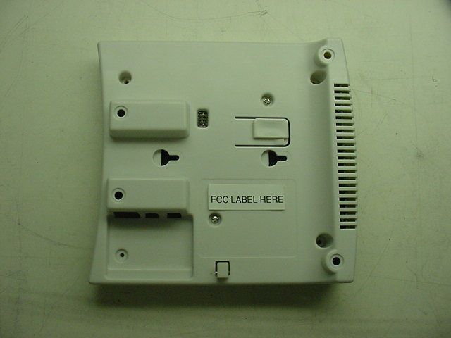
ID Label/Location Info
67 53 4X R2.92 25.40 KISS-CUT RELEASE LINERON REAR OF LABEL. NOTES:1. MATERIAL: 4 MIL (.004") POLYCARBONATE LABEL. WHITE BACKGROUND. BLACK INK TEXT.2. ADHESIVE: 3M DOUBLE SIDED.3. RELEASE LINER ON FARSIDE. D C B A ABC D 1 2 3 4 5 6 7 8 8 7 65 4 3 2 1 THE INFORMATION CONTAINED IN THISDRAWING IS THE SOLE PROPERTY OFRADIANSE INC. ANY REPRODUCTION IN PART OR AS A WHOLE WITHOUT THEWRITTEN PERMISSION OF RADIANSE INC. IS PROHIBITED. PROPRIETARY AND CONFIDENTIAL NEXT ASSY USED ON APPLICATION INTERPRET GEOMETRICTOLERANCING PER: MATERIAL FINISH SEE NOTES. SEE NOTES. DRAWN CHECKED ENG APPR. MFG APPR. Q.A. COMMENTS: DATE NAME RADIANSE INC. TITLE: SIZE B DWG. NO. SHEET 1 OF 1 WEIGHT: SCALE: 2:1 REVISIONS REV. DESCRIPTION DATE APPROVED ZONE UNLESS OTHERWISE SPECIFIED: LABEL, RECEIVERMODEL 400A SW-80001 HENDERSON 02/20/03 1 PRE-PRODUCTION RELEASE. 02/20/03 DIMENSIONS ARE METRIC.TOLERANCES:FRACTIONAL ANGULAR: MACH BEND ONE PLACE DECIMAL .3TWO PLACE DECIMAL .13 07/31/03 LABEL CHANGED. 2 3 LABEL TEXT CHANGED. 08/09/03
Test Report
RETLIF TESTING LABORATORIES TEST REPORT R-4155N4 September 24, 2003 FCC COMPLIANCE TEST REPORT ON RADIANSE, INC. INDOOR POSITIONING TRANSCEIVER FCC ID: Q9V-400-A Test Report No. R-4155N4 FCC ID: Q9V-400-A APPLICANT Radianse, Inc. 439 South Union Street, Suite 401 Lawrence, MA 01843 MANUFACTURER SAME TEST SPECIFICATION: FCC Rules and Regulations Part 15, Subpart C, Para. 15.231 (e) TEST PROCEDURE: ANSI C63.4:1992 TEST SAMPLE DESCRIPTION BRANDNAME: LanPak MODEL: 400A TYPE: Indoor positioning/asset location system transceiver (Receiver verified) POWER REQUIREMENTS: DC via 120VAC, 60Hz external power supply FREQUENCY OF OPERATION: 433.92MHz TYPE OF TRANSMISSION: Pulsed emission containing manchester encoded data bits FCC ID: Q9V-400-A APPLICABLE RULE SECTION: Part 15, Subpart C, Section 15.231 (e) TESTS PERFORMED 15.231 (e) Spurious Emissions (30MHz to 4.4GHz) 15.231 (e) Field Strength of Fundamental (433.92MHz) 15.231 (c) Occupied Bandwidth, 0.25% of Fundamental Frequency 15.207 (a) Conducted Emissions Duty Cycle Determination TEST SAMPLE OPERATION The EUT is dc powered via an external 120VAC, 60Hz power supply. The device is normally manually operated but can be programmed to operate automatically. The device transmits a 433.92MHz signal used to calibrate associated system receivers. Operation of the EUT complies with the parameters required in Part 15, Subpart C, Section 15.231 (e) for devices which will transmit data and with the general requirements of 15.231 for both automatic and manual operated devices. For testing purposes only the EUT was configured to continuously transmit. Test Report No. R-4155N4 FCC ID: Q9V-400-A TEST SAMPLE / TEST PROGRAM CWhen manually activated the transmitter automatically ceases transmission within five seconds after activation per the requirements of 15.231 a (1). CIn automatic mode the transmitter ceases transmission within 5 seconds after activation per the requirements of 15.231 a (2). •In automatic mode operation is limited so that the duration of each transmission is less than one second (8.016msec) and the silent period between transmissions is more than 30 times the duration of the transmission and over ten seconds per the requirements of 15.231 (e) . CThe device is not employed for RC purposes involving fire, security and safety of life. CThe fundamental field strength at 433.92MHz did not exceed 4398μV/M (Average) at a test distance of 3 meters. •The peak value of fundamental emissions did not exceed a peak field strength limit corresponding to 20dB above the maximum permitted average limit. CThe field strength of harmonic and spurious emissions did not exceed 439μV/M as specified in 15.231 (e) for a fundamental frequency of 433.92MHz. CThe device operates at a single frequency of 433.92MHz The bandwidth of emissions did not exceed 0.25% of the operating frequency as specified in 15.231 (c) and was determined as follows: Fundamental Frequency=433.92MHz 0.25% of Center Frequency=1.0848MHz 1.0848 divided by 2=0.542MHz Bandwidth Range=Fundamental Frequency + and - 0.542MHz 433.92MHz - 0.542MHz=433.378MHz 433.92MHz + 0.542MHz=434.462MHz Bandwidth Range=433.378MHz - 434.462MHz CThe device uses an internal loop antenna CRadiated Emissions from the EUT were measured in all three axis. The attached Radiated Emissions test data is representative of the worst case orientation. Test Report No. R-4155N4 FCC ID: Q9V-400-A DETERMINATION OF FIELD STRENGTH LIMITS The field strength limits shown below were calculated as instructed in Section 15.231 (e). Fundamental Frequency: 433.92MHz Where F is the frequency in MHz, the formula for calculating the maximum permitted fundamental field strength for the band 260-470MHz, μV/m at 3 meters is as follows: 16.6667(F) - 2833.3333 =Field Strength Limit (μV/m) 16.6667 x 433.92=7232 7232 - 2833.3333=4398 Field Strength Limit=4398 μV/m = 72.8dBuV/M The maximum permitted unwanted emission level is 20dB below the maximum permitted fundamental level which equals 439.8 μV/m = 52.8dBuV/M. DETERMINATION OF DUTY CYCLE The transmitter controls were adjusted to maximize the transmitted duty cycle. The analyzer was set for a frequency span of 0Hz. The sweep time was then adjusted in order to display one full pulse train. The transmitter on time was then summed and compared to the time for one full cycle in order to obtain the duty cycle. As the pulse train was less than 100msec in duration the worst case duty cycle was determined by measuring/calculating the duration of the pulse train and then the “on time” within the pulse train. The on times were determined as follows: The individual pulse widths within the pulse train were measured and summed in order to obtain the total “on time” within the train. Fundamental Frequency: 433.92MHz Transmitter On Time=4.0865 milliseconds Transmitter Cycle Time=8.016 milliseconds Transmitter Duty Cycle=50.98 % On Time divided by Cycle Time=Duty Cycle Factor 4.0865 divided by 8.016=0.5096 10 0.5096 converted to dB (LOG .05096)20=-5.85dB Duty Cycle Factor=-5.85dB As the measured peak field strength of the transmitter was less than the specified average limit without applying the Duty Cycle Correction Factor the duty cycle determination plots have not been included as an exhibit and the duty cycle factor was not applied to the final field strength readings. Test Report No. R-4155N4 FCC ID: Q9V-400-A TEST SAMPLE / TEST PROGRAM (continued) SPECTRUM ANALYZER Due to the nature of the emissions being measured, care was taken to ensure that the resolution bandwidth of the spectrum analyzer was adequate to provide accurate measurements. GENERAL NOTES 1.All readings were taken utilizing a peak detector function at a test distance of 3 meters. Test Report No. R-4155N4 FCC ID: Q9V-400-A EQUIPMENT LISTS Conducted Emissions ENTypeManufacturerDescriptionModel No.Cal DateDue Date 4027LISNSolar Electronics10 KHz - 30 MHz9252-50-R-24BNC10/02/200210/02/2003 4028Isolation TransformerAcmeN/A120x24001/08/200301/08/2004 40…
Text truncated - open the document above for the full version.
Contact Information
Applicant
Paul Tessier(VP of Engineer)
Technical Contact
Retlif Testing LaboratoriesScott Wentworth
[email protected]603-497-4600
101 New Boston Road · Goffstown, New Hampshire · United States
Non-Technical Contact
Retlif Testing LaboratoriesScott Wentworth
[email protected]603-497-4600
Test Firm
Retlif Testing LaboratoriesScott Wentworth
Technical Specifications
| # | Rule Parts | Frequency Range | Power Output |
|---|---|---|---|
| 1 | 15C | 433.92 MHz - 433.92 MHz | - |
Other Applications from Radianse, Inc.

Q9V-350-A2
Feb 27, 2007Transmitter Used for Location Information
Equipment Class
DSC - Part 15 Security/Remote Control Transmitter
Q9V-110-A
Aug 01, 2006Low Power Transmitter Used for Location Informatio
Equipment Class
DXX - Part 15 Low Power Communication Device Transmitter
Q9V-350-A
May 10, 2006Low Power Transmitter Used to Transmit Location
Equipment Class
DXX - Part 15 Low Power Communication Device Transmitter
Q9V-100-A
Oct 09, 2003Low Power Transmitter
Equipment Class
DXX - Part 15 Low Power Communication Device Transmitter