QANKRB1011108Multi Carrier Power Amplifier
Powerwave Technologies, Inc.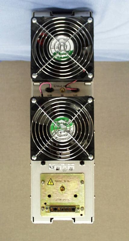
Click to zoom
Application Details
- Equipment Class
- AMP - Amplifier
- Date of Grant
- Apr 25, 2002
- Application Purpose
- Original Equipment
- Date of Application
- Apr 25, 2002
- Equipment Note
- Multi Carrier Power Amplifier
- Frequency Range
- 869.00000000 - 894.00000000
- Company
- Powerwave Technologies, Inc.
- Country
- United States
Documents & Files
Document Text
Text extracted from the exhibit documents filed with the FCC. Open a document above to read the original.
Users Manual
ERICSSON AMPLIFIER TECHNOLOGIES INC. 49 Wireless Boulevard Hauppauge, New York 11788 (631) 357-8200 MULTI-CARRIER POWER AMPLIFIER MCPA Product Number 1/KRB 101 1108 INSTALLATION, OPERATION AND MAINTENANCE INSTRUCTIONS Ericsson Amplifier Technologies Inc. Technical Publication MCPA Revision A PREPARED May 23, 2001 NOTICE PROPRIETARY AND PRIVATE The information contained in this document is the property of Ericsson Amplifier Technologies Inc., (Company) and shall be kept in strict confidence. Except with the written permission of the Company, such information shall not be published, or disclosed to others, or used for manufacture or sale or for any other purpose. This document shall not be duplicated in whole or in part. Any recipient so agrees by acceptance of this document. © 2001 – Ericsson Amplifier Technologies Inc.i The following symbols are used throughout this technical manual: WARNING THIS SYMBOL INDICATES IMPORTANT INFORMATION THAT IS EMPHASIZED TO ALERT THE READER TO THE POTENTIAL RISK OF PERSONAL INJURY TO THE OPERATOR OR OTHER PERSONNEL. CAUTION This symbol indicates important information that is emphasized to alert the reader to the potential risk of damage to the amplifier. NOTE This symbol indicates information that is highlighted signifying an operation or procedural step requiring additional emphasis. Ericsson Amplifier Technologies Incorporated provides this technical manual “as is” without warranty of any kind, either expressed or implied. Ericsson Amplifier Technologies may make improvements or changes to the product and/or manual at any time without notice. Every effort has been made to ensure the accuracy and completeness of this technical manual, however, it may contain technical inaccuracies or typographical errors. Changes are made periodically to the information contained herein. These changes will be incorporated into new editions of this technical manual. Ericsson Amplifier Technologies is interested in receiving comments from the users of this manual in order to improve its usefulness. All comments should be directed via regular mail to the address listed on the title page of this document. Ericsson Amplifier Technologies may use or distribute any of the information supplied in any way it believes appropriate, without incurring any obligations. All specifications are subject to change without notice. WARNING THE USE OF AN EARTH GROUND IS REQUIRED TO ENSURE SAFETY. IF THE EQUIPMENT APPEARS TO BE DAMAGED IN ANY WAY, REMOVE ALL POWER TO THE UNIT, AND HAVE IT SERVICED AS SOON AS POSSIBLE. © 2001 – Ericsson Amplifier Technologies Inc.iv RETURN FOR REPAIR FIELD OPERATION SUMMARY SHEET Please make a copy of this sheet, and complete the following questionnaire. If necessary, attach additional sheets. This information will assist in expediting repairs to the equipment, and is used for fault trend analyses and ongoing product improvement. FIELD TECH NAME:_______________________________ DATE:_____________________________ EQUIPMENT LOCATION (CELL SITE NUMBER):___________________________________________ ____________________________________________________________________________________ MODEL NUMBER:____________________________________________________________________ SERIAL NUMBER:____________________________________________________________________ FREQUENCY OF OPERATION: A:__________________________ B: _________________________ CARRIER POWER:____________________________________________________________________ MAXIMUM NUMBER OF CARRIERS:_____________________________________________________ LED INDICATOR STATUS: LED DESCRIPTIONLED ON Check ̨ LED OFF Check ̨ DC ON: oo ENABLE: oo FAN ALARM: oo LOOP ALARM: oo VSWR ALARM: oo POWER SUPPLY ALARM: oo TEMPERATURE ALARM: oo OVER POWER ALARM: oo UNIT SURFACE TEMPERATURE:_______________________________________________________ POWER SUPPLY MODEL OR CAPABILITY:_______________________________________________ ____________________________________________________________________________________ OTHER DETAILS OF PROBLEM REPORTED:______________________________________________ ____________________________________________________________________________________ ____________________________________________________________________________________ © 2001 – Ericsson Amplifier Technologies Inc.v Table of Contents 1.GENERAL DESCRIPTION.....................................................................................1 1.1Introduction.............................................................................................................................1 1.2Related Publications...............................................................................................................1 1.3General Description.................................................................................................................1 1.4Equipment Functional and Physical Specifications..............................................................2 1.5Mechanical Description...........................................................................................................3 2.INSTALLATION.....................................................................................................4 2.1Introduction.............................................................................................................................4 2.2Electrical Service Recommendations.....................................................................................4 2.3Receiving, Unpacking and Inspection....................................................................................4 2.4Repackaging for Shipment.....................................................................................................4 2.5Environmental Limitations......................................................................................................5 2.6Installation................................................................................................................…
Text truncated - open the document above for the full version.
Block Diagram
Ericsson Amplifier Technologies Inc. 49 Wireless Boulevard Hauppauge, New York 11788Telephone: +1 (631) 357-8200 Ma in A mp Dr iver Main Amp Pilot tone RCVR De lay Li ne Output Coupler Class A Delay Line Carrier Cancellation Booster Amp E rro r Amp Carrier Cancellation Detector To Control Bd To Contro Bd To Control Bd MCPA Block Diagram RF Input -7 dB Test Point -1 2 d B 20 nS RF out Power Supply Bd Loop/IMD Control Bd To Control Bd Frequency RF In = Frequency RF out. LO = 44.545 MHz
Cover Letter(s)
Ericsson Amplifier Technologies Inc. 49 Wireless Boulevard Hauppauge, New York 11788Telephone: +1 (631) 357-8200 Thursday, April 25, 2002 Federal Communications Commission Office of Engineering Technology 7435 Oakland Mills Road Columbia Maryland 21046 Gentlemen, In applying for certification (type acceptance) for the Multi Channel Power Amplifier Sub-System KRB 101 1108 and Sub-rack BFL 119 97/1, Ericsson Amplifier Technologies requests that certain items be withheld from public inspection. This request is made in accordance with FCC section 0.459 (a) & (b). The documentation submitted for review with the request for type certification includes trade secrets, which if made publicly available would seriously injure Ericsson Amplifier Technologies competitive advantage. Ericsson Amplifier Technologies competition could gain advantage by studying these documents and acquire the unique design features of our amplifier. The unique design features are Ericsson Amplifier Technologies trade secrets that allow Ericsson Amplifier Technologies to competitively produce an amplifier with respect to the number of carriers, modulation standards and power level(s), etc. The documents that Ericsson Amplifier Technologies requests confidentiality (Non Disclosure) are: Enclosure 6Detailed circuit diagrams and assembly drawings including parts lists, in the Multi-Channel Power Amplifier and Sub-rack Assembly. Regards, Name: John Mellon Title: Associate Engineer. Ericsson Amplifier Technologies Inc
External Photos
Figure: 1 MCPA FRONT VIEW Figure: 2 MCPA SIDE VIEW Figure: 6 MCPA REAR VIEW. Figure: 4 MCPA SIDE VIEW.
ID Label/Location Info
Rev. B LABELS AB502730-10 ITEM 1 A&WINSP TEST FINAL ASSY/EB502620-3SERIAL NO.XXXXXX ITEM 2 U10XXXXXXXYYWXX 1/KRB 101 1108R2A ERICSSON ITEM 3 Rev. B ITEM 4 ITEM 5 ITEM 6 FCC ID: QANKRB1011108
Internal Photos
Figure: 3 MCPA SIDE VIEW - COVER REMOVED Figure: 5 MCPA SIDE VIEW – COVERS REMOVED
Operational Description
Operational description 4.1 Introduction This section contains a functional description of the multi-carrier power amplifier. 4.2 RF Input Signal The maximum input signal for all carrier frequencies must not exceed the limits specified in the electrical specifications. The input VSWR should be 2:1 maximum (or better). 4.3 RF Output Load The load impedance should be as close as possible to 50 ohms (VSWR of 1.5:1 or less) over the 869-894 MHz operating frequency band to ensure maximum RF power transfer to the load. 4.4 System Functional Description The MCPA amplifier is a multi-carrier, feed forward power amplifier, which operates from 869 to 894 MHz with a rated output power of 120W total (average). The amplifier employs feed forward carrier cancellation circuitry, providing extremely low intermodulation products, equal to or less than –63 dBc. The front panel of the amplifier contains the DC ON/OFF switch, and the status LEDs. The amplifier operates from a 26-28 VDC input power source, and provides a rear panel input/output (I/O) control and status interface to report all faults and alarms. Relay dry contacts are provided for the following fault conditions: OVERPWR – Relay dry contact closure provided for remote notification in the event that the MCPA output is greater than 2 dB above the nominal operating power level. The MCPA power will need to be reset in order to clear this fault condition. MINORFLT – Relay dry contact closure provided for remote notification in the event that the MCPA has encountered a minor fault condition, which has not caused shut down of the amplifier, but which will require attention as soon as possible in order to ensure uninterrupted operation. A TEMP WARNI NG or FAN ALARM will result in a MINORFLT condition and remote notification. The MCPA power will need to be reset in order to clear this fault condition. MAJORFLT – Relay dry contact closure provided for remote notification in the event of a potentially damaging fault condition, which has resulted in shut down of the MCPA. Activation of the LOOP ALARM, VSWR ALARM, POWER SUPPLY ALARM, TEMP ALARM and OVERPOWER ALARMS will result in a MAJORFLT condition and remote notification. The MCPA power will need to be reset in order to clear this fault condition. TTL control inputs are provided at the I/O interface. The Control and Status interface is an 8-bit asynchronous serial bus, which complies with the EIA/TIA 232-E type Standard for Electrical Characteristics for use in Balanced Digital Systems. The communications protocol is as follows: • Half D upl e x • 1 Start bit • 1 Stop bit • 8 Data bits • No Parity • 9600 bits per second (baud) The MCPA will respond to commands, and will send a response only when commanded first. Although the MCPA contains no user-serviceable components (with the exception of the fan assemblies), the following paragraphs provide operating principles, and a general overview of its operation. The amplifier is comprised of the following internal functional elements: • Carrier Cancellation • Main/Error Driver Amplifier • Main Amplifier • Error Amplifier • DC/DC Function • Microprocessor Control • Loop Processor • Pre-distorter The main amplifier employs class AB amplification for maximum efficiency and low intermodulation distortion. The error amplifier and main/error driver amplifiers operate class A mode. The input RF signal is amplified by the carrier cancellation circuit, and then split into a signal and a reference path. The signal path is sent through the main driver amplifier, where the amplitude and phase are modified, based on the reference signal, and then amplified by the main amplifier. The signal is coupled to the carrier cancellation circuit where the 180 ° phase shifted and amplified signal meets the reference signal. At this point the combined signal, which has a canceled carrier (called the IMD signal), is sent to the IMD leg of the feed forward amplifier. The IMD signal is sent to the error driver amplifier and error amplifier. Signal amplitude and phase are adjusted from the input by the loop processor. The signal is re-injected into the main amplifier output signal, and the combined signal yields suppression of intermodulation products of -65 dBc minimum. The following paragraphs describe each of the functional elements of the MCPA. 4.4.1 Main Amplifier The main amplifier operates class AB, and provides approximately 29.5 dB of gain over the operating frequency band of 869-894 MHz. It operates from 27 VDC and utilizes 15 VDC to derive bias. The main amplifier is directly mounted to the heatsink. Within the main amplifier are temperature sensors, which detect the baseplate (heatsink) temperature. In the event that the heatsink temperature reaches approximately +80 °C, the TEMP WARNI NG (yellow) LED will be illuminated. Operation of the MCPA may continue during this condition. In addition, should the heatsink temperature further rise to approximately +90°C, bias to the internal amplifier is shut down to prevent damage during the over temperature condition. The TEMP ALARM (red) LED will be illuminated. Operation of the MCPA is inhibited until the heatsink temperat ure has returned to a safe operating level. The fault condition will automatically self-clear when the heatsink has cooled to a safe level, and normal operation will again be restored. The cause of any TEMP WARNING or TEMP ALARM condition should be investigated as soon as possible to ensure continuous uninterrupted MCPA operation. 4.4.2 Error Amplifier The main function of the error amplifier is to amplify the distortion products generated by the main amplifier. These distortion products are amplified and precisely phaseshifted (180° with those at the output), such that when they are combined with the main signal at the output of the amplifier, the result is cancellation of the distortion products. The error amplifier operates class A, has 57 dB of gain, and produces 2 watts of output. The amplifier operates from 2…
Text truncated - open the document above for the full version.
RF Exposure Info
Enclosure. 7 Multi-Carrier Power Amplifier Subsystem. Product Number: KRB 101 1108 Radio Frequency Radiation Exposure Statement. Ref: 1.1307. National Environmental Policy Act of 1969. The Multi-Carrier Power Amplifier by itself offers no environmental impact. 1.1310. National Environmental Policy Act of 1969. The Multi-Carrier Power Amplifier is integrated into a Base Station Configuration. The Maximum Permissible Exposure (MPE) is determined at the Base Station level. 2.1091. Radio Frequency Radiation Exposure Evaluation: Mobile Devices. Not Applicable. The Multi-Carrier Power Amplifier is not a Mobile Device. 2.1093. Radio Frequency Radiation Exposure Evaluation: Portable Devices. Not Applicable. The Multi-Carrier Power Amplifier is not a Portable Device.
Test Report
An independent organizat ion testing for safey, performance, and certification All services undertaken subject to the following general policy:Reports are submitted for the exclusive use of the clients to whom they are addressed. Their significance is subject to theadequacy and representative character of the samples and to the comprehensiveness of the tests, examinationsor surveys made. No quotation from reports or use of ITS’s name is permitted except asexpressly authorized by ITS in writing. On August 8-10, 2001, we tested the MCPA Power Amplifier, ITS project #3004587 to determine if it met the requirements for amplifiers of FCC Part 22 Subpart H. The equipment under test is: Multi-Carrier Power Amplifier Sub-system, Product Number: KRB 101 1108. Multi-Carrier Power Amplifier Module, Product Number: 1/ KRB 101 1108. 4 Module Sub-rack. Product Number: BFL 119 97/1 Installation and Operating Instructions: The product is a Multi-Carrier Feed Forward Power Amplifier (MCPA ) designed for cellular base station application. It is entirely solid-state and is powered by an external 27VDC power supply. The MCPA when installed in a Sub-rack becomes a Multi-Carrier Power Amplifier Sub-system. A complete technical description is provided in the Manuals, and Detailed Circuit Diagrams. Emissions Types: AMPS F8W (conventional AMPS) AMPS F1D (wideband data conventional AMPS) TDMA DXW CDMA F9W Frequency range: 869-894 Range of operating power: The Multi-Channel Power Amplifier (MCPA) module has a fixed gain of 69.5 dB. The output power is dependent on the applied input power. Under normal operating conditions, the MCPA maximum average output power of 120 watts is not exceeded. The MCPA dynamic range is 20 db. The Sub-system which comprises of a Sub-rack and one to four MCPA’s modules. The output power is dependent on the applied input power. Under normal operating conditions, the maximum average output power of 400 watts is not exceeded. Maximum RF output power: The maximum RF power rating of the MCPA module is 120 watts average standalone. The maximum RF power rating of the Sub-assembly is 400 Watts average. DC Voltage & Current. (At maximum RF Power) MCPA Module Voltage: 26 to 28 Volts. Current: 55 Amps Typical 58 Amps Max. Sub-assembly Voltage: 26 to 28 Volts. Current: 222 Amps Typical 234 Amps Max. Ericsson Amplifier TechnologiesPage 2 of 24Project Number: 3004587 Tune –Up Procedure. The unit is tuned to specification at the factory. There are no user adjustments or tune-up procedures associated with the amplifier. When the amplifier is properly installed in a radio base station (as shown in Fig 1: MCPA environment) the Cellular Radio Exchange (CRE) will supervise and control the output power per carrier. If a fault condition should arise in the amplifier, this is signalled to the CRE. In case of a major fault the amplifier is automatically shutdown. Description of Frequency Determining/Stabilizing Circuits and Devices. Description of Circuits Suppressing Spurious & Limiting Power. The power amplifier does not affect the frequency characteristics of the signals that it amplifies. The unit is a solid –state linear power amplifier; no special or unusual circuitry is utilized to suppress spurious radiation, limit modulation or limit power. The intended FCC ID is: QANKRB1011108 Manufacturer: Ericsson Amplifier Technologies 49 Wireless Blvd. Hauppauge, NY 11788-3935 Person to receive grant: Michael V. Hrybenko, Senior RF Engineering Manager Ericsson Amplifier Technologies 49 Wireless Blvd. Hauppauge, NY 11788-3935 Phone: 631-357-8352 Fax: 631-231-4084 E-mail: [email protected] Technical/Non-Technical Contact: John Mellon, Associate Engineer Ericsson Amplifier Technologies 49 Wireless Blvd. Hauppauge, NY 11788-3935 Phone: 631-357-8291 Fax: 631-231-4084 E-mail: [email protected] Ericsson Amplifier TechnologiesPage 3 of 24Project Number: 3004587 Following are the results of testing. RF Power Output - Passed The amplifier was operated in a typical fashion. The ouput of the EUT was connected through a 40 dB attenuator to an average power meter. Measurements of the EUT output power under various types of modulation were made. These measurements were used elsewhere in testing. It was found that the EUT maintained an approximately 100W output using any modulation scheme. Readings were made at the low, middle, and high frequencies in the passband. The low channel was 869 MHz, the middle channel was 881 MHz, and the high channel was 894 MHz. ChannelTDMACDMAAMPS (audio)AMPS (audio & data) Low50.07 dBm50.06 dBm49.95 dBm50.07 dBm Mid50.11 dBm50.12 dBm50.01 dBm50.04 dBm High50.13 dBm50.05 dBm50.08 dBm50.09 dBm Test Equipment NameBrandModel #:Serial #:Cal. Due Date: Average Power Meter Boonton4232a5560112/20/01 Attenuator, 40 dBWeinschel45-40-43LF899Cal Verified Ericsson Amplifier TechnologiesPage 4 of 24Project Number: 3004587 Occupied Bandwidth - Passed The amplifier was operated in a typical fashion. The output was connected to a spectrum analyzer through a 40 dB attenuator, and measurements were made of the signal 99% bandwidth. The requirement is that the output from the amplifier does not have larger bandwidth than the input signal. Modulation CDMATDMAAMPs (audio)AMPS (audio and data) ChannelInputOutputInputOutputInputOutputInputOutput Low1.26 MHz1.26 MHz28 kHz28 kHz16.5 kHz 16.5 kHz 44.5 kHz 44 kHz Mid1.27 MHz1.27 MHz28 kHz28 kHz16.5 kHz 16.5 kHz 44 kHz43.5 kHz High1.265 MHz1.265 MHz28 kHz28 kHz16.5 kHz 16.5 kHz 44 kHz44 kHz Test Equipment: NameBrandModel #:Serial #:Cal. Due Date: High Frequency Cable Sucoflex104PEACBLSHF2032/21/02 Signal GeneratorHPE4433BUS384407337/8/03 RF FilterHP85420E3427A001771/22/02 EMI Receiver Set W/RF Filter HP85422E3625A001881/22/02 Attenuator, 40 dBWeinschel45-40-43LF899Cal Verified Ericsson Amplifier TechnologiesPage 5 of 24Project Number: 3004587 Field Strength of Spurious Radiated Emissions, Substitution Method - Passed The amplifier was operated in a typical fas…
Text truncated - open the document above for the full version.
Contact Information
Applicant
Robert Biedka(Sr. Quality Engineer)
Technical Contact
Ericsson Amplifier Technologies Inc.John Mellon
[email protected]631-357-8291
49 Wireless Blvd. · Hauppauge, New York · United States
Non-Technical Contact
Ericsson Amplifier Technologies Inc.John Mellon
[email protected]631-357-8291
Test Firm
Intertek Testing Services NA Inc.Roland Gubisch
Technical Specifications
| # | Rule Parts | Frequency Range | Power Output | Emission |
|---|---|---|---|---|
| 4 | 22.901(d) | 869 MHz - 894 MHz | 100 W | F9W |