QBGUS2001OHDTXSafety Device for Carwash
Ryko Mfg. Company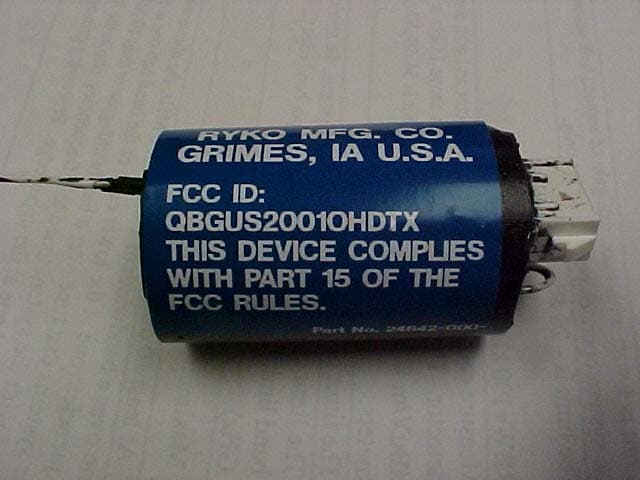
Click to zoom
Application Details
- Equipment Class
- DSC - Part 15 Security/Remote Control Transmitter
- Date of Grant
- Aug 13, 2002
- Application Purpose
- Original Equipment
- Date of Application
- Aug 13, 2002
- Equipment Note
- Safety Device for Carwash
- Frequency Range
- 418.00000000 - 418.00000000
- Company
- Ryko Mfg. Company
- Country
- United States
Documents & Files
Document Text
Text extracted from the exhibit documents filed with the FCC. Open a document above to read the original.
Users Manual
3 Item #4. I do not know why you did not receive the owner’s manual information. The information below is the exact text of what is printed in the Owner’s Manual for the machine in which the transmitter is installed. As one can see, there is no user interaction. The transmitter is installed and it operates. It is only being used as a safety device which should be used only on very rare occasions. The entire manual is not printed below. Since the actual manual (hundreds of pages) is for a very large and complex machine, only the pertinent section is excerpted for your needs. OPTIONAL SPRAY ARM BREAK AWAY The optional Spray Arm Break Away system allows the UltraSonic 2001-Overhead machine to shut down in the event that a customer drives their vehicle into the spray arm when it is in front of or behind the vehicle. To prevent damage if this occurs, a shear bolt in the spray arm mechanism breaks to prevent damage to the vehicle or the wash equipment. When this happens a tilt switch activates a small radio transmitter that is mounted on the spray arm. A radio receiver mounted in the machine gantry terminal box signals the machine controls causing the machine to immediately shut down and no longer operate. The machine is in a no-operation condition and can no longer arm for a wash. It remains in this state until it is reset. The machine's 2-digit display will show an 08 diagnostic code and a 4-digit diagnostic code 8608 will be recorded. The bay switch buzzer will sound for 5 seconds and the machine movement beeper alarm will sound continuously. RETURNING THE MACHINE TO OPERATION STEP 1: Inspect the spray arm for safe continued operation. STEP 2: Remove the white screw caps from the heads of the four (4) screws that secure the white plastic cover to the horizontal spray arm. Remove the plastic cover and the mounting clamp with transmitter off of the spray arm by removing the four (4) screws. Note: The transmitter assembly will still be connected to the tilt switch and should be kept near enough to the spray arm to prevent interfering with this connection. STEP 3: Remove and save the existing flat 3/8” (10 mm) washer and nut from the broken shear bolt. Install the new shear bolt into the spray arm where the broken bolt was removed. CAUTION! USE ONLY THE SHEAR BOLT RECOMMENDED FOR THIS EQUIPMENT. USE OF ANOTHER BOLT WILL NOT ALLOW THE SPRAY ARM BREAK AWAY TO OPERATE PROPERLY AND MAY CASUE DAMAGE TO THE MACHINE OR TO VEHICLES. WHEN ORDERING REPLACEMENT PARTS, CONTACT THE RYKO PARTS DEPARTMENT IF UNSURE OF THE PROPER PART TO ORDER,. Install the flat 3/8” (10 mm) stainless steel washer under the nut when replacing a broken shear bolt. Do not install the washer under the head of the shear bolt . Draw the two stainless steel blocks (where the bolt goes through) of the break-away assembly together by tightening the nut. After drawing the two halves together, loosen the nut until the washer under the nut can spin freely (approximately 1/4 turn). STEP 4: Reassemble the white plastic cover and the mounting clamp with transmitter onto the horizontal spray arm using the four (4) screws previously removed. Reattach the four (4) screw caps previously removed. Refer to the Top Spray Arch Cover Installation drawing in the Installation Manual. 4 WARNING! NEVER RESET THE MACHINE TO ALLOW FURTHER OPERATION WITHOUT FIRST REPLACING THE SHEAR BOLT AND INSPECTING THE SPRAY ARM AND MACHINE FOR CONTINUED SAFE OPERATION. FAILING TO DO SO MAY RESULT IN DAMAGE TO THE MACHINE OR A VEHICLE. IF IN DOUBT, CONTACT RYKO CUSTOMER SERVICE FOR ASSISTANCE. STEP 5: The machine will not operate again until it is reset via the Test Function FC “Arm Break Away Reset”. Refer to the Test Function Information document included in the Owner’s Manual to reset the machine movement beeper alarm and allow the machine to operate normally. Spray Arm Break away Radio Transmitter information : This equipment complies with part 15 of the FCC Rules. Any changes or modifications not expressly approved by the manufacturer could void the user’s authority to operate the equipment. FCC ID. QBGUS2001OHDTX This device complies with Part 15 of the FSS Rules. Operation is subject to the following two conditions: (1) this device may not cause harmful interference, and (2) this device must accept any interference received, including interference that may cause undesired operation. Roger E. Bocox Roger E. Bocox Product Engineering Manager, Electronics and Embedded Controllers Group Ryko Mfg. Co. 11600 N.W. 54th Ave., Grimes, Iowa, U.S.A. An ISO Certified Company (515) 986-3700 Ext. 156 FAX (515) 986-3621 Email: [email protected] Visit our Website at: www.ryko.com
Cover Letter(s)
American Telecommunications Certification Body Inc. 6731 Whittier Ave, McLean, VA 22101 July 10, 2002 RE: Ryko Manufacturing Company FCC ID: QBGUS2001OHDTX After a review of the submitted information, I have a few comments on the above referenced Application. 1) Please provide a FRN Number for Internet Telemetry. This is now required for all Grantees - (reference MD Docket No. 00-205). To obtain an FRN online, visit the FCC's Web site at www.fcc.gov and click the Commission Registration System (CORES) link. For further assistance, please either refer to the FAQ at this same link; contact the CORES helpdesk at [email protected]; or call the CORES helpdesk toll-free number: 1-877-480-3201. 2) Please provide a clearer photograph of the bottom of the PWB (internal photograph). 3) FYI. Since the RF output power of devices falling under 15.231 are so low, the FCC does not require RF exposure exhibits for these types of devices. Therefore, any RF exposure information will not be reviewed. 4) Please note that the phrase "FCC ID: QBGUS2001OHDTX" must be contained on a single line. Please provide a corrected labeling exhibit (CFR 2.925(a)(1)). 5) Since the EUT contains a modular component for the TX circuitry, please provide a parts list that shows this part from an OEM manufacturer. If necessary, please update the confidentiality letter. 6) The following exhibits are currently missing: Operational Description, Test Report, Users Manaul, and Test Setup Photos. Timothy R. Johnson Examining Engineer mailto: [email protected] The items indicated above must be submitted before processing can continue on the above referenced application. Failure to provide the requested information may result in application termination. Correspondence should be considered part of the permanent submission and may be viewed from the Internet after a Grant of Equipment Authorization is issued. Please do not respond to this correspondence using the email reply button. In order for your response to be processed expeditiously, you must submit your documents through the AmericanTCB.com website. Also, please note that partial responses increase processing time and should not be submitted. Any questions about the content of this correspondence should be directed to the sender.
Cover Letter(s)
American Telecommunications Certification Body Inc. 6731 Whittier Ave, McLean, VA 22101 July 31, 2002 RE: Ryko Manufacturing Company FCC ID: QBGUS2001OHDTX After a review of the submitted information, I have a few comments on the above referenced Application. 1) Please explain what information is encoded in the pulse train in order to show compliance with 15.231(a). 2) Information in the test report shows that the unit stops transmitting within 51 us of the switch being released. From talking with Bill Graff, it is my understanding that this device is used as a self contained fluid level sensor with RF transmitter used to transmits an alarm signal if the fluid gets low (please note that an intended functional description was not provided, nor has the users manual as of this time). Assuming this is the correct intended application, this device should be considered to be activated by an external "non-thinking" sensor (vs. hand controlled - manual) and must meet with the 5 second limitation for automatic transmissions. From our review of the application it does not appear that this design will automatically deactivate within 5 seconds as required for devices that are automatically activated. Please provide information which shows that this device meets this requirement by showing a plot over a 10 second period after the device is activated (and the mercury switch continues to remains in the triggered state). 3) FYI, for frequencies at 1254 MHz, 2090 MHz, and 2508 MHz, you could have employed the higher limit of 60.3 dBuV/m as allowed by 15.231 (a)(3). 4) The following exhibit is currently missing: Users Manual. Timothy R. Johnson Examining Engineer mailto: [email protected] The items indicated above must be submitted before processing can continue on the above referenced application. Failure to provide the requested information may result in application termination. Correspondence should be considered part of the permanent submission and may be viewed from the Internet after a Grant of Equipment Authorization is issued. Please do not respond to this correspondence using the email reply button. In order for your response to be processed expeditiously, you must submit your documents through the AmericanTCB.com website. Also, please note that partial responses increase processing time and should not be submitted. Any questions about the content of this correspondence should be directed to the sender.
Cover Letter(s)
RYKO Manufacturing Company ! 11600 N.W. 54th Ave. ! P.O. Box 38 Grimes, Iowa 50111 ! Phone (515) 986-3700 ! www.ryko.com Fax: 515-986-3621 ! [email protected] 1 To: American Telecommunications Certification Body, Inc. 6731 Whittier Ave., McLean, VA 22101 Attn: Timothy R. Johnson, Examining Engineer REF: FCC ID # QBGUS2001OHDTX Dear Sir, After reviewing your comments as to items which still need to be addressed on the application for FCC approval, I would like to address each item individually. Referencing your letter of July 31, 2002. Item #1. Encoder pulse train. As background information, this transmitter is basically the same as a garage door opener. It is a purchased module from Linx Technologies model #TXE418-KH. This is a single chip, to which you attach power, an antenna, and a code selection switching system. The code selection system, usually, in a garage door opener, is a 3 position dip switch of 10 poles. This will yield 10 3 possible code combinations. If the transmitter is activated, it sends out this code number to be matched up by a similarly programmed receiver. Page #3 of the Linx document supplied shows how the code pulse stream is produced. In our application, in lieu of putting in a DIP switch, we are tying the code selection inputs either high, low, or unconnected to select operator codes. In our particular application, we are using two different codes. This would be similar to using a multiple button garage door opener, where the large button opens the door and one of the smaller buttons turns on the light, etc. In our application, one code number activates the system when power is applied to the module, and the other code number is sent if, at the same time as the power is applied, that the small IC chip recognizes that the power supply (battery) voltage has dropped below 2.85 Volts. These signals are picked up by the receiver about 5 feet away. The first code is an alarm used to shut down the machinery, and the second code number tells the system that the battery is getting low in the transmitter and it is in need of being replaced. Our service personnel will test this system at each service call and check to see if the battery needs replacement at that time. There is no data being sent through this transmission—only the code. 2 Item #2. Intended use of the transmitter You had some questions and you explained your concept as to what the transmitter was used for. Evidently, the information you received was in error. The device does not detect fluid levels. Let me explain. This transmitter is being used as an additional backup safety device for a carwash machine. The carwash machine is the type that you see in many gas stations around the U.S. and the world. The machine is on tracks and travels forward and backward spraying water at high pressure from all angles on the vehicle. This machine accomplishes this through a robotic arm that traverses the perimeter of the vehicle at a set distance from the vehicle surface. If, for some reason, things do not operate as designed or the vehicle moves in the carwash bay unexpectedly, there is the chance that the robotic arm could contact the vehicle. To minimize damage to the vehicle, the arm is heavily padded. Still, in very rare cases, the arm could come in contact with the vehicle hard enough to break a shear pin at the pivot point on the arm. Our desire is for the machine to stop immediately and shut down, alarming to the attendant that something is not operating properly. A large Klaxon horn is provided to annunciate this condition, as well as electronic signaling to local and/or remote service personnel. When the robotic arm is spraying high pressure and high volume water on the car, the water pressure produces a moment in the spray arm in the opposite direction to that of the water spray. Therefore, the shear pin is necessary to keep the arm from moving. The transmitter system is being used, in this case, in lieu of a commutator system. Due to the large amounts of water and chemicals, etc. that are present in the area, it was determined that a commutator system to be used to signal a breakage of the shear pin was not practical. It would be nearly impossible to keep clean and operable all of the time under all conditions. For the above reason, the transmitter/ receiver system was developed. If the shear pin breaks, the relative position of the arm is noted by a tilt switch located on the rotating robotic arm assembly. This tilt switch applies power to the transmitter. The transmitter sends the proper code (see item #1 above for details). The code is received by the receiver. The receiver sends signals to the PLC that controls the carwash machine. Under this condition, the PLC shuts down the carwash machine immediately. It will not move or spray water. The service attendant is notified of the condition. Once the shear pin is broken, the force of the water pressure pushes the arm away from the vehicle and the tilt switch is activated. As soon as the PLC shuts off the water to the arm, the force of gravity is greater than the water pressure as it is reduced to zero, and the arm returns to a more normal location where the tilt switch is not activated, and the transmitter is shut off. Since we are dealing with water pressure and some mechanical systems, it is not possible to come up with an exact time that the transmitter is capable of being kept on. Depending on the installation and site water pressure, this time is somewhere between 2 and 4 seconds maximum. Item #3. This issue I do not know anything about or what you mean by this. The frequency of the device was chosen by what was available from the manufacturer of the modules. The only frequencies offered are 315Mhz, 418Mhz, and 433Mhz. We chose 418Mhz for our application for no particular reason. Since we only need to transmit about 20 feet at the most, the DbuV/m allowed appeared and tested to be more than adequate for our needs. 3 Item #4. I do not know why you did not re…
Text truncated - open the document above for the full version.
Cover Letter(s)
REOUEST FOR CONFIDENTIALITY Ryko Manufacturing Company requests confidentiality with regard to the following documents the filing for equipment approval identified by FCC ID No. QBGUS20010HDTX. Schematic diagrams of the product contained in electronic file identified as Ryko Part number 24627-000 1 It is the opinion of Ryko Manufacturing Company that disclosure of this information would result in significant loss of revenue. This information should be kept confidential for 7 years. By: Ro er E. Bocox, Engineering Product Manager, Electronics and Embedded Controllers Group Date: This 19th day of April 2002 Ryko Manufacturing Company 11600 N.W. 54th Avenue Grimes. IA 50111
Internal Photos
Photo 1 - Top of PWB with battery removed Photo 2 - Top of PWB Photo 3 - Bottom of PWB (No components)
Operational Description
Timothy, here are two assembly drawing that show the tilt switch mounted on the arm. Notice on 22136-005 View B-B that items 13 and 14 are the shear pin assembly. Notice the angles so that you can see that with the shear pin sheared, gravity will drop the arm down to an un activated position on the switch. Arm (item #1) rotates at the pivot point at the swivel (item #4). Drawing 25108-000 shows greater detail of the tilt switch (iten #14) on this drawing. Notice the connector that plugs into the transmitter. The transmitter, itself, is placed under the foam cover on the upper portion of the arm. I hope that this is enough detail for your investigation. If not, let me know. Best regards, Roger E. Bocox Product Engineering Manager, Electronics and Embedded Controllers Group Ryko Mfg. Co. 11600 N.W. 54th Ave., Grimes, Iowa, U.S.A. An ISO Certified Company (515) 986-3700 Ext. 156 FAX (515) 986-3621 Email: [email protected] Visit our Website at: www.ryko.com Roger, Thank you for the information. Regarding the "tilt-switch" and its installation, can you please provide the following information: 1) technical information regarding the type of switch used (i.e. data sheets/photographs, etc.) 2) drawings, schematics, and/or photographs, etc, that shows the basic installation of the switch and how it will be activated. Thank You, Tim Johnson To: "Timothy R. Johnson" <[email protected]> Subject: Re: FCC ID: QBGUS2001OHDTX "Timothy R. Johnson" <[email protected]> 08/07/2002 03:40 PM To: [email protected] cc: Subject: Re: FCC ID: QBGUS2001OHDTX Page 1 of 2In 8/14/2002Printed for "Timothy R. Johnson" <[email protected]> At 12:22 PM 8/6/2002, you wrote: >Attached is a .pdf document that should assist you with your >examination. Please get back to me if you need more information or any >changes. Thanks. > > > > >Best regards, > >Roger E. Bocox >Product Engineering Manager, >Electronics and Embedded Controllers Group >Ryko Mfg. Co. >11600 N.W. 54th Ave., Grimes, Iowa, U.S.A. >An ISO Certified Company >(515) 986-3700 Ext. 156 FAX (515) 986-3621 >Email: [email protected] >Visit our Website at: www.ryko.com 22136 -005-.pdf 25018-000-.pdf Page 2 of 2In 8/14/2002Printed for "Timothy R. Johnson" <[email protected]>
Operational Description
Rev. No. D Revision Note Web Site 2001 Date 1-2-01 Signature RG PART NUMBER SPECIFICATION Comus Group of Companies PRODUCT DATA SHEET SWITCHING VOLTAGE SWITCHING CURRENT SWITCHING CAPACITY CONTACT RESISTANCE DIFFERENTIAL ANGLE OPERATING TEMPERATURE (Continuous) OPERATING TEMPERATURE (Intermittent) STORAGE TEMPERATURE CASE MATERIAL FEATURES Max. Vac Max. A Max. VA Max. mΩ Max. Deg. ̊ Deg. ̊C Deg. ̊C Deg. °C 240 0.5 50 0.25 10 -20 ̊ +70 ̊ -25 ̊ +70 ̊ Blue Polystyrene Standard TILT SWITCH MODULE - Mercury Contacts TSM 10/240 Drawings not to scale All dimensions in mm (inches) nominal FORM AE043 ISS1 As part of the company policy of continued product improvement, specifications may change without notice. Our sales office will be pleased to help you with the latest information on this product range and details of our full design and manufacturing service. All products are supplied to our standard conditions of sale otherwise agreed in writing. ©2001 Copyright Comus Group of Companies These switches are filled with toxic materials and should not be opened 20.0 (.787) 2.0 (.079) 7.0 (.276) 30.0 (1.181) 16.0 (.630) 7.0 (.276) 10.0 (.394) 5.0 (.197) Fixing slots 6 x 3.3 (.130) 300.0 (11.811) 5.0 (.197) 25.0 (.984) 2 x round 0.14 2 PVC covered and insulated The Comus Group of Companies consist of: Assemtech Europe Limited E. Bachem GmbH Comus International W. Gunther GmbH Gunther Belgium Gunther France S.T.G. Manufactured in the UK This product is fully sealed to give maximum mechanical protection and minimise the ingress of dust and moisture. As a guide, the product is expected to meet the requirements of IP65. These switches operate when tilted from the horizontal position. The switch movement required to cause contact change (exam- ple off to on) is called the differential angle. It is very important when designing a tilt switch to allow for the differential angle and understand that when in the horizontal position the switch contact may be open or closed. SWITCHING VOLTAGE Unless specified switches can be used on AC and DC loads. For DC voltages reduce AC rating to 70%. Horizontal Mounting OFF ON Differential angle 5° 5° Long lead to top
Test Report
NEMKO Test Report:1L0564RUS1 Applicant:Ryko Manufacturing Company 11600 NW 54 th Ave. PO Box 38 Grimes, Iowa 50111 Equipment Under Test:24631-000 (E.U.T.)418 MHz RF Transmitter In Accordance With:FCC Part 15, Subpart C For Low Power Transmitters Operating Periodically In The Band 40.66 - 40.77 MHz And Above 70 MHz Tested By:Nemko Dallas, Inc. 802 N. Kealy Lewisville, TX 75057-3136 Authorized By: Tom Tidwell, RF Group Manager Date: Total Number of pages: Nemko Dallas, Inc. FCC PART 15, SUBPART C LOW POWER TRANSMITTERS EQUIPMENT: 24631-000 PROJECT NO.: 1L0564RUS1 Page 2 of 23 TABLE OF CONTENTS Section 1. Summary of Test Results............................................................................................ 3 Section 2. Equipment Under Test (E.U.T.).................................................................................. 5 Section 3. Equipment Configuration ........................................................................................... 8 Section 4. Transmission Requirements........................................................................................ 9 Section 5. Radiated Emissions...................................................................................................12 Section 6. Occupied Bandwidth ................................................................................................ 16 Section 7.Block Diagrams ......................................................................................................... 18 Section 8. Test Equipment List .................................................................................................21 ANNEX A - RESTRICTED BANDS............................................................................................ 22 Nemko Dallas, Inc. FCC PART 15, SUBPART C LOW POWER TRANSMITTERS EQUIPMENT: 24631-000 PROJECT NO.: 1L0564RUS1 Page 3 of 23 Section 1.Summary of Test Results Manufacturer:Ryko Manufacturing Company Model No.:24631-000 General: All measurements are traceable to national standards. These tests were conducted on a sample of the equipment for the purpose of demonstrating compliance with Part 15, Subpart C, Paragraph 15.231. All tests were conducted using measurement procedure ANSI C63.4-1992. Radiated emissions are made on an open area test site. A description of the test facility is on file with the FCC. New SubmissionProduction Unit Class II Permissive ChangePre-Production Unit THIS TEST REPORT RELATES ONLY TO THE ITEM(S) TESTED. THE FOLLOWING DEVIATIONS FROM, ADDITIONS TO, OR EXCLUSIONS FROM THE TEST SPECIFICATIONS HAVE BEEN MADE. See “ Summary of Test Data”. NVLAP LAB CODE: 100426-0 NEMKO Dallas Inc. authorizes the above named company to reproduce this report provided it is reproduced in its entirety and for use by the company’s employees only. Any use which a third party makes of this report, or any reliance on or decisions to be made based on it, are the responsibility of such third parties. NEMKO Dallas Inc. accepts no responsibility for damages, if any, suffered by any third party as a result of decisions made or actions based on this report. This report applies only to the items tested. Nemko Dallas, Inc. FCC PART 15, SUBPART C LOW POWER TRANSMITTERS EQUIPMENT: 24631-000 PROJECT NO.: 1L0564RUS1 Page 4 of 23 Summary Of Test Data Name of TestParagraph No.Results Transmission Requirements15.231(a)Complies Radiated Emissions15.231(b)Complies Occupied Bandwidth15.231(c)Complies Frequency Tolerance15.231(d)Complies Alternate Field Strength Requirements15.231(e)N/A Powerline Conducted Emissions15.207Complies Footnotes: The EUT complies with the transmission requirements of 15.231(a), therefore 15.231(e) is not applicable. Nemko Dallas, Inc. FCC PART 15, SUBPART C LOW POWER TRANSMITTERS EQUIPMENT: 24631-000 PROJECT NO.: 1L0564RUS1 Page 5 of 23 Section 2.Equipment Under Test (E.U.T.) General Equipment Information Frequency Range: 418 MHz Operating Frequency(ies) of Sample: 418 MHz Type of Emission: Pulsed Supply Power Requirement: 3 Volt Lithium battery Duty Cycle Correction Factor: -8.6 dB Nemko Dallas, Inc. FCC PART 15, SUBPART C LOW POWER TRANSMITTERS EQUIPMENT: 24631-000 PROJECT NO.: 1L0564RUS1 Page 6 of 23 Description of E.U.T. The EUT is a simple code transmitter based on an off-the-shelf Encoder/Decoder chip set. The transmitter transmits a unique identifying code. Modifications Incorporated in E.U.T. To achieve compliance the following change was made: a T network (Voltage divider ) was added at input to antenna to reduce power output of the carrier. Nemko Dallas, Inc. FCC PART 15, SUBPART C LOW POWER TRANSMITTERS EQUIPMENT: 24631-000 PROJECT NO.: 1L0564RUS1 Page 7 of 23 Justification The E.U.T. was configured for testing as per typical installation. The following combinations were investigated to establish worst case configuration: (1) Mounted upright (2) Lying flat Exercise Mode The E.U.T. exercise mode used during radiated and conducted testing was designed to exercise the various system components in a manner similar to typical use. Exercise mode: (1) Continuous transmit Nemko Dallas, Inc. FCC PART 15, SUBPART C LOW POWER TRANSMITTERS EQUIPMENT: 24631-000 PROJECT NO.: 1L0564RUS1 Page 8 of 23 Section 3.Equipment Configuration Equipment Configuration List: ItemDescriptionModel No.Serial.Rev . (A)Transmitter24631-000None (B)Mercury switchUnknownNone (C) (D) (E) (F) (G) Inter-connection Cables: There are no detachable cables. Configuration of the Equipment Under Test (E.U.T) Nemko Dallas, Inc. FCC PART 15, SUBPART C LOW POWER TRANSMITTERS EQUIPMENT: 24631-000 PROJECT NO.: 1L0564RUS1 Page 9 of 23 Section 4.Transmission Requirements NAME OF TEST: Transmission RequirementsPARA. NO.: 15.231(a) TESTED BY: David LightDATE: 1/16/2002 Minimum Standard: 15.231(a) Continuous transmissions such as voice, video or data transmissions are not permitted. 15.231(a)(1) A manually operated transmitter shall employ a switch that will automatically deactivate the transmitter within…
Text truncated - open the document above for the full version.
Contact Information
Applicant
Roger Bocox(Engineering Product Manager)
Technical Contact
Nemko Dallas IncTom Tidwell
[email protected]972-436-9600
802 N Kealy · Lewisville, Texas · United States
Non-Technical Contact
Nemko Dallas IncDenise Godfrey
[email protected]972-436-9600
Test Firm
Nemko Dallas, Inc.Michael Cantwell
Technical Specifications
| # | Rule Parts | Frequency Range | Power Output |
|---|---|---|---|
| 1 | 15.231 | 418 MHz - 418 MHz | - |