QBZ627TRemote Transmitter type TX4A
JMG Systems Ltd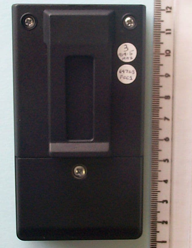
Click to zoom
Application Details
- Equipment Class
- DSR - Part 15 Remote Control/Security Device Transceiver
- Date of Grant
- May 19, 2002
- Application Purpose
- Original Equipment
- Date of Application
- May 16, 2002
- Equipment Note
- Remote Transmitter type TX4A
- Frequency Range
- 914.27900000 - 914.81000000
- Company
- JMG Systems Ltd
- Country
- United Kingdom
Documents & Files
Document Text
Text extracted from the exhibit documents filed with the FCC. Open a document above to read the original.
Users Manual
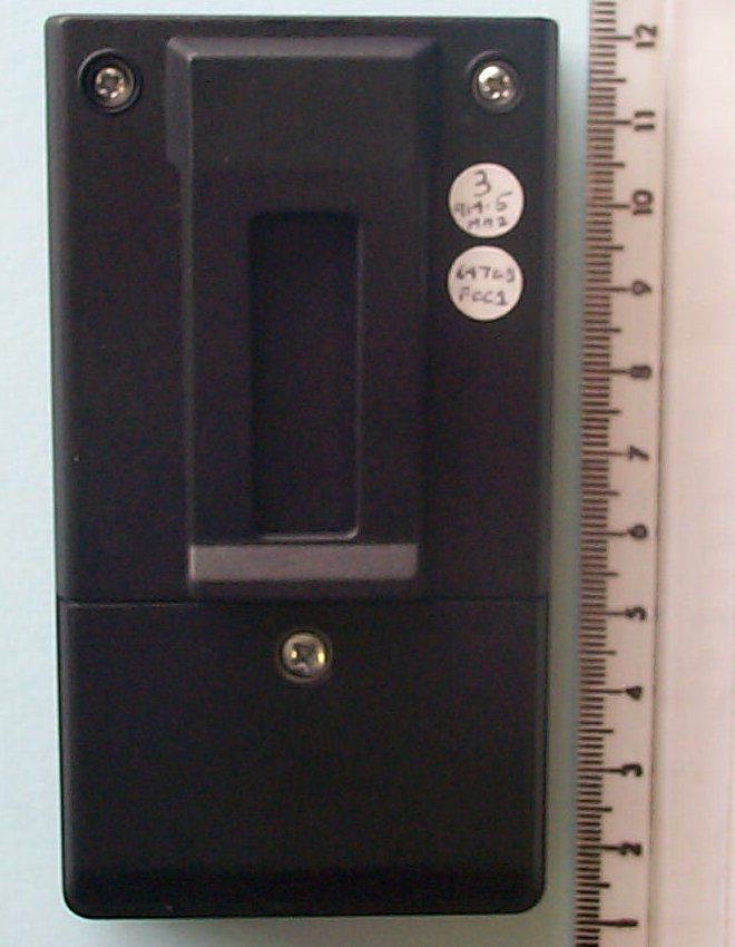
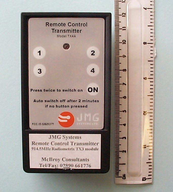
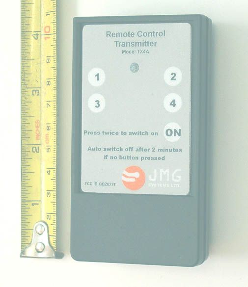
JMG Systems Ltd 68A Derry Road, Omagh, Co. Tyrone, N. Ireland, BT78 5ED Tel:+44 (0)28 8224 4131 Fax:+44 (0)28 8225 2686 e-mail:[email protected] USER MANUAL FOR REMOTE CONTROL TRANSMITTER Model TX4A JMG TX user manual.DOCPage 1 of 211 May 2002 FCC Compliance FCC ID: QBZ627T This device complies with Part 15 of the FCC Rules. Operation is subject to the following two conditions: (1) this device may not cause harmful interference, and (2) this device must accept any interference received, including interference that may cause undesired operation. CAUTION:Changes or modifications not expressly approved by JMG Systems Limited could void the user's authority to operate this equipment. General Description The Model TX4A Remote Control Transmitter is a small, handheld, battery powered, 914.5MHz radio transmitter unit which permits the remote control of four separate auxiliary functions in quarry and other heavy machinery. Front and rear views of the Model TX4A Remote Control Transmitter are shown in the photographs on the right and below. There are 5 operating buttons, labelled 1, 2, 3, 4, ON, and an LED (light emitting diode) indicator on the front face of the unit. Buttons 1 to 4 are transmit buttons. A special feature of the Model TX4A is the ON safety button. The purpose of the ON button and the 2 minute timeout sequence is to minimise the risk of accidental transmissions when, e.g., the unit is being carried in the user's pocket. The rear face of the unit is fitted with a belt clip and the battery compartment lid. Safety THIS UNIT MUST ONLY BE OPERATED BY AUTHORISED PERSONNEL. THE SAFETY PROCEDURES RELEVANT TO THE MACHINERY BEING CONTROLLED MUST BE OBSERVED. PRIOR TO EACH TRANSMISSION THE OPERATOR MUST HAVE CLEAR VISUAL SIGHT OF THE ITEM TO BE CONTROLLED. Operation Press the ON button twice to enable the transmit buttons. (Note - The interval between the two presses must be less than 2 seconds). The LED will flash once to indicate that the transmit buttons are active. If no transmit button is pressed during an ON period of 2 minutes (approximately), the transmit buttons are automatically inhibited. Pressing a transmit button restarts the 2 minute timeout. The LED repetitively flashes whilst a transmit button is pressed JMG Systems Ltd 68A Derry Road, Omagh, Co. Tyrone, N. Ireland, BT78 5ED Tel:+44 (0)28 8224 4131 Fax:+44 (0)28 8225 2686 e-mail:[email protected] USER MANUAL FOR REMOTE CONTROL TRANSMITTER Model TX4A JMG TX user manual.DOCPage 2 of 211 May 2002 Batteries The unit is powered by two 1.5 volt AAA size Alkaline batteries. With normal usage, the batteries would be expected to last in excess of 8 months. The brightness of the LED whilst transmitting provides an indication as to the state of the batteries. If the LED appears very dim, the batteries should be replaced. To replace the batteries:- 1 Undo the 3mm screw securing the battery compartment lid. 2 Remove the lid by raising at the end adjacent to the belt clip. 3 Remove the exhausted batteries. 4 Fit two new AAA size Alkaline batteries taking special care to ensure that the battery + polarity symbols align with the + marks embossed in the base of the battery compartment. 5 Refit lid by engaging the small catches at the bottom edge of the lid with the slots on the lower edge of the battery compartment and then fold the lid towards the belt clip. Insert 3mm screw and secure. Warranty JMG Systems warrants that this instrument will be free from defects and faulty workmanship for a period of one year from date of first purchase. JMG Systems sole responsibility and buyer’s exclusive remedy shall be the repair, or if we deem it necessary, the replacement of all or part thereof at JMG Systems option. This warranty does not cover any faults or defects caused by accident, misuse, fair wear and tear, neglect, tampering with the equipment, or any attempt at adjustment or repair other than by JMG Systems. In no event shall JMG Systems, or its agents or distributors, be liable for any direct, indirect, incidental or consequential damages arising out of customer’s purchase or use of this product, even if JMG Systems has advance notice of the possibility of such damage. Defective products should be returned, freight prepaid, with a full description of the defect to your supplier or JMG Systems at the address below. JMG Systems Ltd 68A Derry Road, Omagh, Co. Tyrone, UK BT78 5ED
Cover Letter(s)
TRL 51F050 iss01 Request for Confidentiality 30 April 2002 TRL Compliance Services Ltd Long Green Forthampton Gloucester GL19 4QH UK RE: Certification Application FCC ID:QBZ627T To Whom It May Concern: Please be advised that the following information is to be held confidential on behalf of JMG Systems Ltd • Technical Description • Block Diagram • Schematics The application contains technical information which JMG Systems Ltd deems to be trade secrets and propriety. If made public, the information might be used to the disadvantage of the applicant in the market place. Thank you for your attention to this matter. Yours faithfully JMG Systems Ltd Joe McGoldrick
ID Label/Location Info
50.0 72.0 Remote Control Transmitter Model TX4A ON Press twice to switch on Auto switch off after 2 minutes if no button pressed FCC ID: QBZ627T 2 4 3 1 9.0 16.0 16.0 9.0 19.0 3.0 12.0 12.0 26.0 22.0 Ø 8.0 Ø 3.0 NOTES: Material: 0.3mm thick Vinyl with double sided high bond strength backing adhesive. Colours: Background: JMG grey Button circles: White (no line) Text: Black DECAL DRAWINGS REMOTE CONTROL TRANSMITTER Model TX4A FCC ID: QBZ627T 5 May 2002 50.0 72.0 Microsoft San Serif Size 10 Bold Microsoft San Serif Size 7 Bold Microsoft San Serif Size 14 Bold for buttons 1, 2, 3, & 4. Size 11 Bold for ON button Microsoft San Serif Size 9 Bold Microsoft San Serif Size 6 Bold JMG Systems Logo DECAL ARTWORK FCC ID DECAL DIMENSIONS SYSTEMS LTD. JMG Systems Ltd 68A Derry Road, Omagh, Co. Tyrone, N. Ireland, UK. BT78 5ED Tel: +44 (0)28 8224 4131 Fax: +44 (0)28 8225 2686 e-mail: [email protected] COMPLIANCE STATEMENT As their is no suitable position for a label on the small transmitter unit the compliance statement will be shown, as below, in the User's Manual. FCC ID: QBZ627T This device complies with Part 15 of the FCC Rules. Operation is subject to the following two conditions: (1) this device may not cause harmful interference, and (2) this device must accept any interference received, including interference that may cause undesired operation.
ID Label/Location Info
TRL 51F046 iss01 FCC Labelling Requirements and Information 05 May 2002 TRL Compliance Services Ltd Long Green Forthampton Gloucester GL19 4QH UK RE: FCC Labelling Requirements FCC ID:QBZ627T The following label information is required by the FCC Rules and Regulations for certified devices. Also attached, please find marketing information required by the FCC Rules and Regulations. Thank you for your attention to these matters. Yours faithfully JMG Systems Ltd Joe McGoldrick
Parts List/Tune Up Info
JMG Systems Ltd 68A Derry Road, Omagh, Co. Tyrone, N. Ireland, BT78 5ED Tel:+44 (0)28 8224 4131 Fax:+44 (0)28 8225 2686 e-mail:[email protected] 14 May 2002 Parts List Model TX4A Radio Remote Control Transmitter PCB ITEMS LIST ITEMDESCRIPTION/REF.VALUE/TYPESUPPLIERSUPPLIERS CODENo. OFF 1R41K 0.125WRadiospares144-2451 2R5,R610K 0.125WRadiospares144-3682 3C2100nFRadiospares264-49111 4C147uFRadiospares166-82751 5X1 4.00MHz Resonator ModuleCST4.00MGWFarnell295-3461 6IC224AA00-/PRutronik24AA00-/P1 7IC3PIC16LF627-04/PRutronikPIC16LF627-04/P1 8 TX3 Module US 914.5MHzTX3-US-F Radiometrix TX3-US-F1 9 SW1,2,3,4, & 53ETL995 (9.5mm) Farnell 674-7955 10 LD13mm LED Red Farnell322-544 1 11DIL socket - ultra low profile8 pinRadiospares 226-3821 1 12DIL socket - ultra low profile18 pinRadiospares 226-3859 1 13PCBJMG_TX03Minnitron JMG_TX03 1 OVERALL ASSEMBLY ITEMS LIST ITEMDESCRIPTION/REF.VALUE/TYPESUPPLIERSUPPLIERS CODENo. OFF 14 Assembled PCBJMG_TX03 JMG Systems JMG_TX031 15EnclosureDatec Pocket Box size MOKW A 90 71 109 1 16Pocket ClipPocket ClipOKW A 91 72 109 1 17Battery clipsSet of AAA size clipsOKW A 91 90 002 1 18PCB mounting screws2.5 x 6mmOKW A 03 05 031 4 19DecalSignal SignsTX4A Decal1 20Alkaline battery 1.5VAAACPCBT000902
Test Report
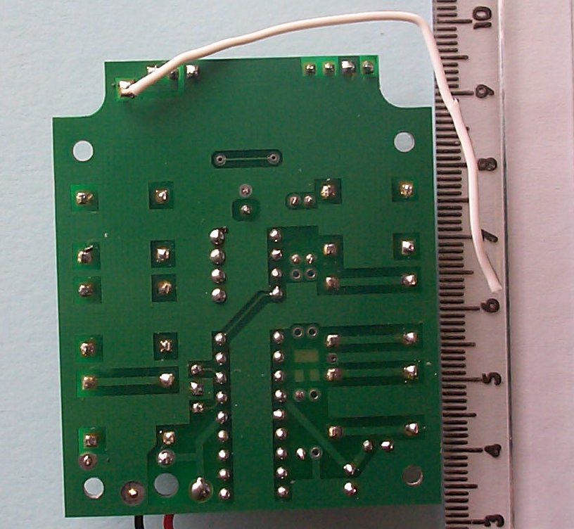
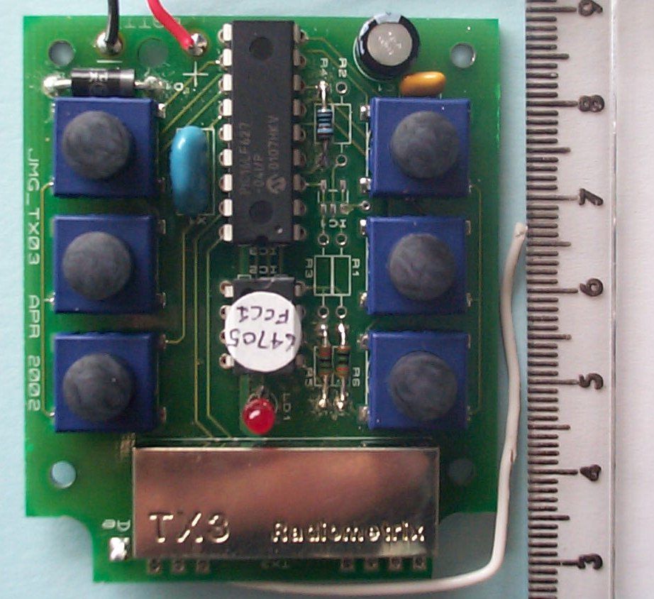
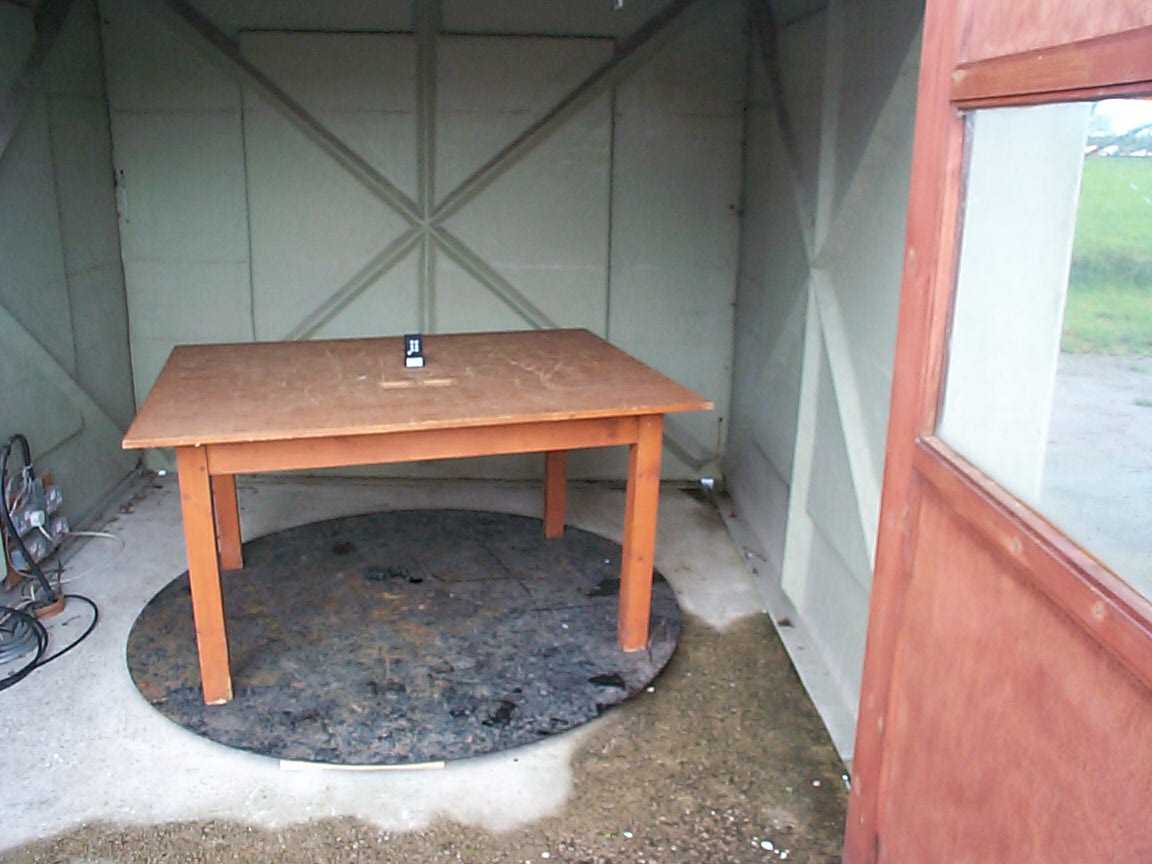
TRL C OMPLIANCE S ERVICES L TD EMC DIVISION LONG GREEN FORTHAMPTON GLOUCESTER GL19 4QH UNITED KINGDOM TELEPHONE +44 (0)1684 833818 FAX +44 (0)1684 833858 E- MAIL [email protected] www.trlcompliance.com 0728 TEST REPORT NO:RU1015/3762 COPY NO: See below ISSUE NO:1 FCC ID:QBZ627T REPORT ON THE CERTIFICATION TESTING OF A JMG SYSTEMS Ltd. TX4A REMOTE CONTROL TRANSMITTER WITH RESPECT TO THE FCC RULES CFR 47, PART 15.249 INTENTIONAL RADIATOR SPECIFICATION TEST DATE: 30 th APRIL 2002 TESTED BY:J CHARTERS APPROVED BY:PETER GREEN PRINCIPAL ENGINEER DATE:17 th May 2002 Distribution: Copy Nos:1.JMG SYSTEMS Ltd. 2.FCC EVALUATION LABORATORIES 3.TRL EMC THIS DOCUMENT MAY BE REPRODUCED ONLY IN ITS ENTIRETY AND WITHOUT CHANGE RF335 iss01RU1015/3762Page 2 of 19 CONTENTS PAGE CERTIFICATE OF CONFORMITY & COMPLIANCE3 APPLICANT’S SUMMARY4 EQUIPMENT TEST CONDITIONS5 TESTS REQUIRED6 SAMPLE CALCULATIONS6 TEST RESULTS7-8 ANNEX PHOTOGRAPHSA PHOTOGRAPH No. 1: Test setup PHOTOGRAPH No. 2: Transmitter front view PHOTOGRAPH No. 3: Transmitter rear view PHOTOGRAPH No. 4: Transmitter PCB track side PHOTOGRAPH No. 5: Transmitter PCB component side APPLICANT’S SUBMISSION OF DOCUMENTATION LISTB BAND OCCUPANCY PLOTC Notes: 1.Component failure during testYES NO [ ] [X] 2.If Yes, details of failure: 3.The facilities used for the testing of the product contain in this report are FCC Listed. 4.The contents of the attached applicants declarations and other supplied information are not covered by the scope of this laboratory’s UKAS or FCC accreditations’ and is provided in good faith. RF335 iss01RU1015/3762Page 3 of 19 CERTIFICATE OF CONFORMITY & COMPLIANCE FCC IDENTITY:QBZ627T PURPOSE OF TEST:Certification TEST SPECIFICATION:FCC RULES CFR 47, Part 15.249 TEST RESULT:Compliant to Specification EQUIPMENT UNDER TEST:TX4A REMOTE CONTROL TRANSMITTER EQUIPMENT SERIAL No:3 ITU: EMISSION CODE:61K0F1D EQUIPMENT TYPE:Remote control transmitter PRODUCT USE:Telecommand of outdoor vehicles CARRIER EMISSION: 13000μV/m ANTENNA TYPE:Integral ALTERNATIVE ANTENNA:None BAND OF OPERATION:902MHz – 928MHz CHANNEL SPACING:Wideband NUMBER OF CHANNELS:1 FREQUENCY GENERATION:SAW Resonator[ ]Crystal[X]Synthesiser [ ] MODULATION METHOD:Amplitude[ ]Digital[X]Angle [ ] POWER SOURCE(s):+3Vdc (integral battery power only) TEST DATE(s):30 th APRIL 2002 ORDER No(s):992 APPLICANT:JMG SYSTEMS Ltd. ADDRESS:68a Derry Road Omagh Co Tyrone BT78 5ED Northern Ireland TESTED BY:J CHARTERS APPROVED BY:P GREEN PRINCIPAL ENGINEER RF335 iss01RU1015/3762Page 4 of 19 APPLICANT’S SUMMARY EQUIPMENT UNDER TEST (EUT):TX4A REMOTE CONTROL TRANSMITTER EQUIPMENT TYPE:Remote control transmitter SERIAL NUMBER OF EUT:3 PURPOSE OF TEST:Certification TEST SPECIFICATION(s):FCC RULES CFR 47, Part 15.249 TEST RESULT:COMPLIANTYes No [X] [ ]. APPLICANT’S CATEGORY:MANUFACTURER IMPORTER DISTRIBUTOR TEST HOUSE AGENT [X] [ ] [ ] [ ] [ ] APPLICANT’S ORDER No(s):992 APPLICANT’S CONTACT PERSON(s):Mr Joe McGoldrick E-mail address: [email protected] APPLICANT:JMG SYSTEMS Ltd. ADDRESS:68a Derry Road Omagh Co Tyrone BT78 5ED Northern Ireland TEL:028 8224 4131 FAX:028 8225 2686 EUT(s) COUNTRY OF ORIGIN:United Kingdom TEST LABORATORY:TRL EMC UKAS ACCREDITATION No:0728 TEST DATE(s)30 th APRIL 2002 TEST REPORT No:RU1015/3762 RF335 iss01RU1015/3762Page 5 of 19 EQUIPMENT TEST / EXAMINATIONS REQUIRED 1. TEST/EXAMINATIONRULE PARTDETECTORAPPLICABILITY Intentional Emission Frequency:15.249Quasi peakYes Intentional Emission Field Strength:15.249Quasi peakYes Intentional Emission Band Occupancy:Supplied for informationYes Intentional Emission ERP (mW):No Spurious Emissions – Conducted:15.207No Spurious Emissions – Radiated <1000MHz:15.209Quasi peakYes Spurious Emissions – Radiated >1000MHz: 15.209 & 15.249 PeakYes Maximum Frequency of Search:15.33Yes Antenna Arrangements Integral:15.203Yes Antenna Arrangements External Connector:15.204No Restricted Bands15.205Yes Extrapolation Factor15.31(f)Yes 2.Product Use:Telecommand of outdoor vehicles 3.Emission Designator:61K0F1D 4.Duty Cycle:33%During operation 5.Transmitter bit or pulse rate and level:1000Bps 6.Temperatures:Ambient (Tnom)11 o C 7.Supply Voltages:Vnom+3Vdc Note: Vnom voltages are as stated above unless otherwise shown on the test report page Single channel[X] Two channel[ ] 8.Equipment Category: Multi-channel[ ] Narrowband[ ] Wideband[X] 9.Channel spacing: RF335 iss01RU1015/3762Page 6 of 19 TRANSMITTER TESTS TRANSMITTER SPURIOUS EMISSIONS – RADIATED – PART 15.209 & 15.249 Ambient temperature=11 o C(<1GHz)19 o C(>1GHz)3m measurements <1GHz[X] Relative humidity=60% (<1GHz)60% (>1GHz)0.3m measurements >1GHz[X] Conditions=Open Area Test Site (OATS)3m extrapolated from 1m[ ] Supply voltage=+3Vdc3m extrapolated from 0.3m[X] Channel number=1 FREQ. (MHz) MEAS. Rx. (dBμV) CABLE LOSS (dB) ANT FACTOR FIELD STRENGTH (dBμV/m) EXTRAP. FACTOR (dB) FIELD STRENGTH (μV/m) 30MHz- 88MHz 88MHz-216MHz 216MHz-960MHz 960MHz-1GHz 1GHz-10GHz 1829.0 2734.5 3658.0 4572.5 5487.0 30.94 22.92 23.49 24.59 16.97 0.2 0.3 0.4 0.4 0.5 26.7 30.0 32.0 32.8 34.6 57.84 53.22 55.89 57.79 52.07 20 20 20 20 20 78.0 45.8 62.3 77.5 40.1 1.705MHz to 30MHz 30μV/m@ 30m 30MHz to 88MHz100μV/m@ 3m 88MHz to 216MHz150μV/m@ 3m 216MHz to 960MHz200μV/m@ 3m 960MHz to 1GHz500μV/m@ 3m Limits 1GHz to 10GHz500μV/m@ 3m Notes: 1Results quoted are extrapolated as indicated 2Emissions were searched to: 10GHz inclusive, as per Part 15.33a 3Extrapolation factor 20dB from 0.3m to 3m, as per Part 15.31f 4Measurements >1GHz @ 1m as per Part 15.31f(1) 5Receiver detector >1GHz = CISPR, Quasi-Peak, 120kHz bandwidth 6Receiver detector >1GHz = Peak Hold, 1MHz resolution bandwidth. 7New batteries used for battery powered products. 8Only emissions within 20dBs of respective limit line are included above Test Method: 1As per Radio – Noise Emissions, ANSI C63.4: 1992 2Measuring distances as Notes 1 to 4 above 3EUT 0.8 metre above ground plane 4Emissions maximised by rotation of EUT, on an automatic turntable. Raising and lowerin…
Text truncated - open the document above for the full version.
Contact Information
Applicant
Joe McGoldrick(Mr)
Technical Contact
JMG Systems LtdJoe McGoldrick
[email protected]44 2882244131
68A Derry Road · Co Tyrone · United Kingdom
Test Firm
TRL EMC LimitedNeil Roche
Technical Specifications
| # | Rule Parts | Frequency Range | Power Output | Emission | Tolerance |
|---|---|---|---|---|---|
| 1 | 15C | 914.279 MHz - 914.81 MHz | 562.00 µW | 61K0F1D | 25000.0000000000 Hz |