QC5-09-MSS1Verics TX Module
Telemics, Inc.
Click to zoom
Application Details
- Equipment Class
- DSS - Part 15 Spread Spectrum Transmitter
- Date of Grant
- Oct 29, 2002
- Application Purpose
- Original Equipment
- Date of Application
- Oct 29, 2002
- Equipment Note
- Verics TX Module
- Frequency Range
- 902.25000000 - 927.25000000
- Company
- Telemics, Inc.
- Country
- United States
Documents & Files
Document Text
Text extracted from the exhibit documents filed with the FCC. Open a document above to read the original.
Users Manual
100-0002 Verics Module Manual v0.3 © 2002 Telemics, Inc. All Rights Reserved pg 1 - 100-0002 Verics RF Module User’s Manual Version 0.3 111 W. Washington St. Louisville, KY 40202 (502) 583-6480 www.telemics.com Copyright Information Copyright © 2000 Telemics, Inc. All rights reserved. The information contained in this manual and the accompanying software programs are copyrighted and all rights are reserved by Telemics, Inc. Telemics, Inc. reserves the right to make periodic modifications of this product without obligation to notify any person or entity of such revision. Copying, duplicating, selling, or otherwise distributing any part of this product without the prior consent of an authorized representative of Telemics is prohibited. All brands and product names in this publication are registered trademarks or trademarks of their respective holders. This material is preliminary Information furnished by Telemics in this specification is believed to be accurate. Devices sold by Telemics are covered by the warranty and patent indemnification provisions appearing in its Terms of Sale only. Telemics makes no warranty, express, statutory, and implied or by description, regarding the information set forth herein. Telemics reserves the right to change specifications at any time and without notice. Telemics’ products are intended for use in normal commercial applications. DOCUMENT INFORMATION Revision Description Version 0.2 10/14/2002–Preliminary Release Version Version 0.3 11/04/2002–Preliminary Release Version 100-0002 Verics Module Manual v0.3 © 2002 Telemics, Inc. All Rights Reserved pg 2 FCC INFORMATION Agency Identification Numbers US FCC ID: QC5-09-MSS1 CAN IC ID: 4425A-09-MSS1 Note: The product approvals above are with antennas specified below. FCC Notice WARNING: This device complies with Part 15 of the FCC Rules. Operation is subject to the following two conditions: (1) This device may not cause harmful interference, and (2) This device must accept any interference received, including interference that may cause undesired operation. Labeling Requirements WARNING: The Original Equipment Manufacturer (OEM) must ensure that FCC labeling requirements are met. This includes a clearly visible label on the outside of the OEM enclosure specifying "Contains Transmitter Module, FCC ID: QC5-09-MSS1” as well as the applicable FCC labeling as required in Part 15 of the FCC regulations. Antenna Warning WARNING: This device has been tested for FCC compliance with the antennae listed below. When the Verics RF module is integrated in the OEM product, the selected antenna should be installed in such a manner that prevents replacement with a non-approved antenna. Use of a non-approved antenna is not allowed under FCC regulations. Approved Antenna List Telemics 910-0002, Integral ¼ wave monopole, 1dBi gain Astron AXHPRAMMPTL6I, ½ wave dipole, 2dBi gain RF Exposure WARNING: The 100-0002 Verics Module is approved for mobile and base station applications per FCC Section 2.1091. To satisfy FCC RF exposure requirements, the 100-0002 must be installed with one of the antennas specified in the table above and with a separation distance of 20cm or more should be maintained between the antenna of this device and persons during operation. To ensure compliance, operations at less than this distance is not allowed. If the OEM integrates this module into a portable device as classified per FCC Section 2.1093, the OEM is responsible for obtaining a separate authorization for the final product. This device and its antenna must not be co-located or operating in conjunction with any other antenna or transmitter". The preceding statement must be included as a CAUTION statement in manuals for OEM products to alert users on FCC RF Exposure compliance. 1. 1. Overview The 100-0002 is a wireless RF transceiver implementing the Telemics’s Verics network technology. It is designed for operation under FCC part 15.247 regulations for the 902-928MHz ISM band. The 100-0002 is a frequency hopping spread spectrum transceiver providing asynchronous TTL level serial interface for communications. All aspects of Verics network operations, including frequency hopping, synchronization, neighbor discovery, and RF system data transmission/reception is performed by the module.This document includes the theory of operation, specifications, interface definition, configuration information and mechanical drawing. The OEM is responsible for ensuring the final product meets all FCC and/or appropriate regulatory agency requirements before selling any product.
Cover Letter(s)
October 28, 2002 To: American Telecommunications Certification Body Inc. 6731 Whittier Ave, McLean, VA 22101 RE: Telemics Inc. FCC ID: QC5-09-MSS1 Tim, Below you will find replies to your questions / comments. Please let me know if anything is unclear or you have any additional concerns. David Waitt (Independent Consultant for Telemics Inc.) 1) Please provide photographs of each antenna listed in this application. Photos of the two antennas have been uploaded to the ATCB website 2) Please provide a block diagram for the TX portion of the device. An RF block diagram has been uploaded to the ATCB web site 3) Devices that are modularly approved must meet the non-standard connector requirement (reference FCC da001407). Devices are typically approved as a module so that they may be sold to other companies desiring to integrate them or use them in other devices. Since Telemics Inc. can not control how the device is used or sold by other integrators, the FCC specifies that the device must incorporate non-standard connectors. Please confirm if you still desire to approve the device as a module, or provide information regarding what nonstandard connector will be utilized in the device with the Omni-directional antenna. This being the case, Telemics has elected NOT to certify the module for use with the antenna in question. References to this antenna have been removed from the certification application documentation. 4) Please provide close up Internal and External photographs of the device. Photos of the device have been uploaded to the ATCB website 5) The phrase "This device contains Transmitter module FCC ID: QC5-09-MSS1" for the outside of any product the device is installed within should be contained on a single line. Please provide an updated label. A new label drawing has been uploaded to the ATCB website 6) The FCC warning statements on the label placed external to the end product must match exactly as specified in 15.19. Please provide an updated label A new label drawing has been uploaded to the ATCB website 7) Please provide a photograph or drawing showing label placement on the device. Detailed photos of the device showing label placement has been uploaded to the ATCB website Telemics Inc. 111 W. Washington Street Suite 300 Louisville, KY 40202 8) The theory of operation states that the time slot is variable. Please explain if this is a single variable setting, or if the packet length is variable during "on the fly". If the time slots are variable "on the fly" please provide further detail on how all channels are used equally on the average. The Slot time is not variable “on the fly”. The slot time is configurable within the software, but it is not dynamic. 9) Information in the users manual regarding the gain of the dipole antenna does not match the antenna information provided. Please explain. The information in the manual was incorrect. The manual has been updated with the correct information and has been uploaded to the ATCB site. 10) The RF exposure requirements mentions a 30% duty cycle. In order to use duty cycle for general population RF exposure calculations, it must be "source-based" time-averaging based upon an inherent property or duty cycle of the device. Please either provide detailed information regarding how the duty cycle meets this requirement, or alternatively adjust the calculations assuming a duty cycle of 100% (2.1093(d)(2)). Please note that the device easily meets the 20 cm requirement at 100% duty cycle. To simplify the process, the MPE has been recalculated using a 100% duty cycle. A new MPE estimate has been uploaded to the ATCB website 11) The users manual states "To ensure compliance, operations at closer than this distance is not recommended." Since this is not classified as a portable device, this phrase should be stated as " ......distance is not allowed." The manual has been modified to incorporate this change and has been uploaded to the ATCB website 12) The RF exposure statement in the manual are missing co-location information. Specifically the following should be added "This device and its antenna must not be co-located or operating in conjunction with any other antenna or transmitter". The manual has been modified to incorporate this change and has been uploaded to the ATCB website 13) Since the device is a transceiver, when the device is in a receive mode of operation, it must meet with the Part 15 Verification requirements for a receiver (these are equivalent to the class B emissions). Please provide this data. This test has been performed and the data added to the test report. 14) Average measurements above 1 GHz must be made with a RBW = 1 MHz and VBW >= 10 Hz. The test methodology on page 19 of 43 states that the RBW was set to 1 kHz. Statement of these bandwidths in the report was an error. The measurements were performed using the correct bandwidths. 15) The test methodology for radiated spurious emission on page 18 of 43 states implies that the EUT was hopstopped, while information on page 23 stated that it constantly hopped. Please explain as this test should be performed with the device hop-stopped. The wording on the lab data is mis-leading. What they are intending to say is that the if the device “hops” 100% of the time on a given channel, it is essentially “hop-stopped”. During the test, the device was indeed transmitting at a 100% duty cycle on the channel being tested. It was not hopping. 16) Please provide information to show compliance with 15.247(g) & (h). (g) Frequency hopping spread spectrum systems are not required to employ all available hopping channels during each transmission. However, the system, consisting of both the transmitter and the receiver, must be designed to comply with all of the regulations in this section should the transmitter be presented with a continuous data (or information) stream. In addition, a system employing short transmission bursts must comply with the definition of a frequency hopping system and …
Text truncated - open the document above for the full version.
Cover Letter(s)
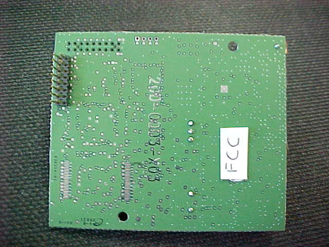
5 November 2002 To: American Telecommunications Certification Body Inc. 6731 Whittier Ave, McLean, VA 22101 RE: Telemics Inc. FCC ID: QC5-09-MSS1 Tim, Below you will find replies to your questions / comments. Please let me know if anything is unclear or you have any additional concerns. David Waitt (Independent Consultant for Telemics Inc.) 1) Please provide photographs of each antenna listed in this application that was referenced in your reply. It does not appear that we received this. The antenna photos were omitted in error. They have been uploaded at this time. 2) Please provide a photograph or drawing showing label placement on the device. A photograph was provided of the bottom of the board that had a sticker labeled "FCC", but it is not certain if this was meant for the "FCC Label". Is this were the label will be placed? The “FCC” sticker is intended to show the location of the FCC ID label. 3) Please comment on the fact that the photographs (not previously provided) appear to contain both a MMCX connector and helical antenna. The manufacturer should provide only one or the other when sold so that integrators will not simply be able to install an external antenna simultaneously with the helical antenna. The module incorporates two connectors to accommodate either antenna (Of course, for the helical, antenna, the connector is simply a “pad” on the board), however the connector to be used is selected with a 0 Ohm chip resistor. 4) The Users Manual still contains reference to the + 5 dBi gain antenna that has been removed from the application per our discussions. Please provide an updated manual. The reference to the 5dBi antenna has been removed from the manual 5) The RF exposure statement in the manual are still missing co-location information. It does not appear that these were added as specified in your reply. Specifically the following should be added "This device and its antenna must not be co-located or operating in conjunction with any other antenna or transmitter". This statement has been added to the RF exposure statement in the manual. Telemics Inc. 111 W. Washington Street Suite 300 Louisville, KY 40202 6) Additionally, the users manual should contain information as specified by 15.105(a) or (b) as appropriate. Please note that if the device is classified as Class A, a justification as to this should be provided. Since this manual is intended to address the use of the module, classification of either Class A or Class B is not applicable. The module could be incorporated into either class of host. 7) The test receiver emissions provided do not explain at what test distance most of this testing was performed at. Additionally, from looking at the data and margins, it appears that European limits may have been applied instead of Part 15 limits. Please comment. This will be clarified as soon as possible. 8) FYI, Telemics Inc. or any integrator is still responsible for re-testing the digital device/receiver emissions for each device this module is installed within even though the Transmitter does not require retesting. This is understood by Telemics and the two Telemics radios that incorporate the module have been tested and found to comply with Part 15 as a Class A device. On behalf of Telemics, Inc. David Waitt
Cover Letter(s)
American Telecommunications Certification Body Inc. 6731 Whittier Ave, McLean, VA 22101 October 18, 2002 RE: Telemics Inc. FCC ID: QC5-09-MSS1 After a review of the submitted information, I have a few comments on the above referenced Application. 1) Please provide photographs of each antenna listed in this application. 2) Please provide a block diagram for the TX portion of the device. 3) Devices that are modularly approved must meet the non-standard connector requirement (reference FCC da001407). Devices are typically approved as a module so that they may be sold to other companies desiring to integrate them or use them in other devices. Since Telemics Inc. can not control how the device is used or sold by other integrators, the FCC specifies that the device must incorporate non-standard connectors. Please confirm if you still desire to approve the device as a module, or provide information regarding what non- standard connector will be utilized in the device with the Omni-directional antenna. 4) Please provide close up Internal and External photographs of the device. 5) The phrase "This device contains Transmitter module FCC ID: QC5-09-MSS1" for the outside of any product the device is installed within should be contained on a single line. Please provide an updated label. 6) The FCC warning statements on the label placed external to the end product must match exactly as specified in 15.19. Please provide an updated label 7) Please provide a photograph or drawing showing label placement on the device. 8) The theory of operation states that the time slot is variable. Please explain if this is a single variable setting, or if the packet length is variable during "on the fly". If the time slots are variable "on the fly" please provide further detail on how all channels are used equally on the average. 9) Information in the users manual regarding the gain of the dipole antenna does not match the antenna information provided. Please explain. 10) The RF exposure requirements mentions a 30% duty cycle. In order to use duty cycle for general population RF exposure calculations, it must be "source-based" time-averaging based upon an inherent property or duty cycle of the device. Please either provide detailed information regarding how the duty cycle meets this requirement, or alternatively adjust the calculations assuming a duty cycle of 100% (2.1093(d)(2)). Please note that the device easily meets the 20 cm requirement at 100% duty cycle. 11) The users manual states "To ensure compliance, operations at closer than this distance is not recommended." Since this is not classified as a portable device, this phrase should be stated as " ......distance is not allowed." 12) The RF exposure statement in the manual are missing co-location information. Specifically the following should be added "This device and its antenna must not be co-located or operating in conjunction with any other antenna or transmitter". 13) Since the device is a transceiver, when the device is in a receive mode of operation, it must meet with the Part 15 Verification requirements for a receiver (these are equivalent to the class B emissions). Please provide this data. 14) Average measurements above 1 GHz must be made with a RBW = 1 MHz and VBW >= 10 Hz. The test methodology on page 19 of 43 states that the RBW was set to 1 kHz. 15) The test methodology for radiated spurious emission on page 18 of 43 states implies that the EUT was hop- stopped, while information on page 23 stated that it constantly hopped. Please explain as this test should be performed with the device hop-stopped. ----------------- Continued on Next Page --------------------- z Page 2October 18, 2002 16) Please provide information to show compliance with 15.247(g) & (h). 17) FYI, The antenna warning information in the users manual is oddly worded when in mentions tested to 15.203. Timothy R. Johnson Examining Engineer mailto: [email protected] The items indicated above must be submitted before processing can continue on the above referenced application. Failure to provide the requested information may result in application termination. Correspondence should be considered part of the permanent submission and may be viewed from the Internet after a Grant of Equipment Authorization is issued. Please do not respond to this correspondence using the email reply button. In order for your response to be processed expeditiously, you must submit your documents through the AmericanTCB.com website. Also, please note that partial responses increase processing time and should not be submitted. Any questions about the content of this correspondence should be directed to the sender.
Cover Letter(s)
American Telecommunications Certification Body Inc. 6731 Whittier Ave, McLean, VA 22101 November 3, 2002 RE: Telemics Inc. FCC ID: QC5-09-MSS1 After a review of the submitted information, I have a few comments on the above referenced Application. 1) Please provide photographs of each antenna listed in this application that was referenced in your reply. It does not appear that we received this. 2) Please provide a photograph or drawing showing label placement on the device. A photograph was provided of the bottom of the board that had a sticker labeled "FCC", but it is not certain if this was meant for the "FCC Label". Is this were the label will be placed? 3) Please comment on the fact that the photographs (not previously provided) appear to contain both a MMCX connector and helical antenna. The manufacturer should provide only one or the other when sold so that integrators will not simply be able to install an external antenna simultaneously with the helical antenna. 4) The Users Manual still contains reference to the + 5 dBi gain antenna that has been removed from the application per our discussions. Please provide an updated manual. 5) The RF exposure statement in the manual are still missing co-location information. It does not appear that these were added as specified in your reply. Specifically the following should be added "This device and its antenna must not be co-located or operating in conjunction with any other antenna or transmitter". 6) Additionally, the users manual should contain information as specified by 15.105(a) or (b) as appropriate. Please note that if the device is classified as Class A, a justification as to this should be provided. 7) The test receiver emissions provided do not explain at what test distance most of this testing was performed at. Additionally, from looking at the data and margins, it appears that European limits may have been applied instead of Part 15 limits. Please comment. 8) FYI, Telemics Inc. or any integrator is still responsible for re-testing the digital device/receiver emissions for each device this module is installed within even though the Transmitter does not require retesting. Timothy R. Johnson Examining Engineer mailto: [email protected] The items indicated above must be submitted before processing can continue on the above referenced application. Failure to provide the requested information may result in application termination. Correspondence should be considered part of the permanent submission and may be viewed from the Internet after a Grant of Equipment Authorization is issued. Please do not respond to this correspondence using the email reply button. In order for your response to be processed expeditiously, you must submit your documents through the AmericanTCB.com website. Also, please note that partial responses increase processing time and should not be submitted. Any questions about the content of this correspondence should be directed to the sender.
Cover Letter(s)
To: Federal Communications Commission 7435 Oakland Mills Road Columbia, Maryland 21046 Subject: Confidentiality Request for Certification Application Gentlemen, On behalf of Telemics Inc, I request that the following documents associated with the Part 15 Certification application for FCC ID: QC5-09-MSS1 be withheld from public disclosure per Section 0.459 of the FCC Rules. All circuit schematics. All electrical block diagrams All theory of operations All parts lists Hopping sequence algorithm document This request is made under the provisions of Section 0.457(d) of the FCC rules and Sections 552(b)(4) of the Freedom of information Act. These Sections authorize withholding from public inspection, materials which would be privileged as a matter of law if retained by the person submitting them in addition to materials, which would not customarily be released to the public, by that person. If you have any questions, please do not hesitate to contact me at: [email protected] or (408) 832-7053 Sincerely, David Waitt Consultant Telemics Inc. 111 W. Washington Street Suite 300 Louisville, KY 40202
Cover Letter(s)
Modular Approval Request Letter for FCC ID: QC5-09-MSS1 and Industrie Canada ID: 4435A-09-MSS1 Gentlemen, Telemics would like to request that the 900 MHz Frequency hopping product, Model 100-0002 Verics Module be certified as a module pursuant to FCC Public notice DA00-1407 to allow placement of the module into additional Telemics products in the future without pursuing a individual Certification for each product. The above-mentioned public notice outlines 8 requirements that must be met in order for the device to be considered a “module”. The table below summarizes these 8 requirements and how the Verics Module meets these requirements. DA00-1407 Module Requirement Telemics Model 100-0002 Verics Module 1: The modular transmitter must have its own shielding The Verics Module has its own RF. Refer to the pictures of the module included in this application. 2: The modular transmitter must have its own buffered modulation / data inputs The Verics Module incorporates data I/O buffering on the modulation and data inputs. This buffering is internal to the Atmel AT91R40008-66AI microprocessor of the module. 3: The modular transmitter must have its own power supply regulation The power derived from the host system that powers the RF section of the module is regulated on the Verics Module. 4: The modular transmitter must comply with the antenna connector requirements of 15.203 and 15.204( C) The Verics Module has two antenna configurations. Both meet the requirements of 15.203. One of the antennas is soldered directly to the module PCA. If that antenna is not going to be used, then an external antenna can be connected via a MMCX connector on the module PCA. Recall that the module is a professionally installed device, thus meeting the 15.203 requirements. 5: The modular transmitter must be tested in a “Stand-Alone” configuration. The transmitter cannot be installed within a “host” system during testing. The Verics Module was tested in a stand alone configuration outside of any enclosure. Refer to the test setup photos. The “Test Fixture” board in the photos is there only to provide power and the correct data I/O to the module. 6: The modular transmitter must be labeled with its own FCC ID number and if the FCC ID is not visible when the module is installed inside a host device, then the outside of the host device must be labeled as containing an internal transmitter module. The Verics Module will be clearly labeled with the FCC ID. Refer to the Regulatory drawing placement drawing. 7: The modular transmitter must comply with any specific rule or operating requirements applicable to the transmitter and the manufacturer must provide instructions along with the module to explain any such requirements. A copy of these documents must be included in the Certification application. Details of proper operation will be included in the users manual. Please refer to the users manual included with this application. 8: The Frequency hopping modular transmitter must comply with an applicable RF exposure requirements such as FCC 2.1091 , 2.1093 and specific sections of Part 15, such as 15.247(b)(4) The Verics Module will comply with the RF exposure safety requirements outlined by the FCC. Please refer to the MPE statement included in this application. Telemics Inc. 111 W. Washington Street Suite 300 Louisville, KY 40202
External Photos
FCC ID: QC5-09-MSS1 Verics module integral helical antenna. a) Type: shortened helical wound 1/4 wave antenna. b) Manufacturer: Telemics model 910-0002 helical antenna c) Gain: 1 dBi max gain a) Type: omni-directional coaxial dipole b) Manufacturer: Astron Wireless model AXH9RAMMPTL6I c) Gain: 2 dBi max gain
RF Exposure Info
Maximum Permissible Exposure Calculation for the Telemics Verics Module FCC ID: QCR-09-MSS1 Telemics has developed a 900 MHz frequency hopping module for use in new products that it is currently developing. The peak measured transmit output power of the radio is 114.28 mW. Operating Environment: The operating environment for the product(s) which will incorporate this module will typically be in a Fixed, Uncontrolled environment, however, to allow some “location flexibility”, this estimate assumes the host system into which the module is installed as being a “Mobile” installation. Operating parameters: The theoretical maximum transmit duty cycle of the Verics module is approximately 90%, typically the highest operating duty cycle could be around 50%. Currently the module will be certified for use with three antennae, the highest gain being 2 dBi (See antenna data included with this application). In order to provide a worst case result, a duty cycle of 100% and an antenna gain of 2 dBi has been used in this MPE calculation Fixed, Uncontrolled Environment: FCC rules limit the power density for uncontrolled exposure to RF devices operation at 900 MHz to the following level: ( f (MHz) / 1500 ) mW/cm2 This equates to: f (MHz) /1500 mW/cm 2 = 902/1500 = .601 mW/cm 2 Power density is calculated from the following equation: Exposure (mW/cm 2 ) = Pout (mW)*Duty Cycle*(Antenna Gain(as a ratio)/(4*PI* Radius 2 (cm) ) ) Solving the above equation for Radius yields: 900 MHz MPE Distance Calculation: Calculating the radius of the sphere around which the power density is at the FCC limit. This radius is the MPE distance. Telemics Inc. 111 W. Washington Street Suite 300 P out (mw)*Duty Cycle*Antenna Gain (ratio) Exposure(mW/cm 2 ) * 4 * Pi Radius = 180.562 7.55 114.28 * 1 * 1.58 .601 * 4 * Pi MPE = Distance 4.89 cm
Test Report
EMI Test Report and Technical Documentation On the “Telemics Verics Module” FCC ID: QC5-09-MSS1 IC: 4435A-09-MSS1 Prepared by: David Waitt 202 Calvert Drive # 217 Cupertino, CA 95014 [email protected] FCC Part 15 Certification Application Industrie Canada RSS210 Certification Telemics Inc. 111 W. Washington Street Suite 300 Louisville, KY 40202 Telemics, Inc. Part 15/RSS-210 Certification for FCC ID: QC5-09-MSS1 CAN: 4435A-09-MSS1 This report shall not be reproduced, except in whole, without the written consent of Telemics, inc. Table of Contents Section Title Page 2.0 General Information--------------------------------------- 3 3.0 Results Summary------------------------------------------- 5 4.0 Test Facilities------------------------------------------- 6 5.0 Test Equipment & General Test Methods--------------------- 7 6.1 15.247(b) Maximum Power Output at Antenna Terminals------- 9 15.247(a)(1)(i) 20 dB Bandwidth--------------------------- 10 6.2 15.247(a)(1)(i) Channel Frequency Separation-------------- 13 6.2A 15.247(a)(1) Minimum Number of Hopping Channels----------- 14 6.2B 15.247(a)(1) Average Time on Channel---------------------- 16 6.3 15.205 Radiated Emissions in Restricted bands------------- 18 15.247(c ) Radiated emissions at the band Edge------------ 34 6.4 15.247(c ) Out of Band Emissions ------------------------- 36 Telemics, Inc. Part 15/RSS-210 Certification for FCC ID: QC5-09-MSS1 CAN: 4435A-09-MSS1 This report shall not be reproduced, except in whole, without the written consent of Telemics, inc. Unit Under Test: Telemics Verics Module FCC ID: QC5-09-MSS1 Industrie Canada ID: 4435A-09-MSS1 Tested For: Telemics, Inc. 111 W. Washington Street Suite 300 Louisville, KY 40202 Tested At: Elliott Laboratories 684 West Maude Ave Sunnyvale, CA 94086 Tested By: David Waitt, (Independent Consultant) Chris Byleckie, Test Engin…
Text truncated - open the document above for the full version.
Contact Information
Applicant
Nick Smith(Director of Engineering)
Technical Contact
Telemics Inc.David Waitt
[email protected]408-832-7053
202 Calvert Dr, #217 · Cupertino, California · United States
Non-Technical Contact
Telemics Inc.David Waitt
[email protected]408-832-7053
Test Firm
Elliott Laboratories LLCDavid Bare
Technical Specifications
| # | Rule Parts | Frequency Range | Power Output |
|---|---|---|---|
| 1 | 15C | 902.25 MHz - 927.25 MHz | 114.00 mW |