QCD-BDSW-1650WIRELESS SUBWOOFER ADAPTER
Twin-Star International Inc.Application Details
- Equipment Class
- DXX - Part 15 Low Power Communication Device Transmitter
- Date of Grant
- Oct 21, 2015
- Application Purpose
- Original Equipment
- Date of Application
- Oct 21, 2015
- Equipment Note
- WIRELESS SUBWOOFER ADAPTER
- Frequency Range
- 2403.00000000 - 2403.00000000
- Company
- Twin-Star International Inc.
- Country
- China
Documents & Files
Document Text
Text extracted from the exhibit documents filed with the FCC. Open a document above to read the original.
Users Manual
USER MANUAL M/N: BDSW-ADP-100 Subwoofer unit Subwoofer adapter unit FCC Notice: Warning: Changes or modifications to this unit not expressly approved by the party responsible for Compliance could void user's authority to operate the equipment. Note: This equipment has been tested and found to comply with the limits for a Class B digital device, pursuant to Part 15 of the FCC Rules. These limits are designed to provide reasonable protection against harmful interference in a residential installation. This equipment generates uses and can radiate radio frequency energy and, if not installed and used in accordance with the instructions, may cause harmful interference to radio communications. However, there is no guarantee that interference will not occur in a particular installation. If this equipment does cause harmful interference to radio or television reception, which can be determined by turning the equipment off and on, the user is encouraged to try to correct the interference by one or more of the following measures: Reorient or relocate the receiving antenna. Increase the separation between the equipment and receiver. Connect the equipment into an outlet on a circuit different from that to which the receiver is connected. Consult the dealer or an experienced radio/TV technician for help. This device complies with part 15 of the FCC Rules. Operation is subject to the following two conditions: (1) This device may not cause harmful interference, and (2) this device must accept any interference received, including interference that may cause undesired operation. This Class B digital apparatus complies with Canadian ICES-003. Care and Maintenance Use a soft, clean cloth that will not scratch the surface when dusting. Use of furniture polish is not necessary. Should you choose to use polish, test first in an inconspicuous area. Using solvents of any kind on your furniture may damage the finish. Never use water to clean your furniture as it may cause damage to the finish. Liquid spills should be removed immediately, as it may damage the furniture. Use a soft, clean cloth and blot the spill gently. Avoid rubbing. Always use protective pads under hot dishes and plates, Heat can cause chemical changes that may create spotting within the furniture. If the supply cord is damaged it must be replaced by the manufacturer, it’s service agent or similarly qualified persons in order to avoid a hazard. Only a qualified service person should repair this product. Do not use outdoors. Do not insert or allow foreign objects to enter the system as this may cause an electric shock, fire, or damage to the appliance. Use this appliance only as described in the manual. Any other use not recommended by the manufacturer may cause fire, electric shock or injury to persons. FCC Radiation Exposure Statement The device has been evaluated to meet general RF exposure requirement. The device can be used in portable exposure condition without restriction. KEY FUNCTIONS 1、SUB WOFFER IN PUT 5、PAIR INDICATOR(MAIN UNIT) 2、PAIR BUTTON 6、POWER 3、DC JACK 7、PAIR BUTTON(DONGLE) 4、VOLUME CONTROL 8、PAIR INDICATOR(DONGLE) Subwoofer unit Subwoofer adapter unit 1/ Plug the Dongle into the USB port of the Bello digital model 3810,4810.... 2/ For the Main unit (Sub-Woofer) Connect one end of the AC Power to the back of the Main unit and the other end to an AC wall outlet. 3/ Press the Power button on the back panel of the Main unit to ON. Subwoofer unit Subwoofer unit 4/ The Product will automatic PAIR. 5/ If there is a need to connect again, the user may be PAIR the product by your own. a/ Press and Hold the PAIR button 3 seconds on the Dongle. The Green indicator will begin blinking. b/ Press and Hold the PAIR button 3 seconds on the back panel of the Main unit. The Green indicator will begin blinking. c/ The Product will link up again. Subwoofer unit Subwoofer adapter unit
Attestation Statements
Twin-Star International Inc. Federal Communications Commission Authorization and Evaluation Division Equipment Authorization Branch 7435 Oakland Mills Road Columbia, MD 21046 10/9/2015 To whom it may concern: We, the undersigned, hereby authorize Eurofins Product Service GmbH to act on our behalf in all matters relating to applications for equipment authorization FCC ID: QCD-BDSW-1650 including the signing of all documents related to these matters. Any and all acts carried out by Eurofins Product Service GmbH on our behalf shall have the same effect as acts of our own. We also hereby certify that no party to this application is subject to a denial of benefits, including FCC benefits, pursuant to Section 5301 of the Anti-Drug Abuse Act of 1988, 21 U.S.C. 862. Sincerely, Signature Dale Duan Manager Twin-Star International Inc.
Attestation Statements
Twin-Star International Inc. Federal Communications Commission Equipment Authorization Branch 7435 Oakland Mills Road Columbia, MD 21046 10/9/2015 Request for Confidentiality Company name: Twin-Star International Inc. FCC ID: QCD-BDSW-1650 FCC Part 15 Certification Gentlemen, In accordance with CFR 47 § 0.457 and CFR 47 § 0.459 Twin-Star International Inc. hereby requests confidentiality of following attachments: (1) schematic diagrams, (2) detailed block diagrams, (3) detailed operational descriptions, (4) parts lists. These documents contain detailed system and equipment description and related information about the product which Twin-Star International Inc. considers to be proprietary, confidential and a custom design and otherwise would not release to the general public. Since the design is a basis from which future technological products will evolve, Twin-Star International Inc. considers that this information would be of benefit to its competitors and that the disclosure of the information in these documents would give competitors an unfair advantage in the market. Sincerely, Signature Dale Duan Manager Twin-Star International Inc. 12/F Taiwanese Trade Association Building, De Zheng Road, ChangAn Town, Dongguan City, China
External Photos
Dongguan Nore Testing Center Co., Ltd. Report No.: NTC1508196F FCC ID: QCD-BDSW-1650 External photo Dongguan Nore Testing Center Co., Ltd. Report No.: NTC1508196F FCC ID: QCD-BDSW-1650 Dongguan Nore Testing Center Co., Ltd. Report No.: NTC1508196F FCC ID: QCD-BDSW-1650
ID Label/Location Info
Label & Location
Internal Photos
Dongguan Nore Testing Center Co., Ltd. Report No.: NTC1508196F FCC ID: QCD-BDSW-1650 Internal photo Dongguan Nore Testing Center Co., Ltd. Report No.: NTC1508196F FCC ID: QCD-BDSW-1650 RF Chip RF Antenna
Test Report
Dongguan Nore Testing Center Co., Ltd. Report No.: NTC1508196F FCC ID: QCD-BDSW-1650 Page 2 of 21 Table of Contents 1. GENERAL INFORMATION ................................................................................................ 3 1.1 P RODUCT D ESCRIPTION FOR E QUIPMENT UNDER T EST .................................................................... 3 1.2 R ELATED S UBMITTAL ( S ) / G RANT ( S )................................................................................................ 4 1.3 T EST M ETHODOLOGY ...................................................................................................................... 4 1.4 E QUIPMENT M ODIFICATIONS ............................................................................................................ 4 1.5 S UPPORT D EVICE ............................................................................................................................ 4 1.6 T EST F ACILITY AND L OCATION .......................................................................................................... 4 1.7 S UMMARY OF T EST R ESULTS ........................................................................................................... 5 2. SYSTEM TEST CONFIGURATION .................................................................................... 6 2.1 EUT C ONFIGURATION ...................................................................................................................... 6 2.2 S PECIAL A CCESSORIES .................................................................................................................... 6 2.3 D ESCRIPTION OF TEST MODES ......................................................................................................... 6 2.4 EUT E XERCISE ................................................................................................................................6 3. CONDUCTED EMISSIONS TEST ...................................................................................... 7 3.1 T EST SET-UP (B LOCK D IAGRAM OF C ONFIGURATION )..................................................................... 7 3.2 T EST C ONDITION ............................................................................................................................. 7 3.3 M EASUREMENT R ESULTS ................................................................................................................. 7 4. RADIATED EMISSION TEST........................................................................................... 10 4.1 T EST SET-UP (B LOCK D IAGRAM OF C ONFIGURATION )................................................................... 10 4.2 M EASUREMENT P ROCEDURE ......................................................................................................... 11 4.3 L IMIT .............................................................................................................................................. 12 4.4 M EASUREMENT R ESULTS ..................................................................................................... 13 5. 20DB BANDWIDTH.......................................................................................................... 17 5.1 M EASUREMENT P ROCEDURE ......................................................................................................... 17 5.2 T EST SET-UP (B LOCK D IAGRAM OF C ONFIGURATION )................................................................... 17 5.3 M EASUREMENT R ESULTS ............................................................................................................... 17 6. BAND EDGE ....................................................................................................................19 6.1 M EASUREMENT P ROCEDURE ......................................................................................................... 19 6.2 L IMIT .............................................................................................................................................. 19 6.3 M EASUREMENT R ESULTS ............................................................................................................... 19 7. ANTENNA REQUIREMENT ............................................................................................. 20 7.1 M EASUREMENT P ROCEDURE ......................................................................................................... 20 7.2 M EASUREMENT R ESULTS ............................................................................................................... 20 8. TEST EQUIPMENT LIST.................................................................................................. 21 Dongguan Nore Testing Center Co., Ltd. Report No.: NTC1508196F FCC ID: QCD-BDSW-1650 Page 3 of 21 1. GENERAL INFORMATION 1.1 Product Description for Equipment under Test This device is a WIRELESS SUBWOOFER ADAPTER, it’s DC 5V powered by USB Port. For more details features, please refer to User’s Manual. Manufacturer : Zhongshan Senjia Electrical Appliances Co., Ltd. Address : No.35, Wenming Road, Nanqu, Zhongshan, Guangdong, China Factory : Zhongshan Senjia Electrical Appliances Co., Ltd. Address : No.35, Wenming Road, Nanqu, Zhongshan, Guangdong, China Frequency range: : 2403MHz Modulation : GFSK Number of Channel : 1 Antenna Type : PCB Antenna Gain : 0dBi (declaration by manufacturer) Power Supply : AC 120V 60Hz (Adapter Input) Model name : BDSW-ADP-100 Model Difference Description :N/A Note: :N/A Dongguan Nore Testing Center Co., Ltd. Report No.: NTC1508196F FCC ID: QCD-BDSW-1650 Page 4 of 21 1.2 Related Submittal(s) / Grant (s) This submittal(s) (test report) is intended for FCC ID: QCD-BDSW-1650 filing to comply with Section 15.249 of the FCC Part 15 (2014), Subpart C Rule. 1.3 Test Methodology Both AC mains line-conducted and radiated emission measurements were performed according to the procedures in ANSI C63.10 (2013). Radiated emission m…
Text truncated - open the document above for the full version.
Test Setup Photos
Dongguan Nore Testing Center Co., Ltd. Report No.: NTC1508196F FCC ID: QCD-BDSW-1650 Test photo Radiated emission Dongguan Nore Testing Center Co., Ltd. Report No.: NTC1508196F FCC ID: QCD-BDSW-1650 Conducted emission
Contact Information
Applicant
Dale Duan(Manager)
Test Firm
Dongguan NTC Co.,Ltd.,sunm lv sunm lv
[email protected]86-769-22022444
Technical Specifications
| # | Rule Parts | Frequency Range | Power Output |
|---|---|---|---|
| 1 | 15C | 2.40 GHz - 2.40 GHz | - |
Other Applications from Twin-Star International Inc.
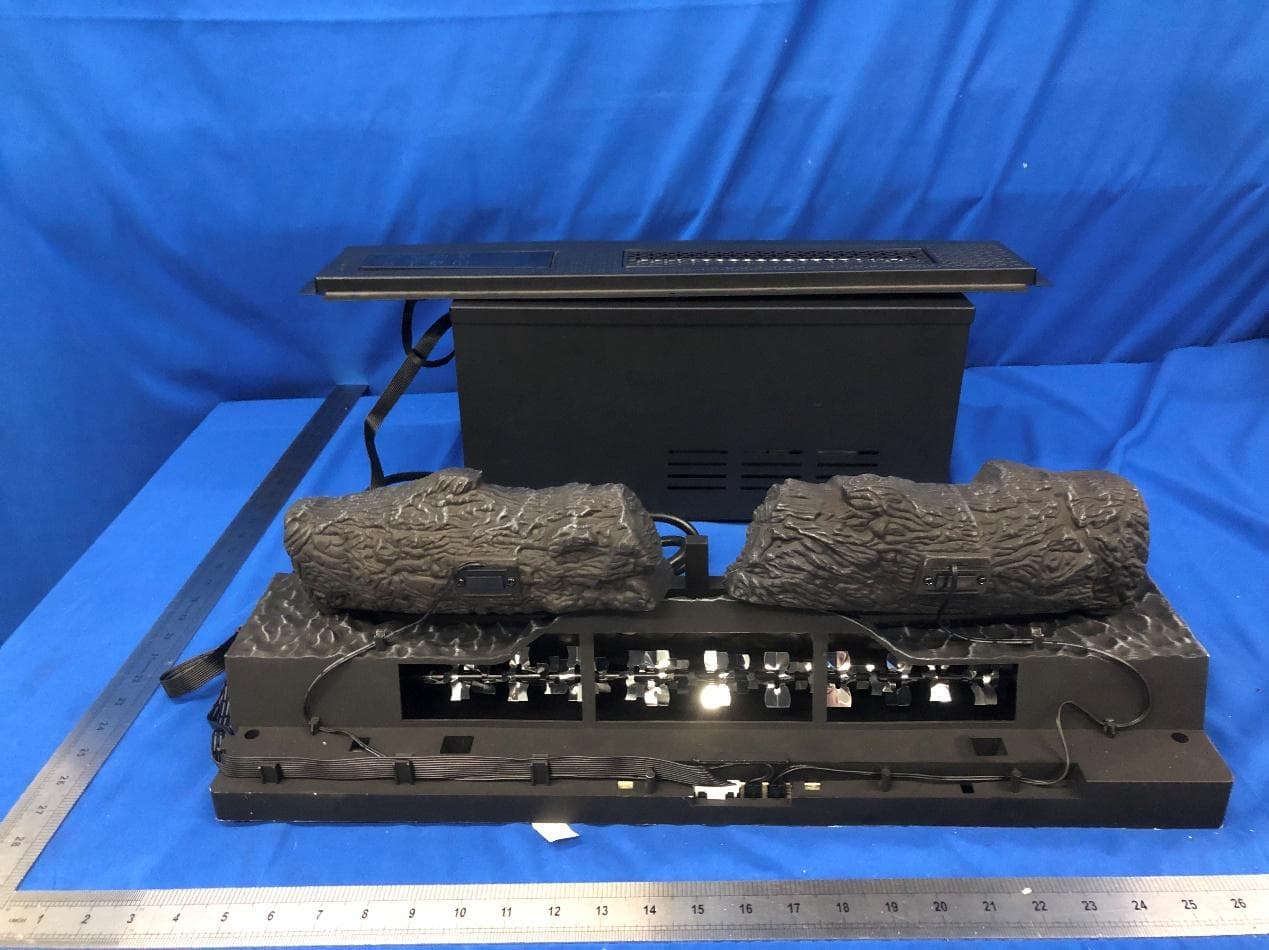
QCD-DI059
May 14, 2026Electric Fireplace
Equipment Class
DTS - Digital Transmission System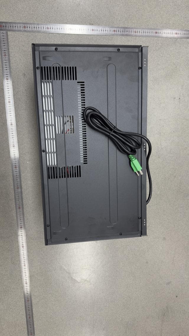
QCD-24II552
May 12, 2026Electric Fireplace
Equipment Class
DTS - Digital Transmission SystemQCD-TS-S-PL01
Apr 14, 2024Speaker
Equipment Class
DSS - Part 15 Spread Spectrum TransmitterQCD-TS-1806
Jul 28, 2015SOUND SYSTEM
Equipment Class
DTS - Digital Transmission System
QCD-CFI-100-1
Jun 17, 2015Heater
Equipment Class
DTS - Digital Transmission System