QDCHAR100Travelers Information Station
American Signal Company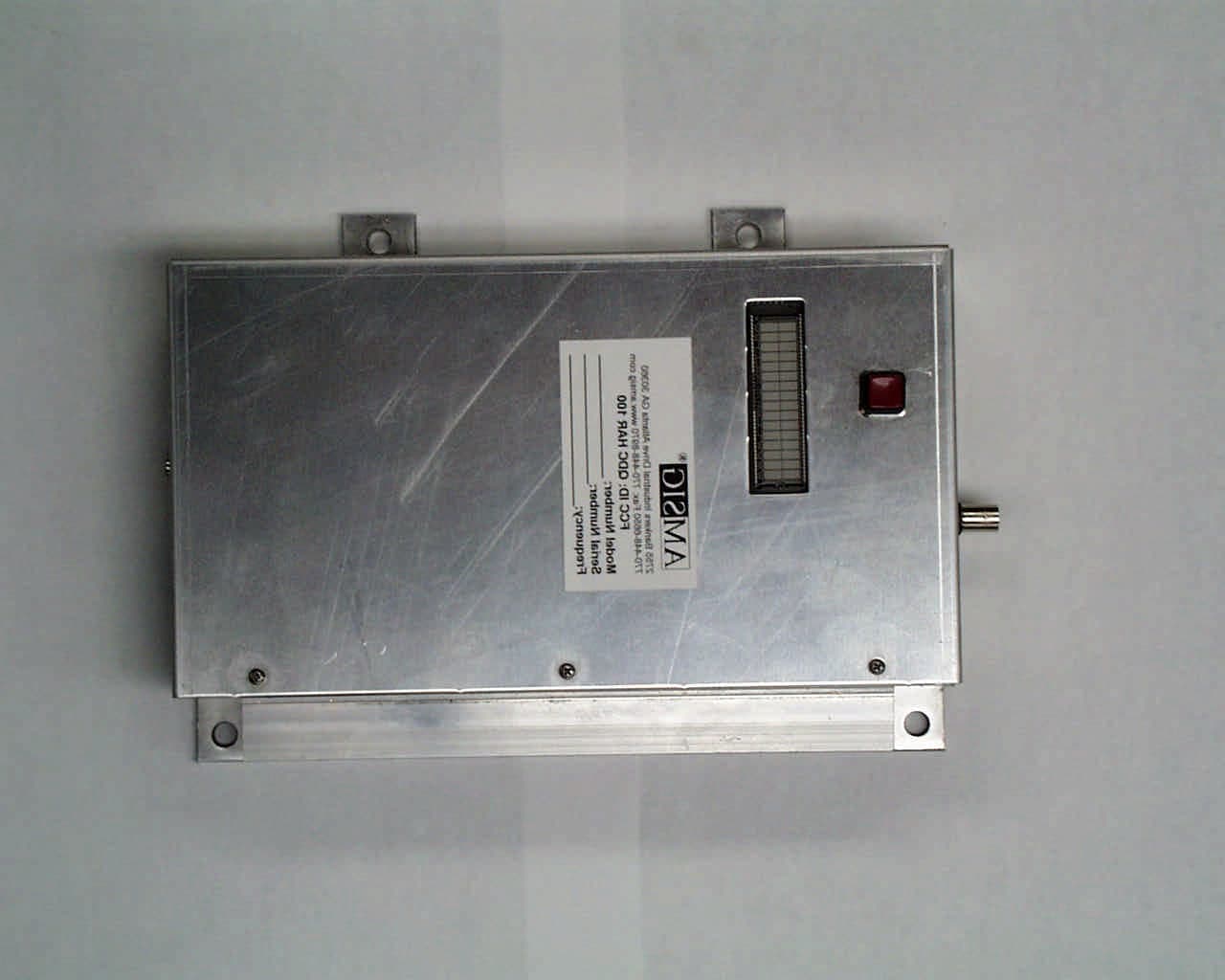
Click to zoom
Application Details
- Equipment Class
- TNB - Licensed Non-Broadcast Station Transmitter
- Date of Grant
- Aug 03, 2003
- Application Purpose
- Original Equipment
- Date of Application
- Aug 03, 2003
- Equipment Note
- Travelers Information Station
- Frequency Range
- 0.53000000 - 1.70000000
- Company
- American Signal Company
- Country
- United States
Documents & Files
Document Text
Text extracted from the exhibit documents filed with the FCC. Open a document above to read the original.
Users Manual
FCC ID: QDCHAR100 FCC ID: QDCHAR100 FCC ID: QDCHAR100 FCC ID: QDCHAR100 FCC ID: QDCHAR100 FCC ID: QDCHAR100 FCC ID: QDCHAR100 FCC ID: QDCHAR100 FCC ID: QDCHAR100
Cover Letter(s)
FCC ID: QDCHAR100 CONFIDENTIALITY REQUEST Federal Communications Commission Date: 5/17/03 Equipment Authorization Branch 7435 Oakland Mills Road Columbia, MD 21046 Gentlemen: American Signal Company respectfully requests confidentiality of certain materials provided with the submission of their device under FCC ID: QDCHAR100 in accordance with FCC Regulations 0.459. The confidentiality request applies to schematics and block diagram contained in Exhibits 4. This device has been developed at considerable effort and expense by American Signal Company. These items are considered as Trade Secrets and therefore public access to the proprietary material could possible result in duplication of equipment that could severely damage the company's business advantage. I appreciate your assistance in this matter. Sincerely, Name: David Blethen Signature: Title: Compliance Technican Date: 5/17/03
Cover Letter(s)
FCC ID: QDCHAR100
Cover Letter(s)
American Telecommunications Certification Body Inc. 6731 Whittier Ave, McLean, VA 22101 July 18, 2003 RE: FCC ID: QDCHAR100_ATCB000525 Attention: Timothy R. Johnson I have a few comments on this Application. 1. Please note that the 731 does not contain the emissions designator information. Please proved the emissions designator for this device. 2. Please note that the tune up procedure states the device is to be set to “just below 10 watts”. The device tested was only 8.7 watts. This is a 14% error between the stated tune up and the actual power measured. Please adjust the power of the device in accordance with the tune up procedure and perform out put power tests. Alternately, please correct the tune up procedure to be closer to the actual power to which the device will be certified (i.e. 8.7 watts). (For example, this may be done by simply stating that the power must be 40dBm +0 / -1dB. This allows the current tune up to be used without reducing the actual power target. Of 10watts) 3. Please note that on page 17 of the report a note states, “This is the LO feed through of the spectrum analyzer and may be ignored.” Please note that the this signal appears to have a peak that might saturate the analyzer. Since the signal is so close to the 530 kHz fundamental being measured, please explain what measures were taken to insure that over loading of the analyzer was not a problem in this measurement. 4. Please note that the Audio Low Pass Filter Response characteristics are tests that are to be done on the device being certified. The charts provided are not clear and appear to be design guideline ‘canned text’ charts; not actual measurements of the device. Please provide actual measurement plots (i.e. not design guidelines) that are representative of the actual device being certified. 5. Please note that the OBW plots provided are questionable. Please note that it is not clear form the hand drawn mask on pages 21 and 22 of the report if the device is compliant. The thick overlay of the hand drawn mask hides parts of the lower side band. While the device may be compliant, it is not easily discernable from the data provided. (FYI this may be because the actual modulating tone appears to be almost 2600hz not 2500Hz) Please provide a more clear indication of how the mask overlays on the SA display. 6. Please note that the frequency tolerance for this type device is not expressed in % or in parts per million but is a absolute 100Hz. Please note that the data on page 28 of your report is incorrectly presented/. Also please note that the device may be failing frequency tolerance requirements as specified in Part 90.242. Please also note that the ambient transmit frequency needs to be the reference frequency. Please correct the report to reflect the proper tolerance limits of 100Hz and please show compliance to the maximum deviation in frequency as less than +/-100Hz. 7. Please note that temperature drift measurements are to be over the entire range using a single reference frequency so that the total drift can be measured. Please explain why the transmit frequency below 20 degrees is different than the actual transmit frequency above 30 degrees? This indicates that you may have a significant drift in that range. 8. Please note that the emissions mask plots should be referenced to the unmodulated carrier. The plots provided only show reference to modulated carriers. Please provide plots showing proper emissions masks in reference to an unmodulated carrier. Dennis Ward mailto:[email protected] The items indicated above must be submitted before processing can continue on the above referenced application. Failure to provide the requested information may result in application termination. z Page 2 July 18, 2003 Correspondence should be considered part of the permanent submission and may be viewed from the Internet after a Grant of Equipment Authorization is issued. Please do not respond to this correspondence using the email reply button. In order for your response to be processed expeditiously, you must submit your documents through the AmericanTCB.com website. Also, please note that partial responses increase processing time and should not be submitted. Any questions about the content of this correspondence should be directed to the sender.
Cover Letter(s)
Response for Request for information (request sent 7/18/03) for Re: FCC ID: QDCHAR100 Applicant:American Signal Company Correspondence Reference Number: N/A 731 Confirmation Number: N/A 1. Please note that the 731 does not contain the emissions designator information. Please proved the emissions designator for this device. The 731 form has been updated. 2. Please note that the tune up procedure states the device is to be set to “just below 10 watts”. The device tested was only 8.7 watts. This is a 14% error between the stated tune up and the actual power measured. Please adjust the power of the device in accordance with the tune up procedure and perform out put power tests. Alternately, please correct the tune up procedure to be closer to the actual power to which the device will be certified (i.e. 8.7 watts). (For example, this may be done by simply stating that the power must be 40dBm +0 / -1dB. This allows the current tune up to be used without reducing the actual power target. Of 10watts) A new report has been provided. Please review. 3. Please note that on page 17 of the report a note states, “This is the LO feed through of the spectrum analyzer and may be ignored.” Please note that the this signal appears to have a peak that might saturate the analyzer. Since the signal is so close to the 530 kHz fundamental being measured, please explain what measures were taken to insure that over loading of the analyzer was not a problem in this measurement. A new report has been provided. Please review. 4. Please note that the Audio Low Pass Filter Response characteristics are tests that are to be done on the device being certified. The charts provided are not clear and appear to be design guideline ‘canned text’ charts; not actual measurements of the device. Please provide actual measurement plots (i.e. not design guidelines) that are representative of the actual device being certified. A new report has been provided. Please review. 5. Please note that the OBW plots provided are questionable. Please note that it is not clear form the hand drawn mask on pages 21 and 22 of the report if the device is compliant. The thick overlay of the hand drawn mask hides parts of the lower side band. While the device may be compliant, it is not easily discernable from the data provided. (FYI this may be because the actual modulating tone appears to be almost 2600hz not 2500Hz) Please provide a more clear indication of how the mask overlays on the SA display. A new report has been provided. Please review. 6. Please note that the frequency tolerance for this type device is not expressed in % or in parts per million but is a absolute 100Hz. Please note that the data on page 28 of your report is incorrectly presented/. Also please note that the device may be failing frequency tolerance requirements as specified in Part 90.242. Please also note that the ambient transmit frequency needs to be the reference frequency. Please correct the report to reflect the proper tolerance limits of 100Hz and please show compliance to the maximum deviation in frequency as less than +/-100Hz. A new report has been provided. Please review. 7. Please note that temperature drift measurements are to be over the entire range using a single reference frequency so that the total drift can be measured. Please explain why the transmit frequency below 20 degrees is different than the actual transmit frequency above 30 degrees? This indicates that you may have a significant drift in that range. A new report has been provided. Please review. 8. Please note that the emissions mask plots should be referenced to the unmodulated carrier. The plots provided only show reference to modulated carriers. Please provide plots showing proper emissions masks in reference to an unmodulated carrier. A new report has been provided. Please review.
External Photos
FCC ID: QDCHAR100 Photo 1. EUT, Top View FCC ID: QDCHAR100 Photo 2. External View Showing Antenna Connection FCC ID: QDCHAR100 Photo 3. External View Showing Power and Audio Inputs
ID Label/Location Info
FCC ID: QDCHAR100
Internal Photos
FCC ID: QDCHAR100 Photo 4. Top View of Board FCC ID: QDCHAR100 Photo 5. Bottom View of Board
Operational Description
FCC ID: QDCHAR100 GENERAL INFORMATION 1.1Product Description The Equipment Under Test (EUT) is a 10 Watt AM Radio Transmitter for use under 90.242 as a Travelers Information Station. The device is a crystal controlled, solid-state, high efficiency AM transmitter. It is continuously variable from 0.1 watt to 10 watts. The device may be operated from 530 kHz to 1.7 MHz per 90.242. The unit is manufactured by the following company: Venture Engineering 2755 D Bankers Industrial Drive Atlanta, GA 30360
Operational Description
FCC ID: QDCHAR100 The device is designed for 24 VDC at 1.5 Amps. The input voltage is reduced by a switching power supply to a DC voltage of around 10 V adjustable at the factory by potentiometer R8 to set the output power at 10 Watts. Input audio is limited by U8, an AGC circuit and lowpass filtered by U9, an LMF40. Modulation level is factory set by potentiometer R5. Amplified audio is supplied to a Class D RF amplifier that is driven by a frequency stable crystal oscillator. An LC filter removes harmonics. A data sheet for the LMF40 low pass filter has been supplied as a separate attachment.
Parts List/Tune Up Info
FCC ID: QDCHAR100 FCC ID: QDCHAR100
Test Report
July 31, 2003 Mr. Stephen P. Hart American Signal Company 2755 Bankers Industrial Drive Atlanta, GA 30360 Dear Mr. Hart: Enclosed please find American Signal Company’s file copy of the FCC Part 90 Certification Report for the 10 Watt Travelers Information Station AM Radio Transmitter. Please sign the signature page of the report and keep it in your files as proof that the product has been tested. If you have any questions, please don't hesitate to call. Thank you for your business. Sincerely, Timothy R. Johnson NARTE Certified EMC Engineer No. EMC-002205-NE American Signal Company FCC Part 90, Certification Application 10 Watt Travelers Information Station AM Radio Transmitter July 31, 2003 MEASUREMENT/TECHNICAL REPORT COMPANY NAME:American Signal Company MODEL:10 Watt Travelers Information Station AM Radio Transmitter FCC ID:QDCHAR100 DATE:July 31, 2003 This report concerns (check one): Original grant X Class II change_____ Equipment type: Travelers Information Station Deferred grant requested per 47 CFR 0.457(d)(1)(ii)? yes_____ No X If yes, defer until:_________________ date N.A. agrees to notify the Commission by N.A. date of the intended date of announcement of the product so that the grant can be issued on that date. Report prepared by: United States Technologies, Inc. 3505 Francis Circle Alpharetta, GA 30004 Phone Number: (770) 740-0717 Fax Number: (770) 740-1508 Report Reviewed By: Name: Timothy R. Johnson NARTE Certified Engineer EMC-002205-NE FCC ID: QDCHAR100 TABLE OF CONTENTS AGENCY AGREEMENT LETTER OF CONFIDENTIALITY SECTION 1 GENERAL INFORMATION 1.1 Product Description 1.2 Related Submittal(s) SECTION 2 TESTS AND MEASUREMENTS 2.1 Configuration of Tested EUT 2.2 Test Facility 2.3 Test Equipment 2.4 Modifications 2.5 Antenna Description 2.6 RF Power Output 2.7 Modulation Characteristics 2.8 Occupied Bandwidth 2.9 Spurious Emissions at Antenna Terminals 2.10 Field Strength of Spurious Radiation 2.11 Frequency Stability 2.12 Emissions Type 2.13 Transient Frequency Behavior SECTION 3 LABELING INFORMATION SECTION 4 BLOCK DIAGRAM(S)/ SCHEMATIC(S) SECTION 5 PHOTOGRAPHS SECTION 6 RF TECHNICAL INFORMATION SECTION 7 TUNE UP PROCEDURE SECTION 8 USER'S MANUAL FCC ID: QDCHAR100 SECTION 1 GENERAL INFORMATION FCC ID: QDCHAR100 GENERAL INFORMATION 1.1Product Description The Equipment Under Test (EUT) is a 10 Watt AM Radio Transmitter for use under 90.242 as a Travelers Information Station. The device is a crystal controlled, solid-state, high efficiency AM transmitter. It is continuously variable from 0.1 watt to 10 watts. The device may be operated from 530 kHz to 1.7 MHz per 90.242. The unit is manufactured by the following company: Venture Engineering 2755 D Bankers Industrial Drive Atlanta, GA 30360 FCC ID: QDCHAR100 1.2Related Submittal(s)/Grant(s) The EUT will be used to send audio transmissions. The transmitter presented in this report operates with typical AM radio receivers. The EUT is subject to the following authorization: a) Certification as a transmitter as specified by Part 90.242. The information contained in this report is presented for the certification authorization for the EUT. FCC ID: QDCHAR100 SECTION 2 TESTS AND MEASUREMENTS FCC ID: QDCHAR100 TEST AND MEASUREMENTS 2.1 Configuration of Tested System Prepared in accordance with the requirements of the FCC Rules and Regulations Part 90.242. All measurements are peak unless stated otherwise. The video filter associated with the spectrum analyzer was off throughout the evaluation process. Interconnecting cables were manipulated as necessary to maximize emissions. A block diagram of the tested system is shown in Figure 1. Test configuration photographs for spurious and fundamental emissions are shown in Figure 2. The sample used for testing was received by U.S. Technologies on November 21, 2002 in good condition. New samples were received July 25 for additional testing. 2.2 Test Facility Testing was performed at US Tech's measurement facility at 3505 Francis Circle, Alpharetta, GA. 2.3 Test Equipment Table 2 describes test equipment used to evaluate this product. 2.4 Modifications No modifications were made by US Tech, to bring the EUT into compliance with FCC Part 90 limits for the transmitter portion of the EUT. FCC ID: QDCHAR100 FIGURE 1 TEST CONFIGURATION 60 dB attenuator Transmitter (EUT) 1m u from 24 VDC Power Source 6' u From Audio Generator Source To Measurement Equipment FCC ID: QDCHAR100 Test Date:November 21, 2002 UST Project:02-0414 Customer:American Signal Company Model:HAR100 FIGURE 2a Photograph(s) for Spurious Emissions Since this test is required only for transmitters operating > 25 MHz, this test was not performed. FCC ID: QDCHAR100 TABLE 1 EUT and Peripherals PERIPHERAL MANUFACTURER MODEL NUMBER SERIAL NUMBER FCC ID:CABLES P/D Transmitter (EUT) American Signal Company 10 Watt Travelers Information Station UnknownQDCHAR100 (Pending) 1m u 6' u 60 dB Attenuator Provided by American Signal Company NoneNoneNone FCC ID: QDCHAR100 TABLE 2 TEST INSTRUMENTS TYPEMANUFACTURERMODELSN. SPECTRUM ANALYZERHEWLETT-PACKARD8593E3205A00124 TEMPERATURE CHAMBER THERMOTRONSM1617095 Note: An external attenuator was provided by American Signal Company. Insertion Loss measurements over the frequency range measured were made by U.S. Technologies. FCC ID: QDCHAR100 2.5 Antenna Description (FCC Section 90.242) 90.242(b)(3) For a station employing a cable antenna, the following restrictions apply: (i)The length of the cable antenna shall not exceed 3.0 km (1.9 miles). (ii) Transmitter RF output power shall not exceed 50 watts and shall be adjustable downward to enable the user to comply with the specified field strength limit. (iii) The field strength of the emission on the operating frequency shall not exceed 2 mV/m when measured with a standard field strength meter at a distance of 60 meters (197 feet) from any part of the station. 90.242(b)(4) For a station employing a conventional radiating antenna(s) (ex. vertical monopole, direct…
Text truncated - open the document above for the full version.
Contact Information
Applicant
Stephen P Hart(President)
Technical Contact
U.S. TechnologiesTimothy R Johnson
3505 Francis Circle · Alpharetta, Georgia · United States
Technical Specifications
| # | Rule Parts | Frequency Range | Power Output | Emission | Tolerance |
|---|---|---|---|---|---|
| 1 | 90 | 0.53 MHz - 1.7 MHz | 10 W | 6K00A3E | 24.0000000000 Hz |