QDMPSP22UW100 MK II
DREAMUS COMPANY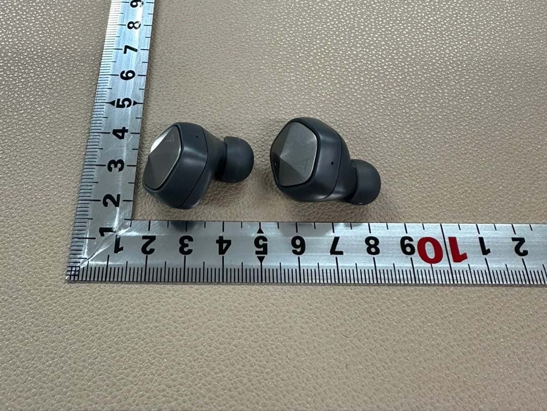
Click to zoom
Application Details
- Equipment Class
- DSS - Part 15 Spread Spectrum Transmitter
- Date of Grant
- May 04, 2023
- Application Purpose
- Original Equipment
- Date of Application
- May 04, 2023
- Equipment Note
- UW100 MK II
- Frequency Range
- 2402.00000000 - 2480.00000000
- Company
- DREAMUS COMPANY
- Country
- South Korea
Documents & Files
Document Text
Text extracted from the exhibit documents filed with the FCC. Open a document above to read the original.
Users Manual
INSTRUCTION BOOK PSP22 User Guide CONTENTS Before Using the Product Included Items Parts Names Charging Power Management Connections Connecting to a device Getting Started _01 Using the Earbuds Listening to Music Making a Phone Call Voice Recognition Using the App Using the Device _02 Safety Precautions Troubleshooting Copyright Certifications Disclaimers Specifications Miscellaneous _03 02 03 04 05 08 09 10 13 14 15 16 17 20 22 25 25 26 27 User Guide Getting Started 02 The descriptions contained in this instruction book are based on the product's default settings. The contents of this instruction book may differ from the actual product due to changes in the manufacturer’s specifications. The images shown in this instruction book may differ from the actual product. Some features may not be available depending on the manufacturer of the mobile device and the specifications of the model. Please check with the manufacturer of the mobile device. Do not allow water to enter the product. It may result in product failure. Do not wear the product when swimming or taking a shower. Failures due to damage from liquids are not covered by warranty. Any modification of the software provided by the manufac- turer, or any installation of software obtained through an unapproved route can cause the product to malfunction or fail, and will void the warranty. Before Using the Product Getting Started 03 User Guide Ear tips: Select the ear tips that best fit your ears and affix them onto the earbuds. Charging case: Stores and charges the earbuds. Charging cable: Connects the charging case to a charger to charge the product. Quick Start Guide: A basic guide for using the product. Warranty Card: Please keep the warranty card since it is required when requesting after-sales service. Product User Guide: The User Guide can be downloaded from the Astell&Kern website: [http://www.astellnkern.com Support > Download]. Components may change without prior notice to improve the performance or quality of the product. Quick Start Guide & Warranty Card Charging cableCharging case Ear tips (5 sizes)TWS earbuds The DC 5V/2A charger is sold separately. Please use a charger that meets the specifications. Included Items User Guide Getting Started 04 The appearance of the product as well as the information printed and engraved on the product may vary depending on the manufacturer's specifications. LED indicatorTouch button MicrophoneCharging pin Charging pinCharging port (USB Type-C) Ear tipsProximity sensor Ear tips: Select the ear tips that best fit your ears and affix them onto the earbuds. Proximity sensor: Detects when you're wearing the earbuds. Charging pin: The charging pins in the earbuds contact the charging pins located inside the charging case to charge the earbuds. Touch button: Controls various features such as music playback. Microphone: Using for calls. Charging case Charging pin: The earbuds are mounted onto the charging pins for charging. LED charging indicator: Indicates the charging states of the earbuds and charging case. Charging port (USB Type-C): Used to charge the product with the connector cable. Parts Names Getting Started 05 User Guide Wireless charging The charging case has built-in wireless charging coils that allow the battery to be charged using a wireless charger or other devices that act as a wireless charger. 1. Check the direction of the earbuds and place them to fit the grooves inside the charging case. 2. Place the charging case on top of the wireless charger so that the center of its bottom surface is touching the center of the wireless charger. 3. The blue or green LEDs blink repeatedly depending on the charging state, and the LEDs turn off when charging is complete. When charging is complete, disconnect the charging case from the charger. Wired charging 1. Notice the direction of the earbuds when replacing them in the charging case so they come in contact with the charging pins. 2. Connect the [charging port] on the back of the charging case with the charger using the USB Type C cable included in the package. 3. Plug the charger into an outlet. 4. The blue or green LEDs blink repeatedly depending on the charging state, and the LEDs turn off when charging is complete. When charging is complete, disconnect the charging case from the charger. Charging User Guide Getting Started 06 Be sure to use the USB Type C cable provided with the product. Cables that do not meet the specifications may cause product failure. Recommended charger specifications: DC 5V/2A Using a charger that does not meet the product’s specifications may cause the product to fail. Any damage caused by using an unauthorized charger outside the recommended specifications will not be covered by warranty service. If the product is being used for the first time after purchase, or if the product has been left unused for a long time, or if the battery is dead, charge for at least 10 minutes before using. If the battery is completely discharged as a result of not using the product for a long time, battery performance may be compromised. Please frequently check the battery’s charging state and charge the battery when its level is low. Sweat or moisture on the charging pin can cause corrosion on the product. Make sure to completely remove any moisture before placing the earbuds into the charging case. The product and charger may become hot during charging. This is normal and does not affect the life or functioning of the product. If the battery temperature rises above a certain level, charging may stop for safety reasons. If charging wirelessly, remove the charging case from the wireless charging pad and allow it to cool before recharging. Make sure to remove any conductive material (metals, magnets, etc.) from the back of the charging case before placing it on top of the wireless charger. Failing to do so may damage the charging case. Connecting the charging case to a computer, etc., may result in a longer charging time. Be careful n…
Text truncated - open the document above for the full version.
Attestation Statements
Attestation Statements Date: April 14, 2023 TO: Federal Communications Commission Authorization and Evaluation Division 7435 Oakland Mills Road Columbia, MD 21046, USA RE: Attestation Statements Part 2.911(d)(7) request for QDMPSP22 DREAMUS COMPANY, the undersigned, hereby authorize Invixion Inc. to act as our designated U.S. agent for service of process, DREAMUS COMPANY accepts to maintain an agent for no less than one year after the grantee has terminated all marketing and importation or the conclusion of any Commission-related proceeding involving the equipment. Invixion Inc. accepts the responsibility to act as designated U.S. agent for service of process, provides an agent for no less than one year after the grantee has terminated all marketing and importation or the conclusion of any Commission-related proceeding involving the equipment. Applicant Information: Company name: DREAMUS COMPANY Contact Name: JeongHoon, Yu Address: 311, Gangnam-daero, Seocho-gu, Seoul, Republic of Korea Telephone No: 82-2-6240-9118 Email: [email protected] U.S. Agent Information: Company Name: Invixion Inc. Address: 19600 Fairchild, #125, Irvine CA 92612 FRN Number: 0033404864 Contact Name: Owen Kwon Telephone No: (949) 336-4535 Email: [email protected] Applicant Signature: Agent Signature: (if the agent is different from the applicant) Applicant printed name: JeongHoon, Yu Agent printed name: Owen Kwon
Attestation Statements
DREAMUS COMPANY Date: April 13, 2023 Eurofins Electrical and Electronic Testing NA, Inc. 914 West Patapsco Avenue Baltimore, MD 21230 RE: Attestation Statements Part 2.911(d)(5)(i) request for QDMPSP22 [DREAMUS COMPANY] (“the applicant”) certifies that the equipment for which authorization is sought is not “covered” equipment prohibited from receiving an equipment authorization pursuant to section 2.903 of the FCC rules. Sincerely, (Applicant signature) (Applicant printed name) JeongHoon, Yu DREAMUS COMPANY Date: April 13, 2023 Eurofins Electrical and Electronic Testing NA, Inc. 914 West Patapsco Avenue Baltimore, MD 21230 RE: Attestation Statements Part 2.911(d)(5)(ii) request for QDMPSP22 [DREAMUS COMPANY] (“the applicant”) certifies that, as of the date of the filing of the application, the applicant is not identified on the Covered List as an entity producing “covered” equipment. Sincerely, (Applicant signature) (Applicant printed name) JeongHoon, Yu
Cover Letter(s)
DREAMUS COMPANY 311, Gangnam-daero, Seocho-gu, Seoul, Republic of Korea Date: April 13, 2023 Eurofins Electrical and Electronic Testing NA, Inc. 914 West Patapsco Avenue Baltimore, MD 21230 RE: CONFIDENTIALITY REQUEST FOR (UW100 MK II / PSP22 # QDMPSP22 #) To Whom It May Concern: This letter serves as an official request for confidentiality under sections 0.457 and 0.459 of CFR 47. We have requested that the (below list) required to be submitted with this application be permanently withheld from public review. Permanent Confidential Request -. Schematics -. Operational Description -. Block Diagram SPECIFY REASON FOR REQUEST (i.e. the above documents are company proprietary information that could never get into the possession of your competition). Please contact me if there is any information you may need. Sincerely, JeongHoon, Yu / Manager
Cover Letter(s)
DREAMUS COMPANY 311, Gangnam-daero, Seocho-gu, Seoul, Republic of Korea Date: April 13, 2023 Eurofins Electrical and Electronic Testing NA, Inc. 914 West Patapsco Avenue Baltimore, MD 21230 RE: CONFIDENTIALITY REQUEST FOR (UW100 MK II / PSP22 # QDMPSP22 #) To Whom It May Concern: This letter serves as an official request for confidentiality under sections 0.457 and 0.459 of CFR 47. We have requested that the (below list) required to be submitted with this application be short-term Confidentiality for a period of 180 days after grant is issued. Short-Term Confidential Request -. External Photos -. Internal Photos -. Test set-up photo -. User Manual SPECIFY REASON FOR REQUEST (i.e. These documents contain detailed system and equipment descriptions and related information about the product, which we considers to be proprietary, confidential, and a custom design and otherwise, would not release to the general public. Since this design is a basis from which future technological products will evolve, we feel that this information would be of benefit to our competitors, and that the disclosure of the information in these documents would give our competitors an unfair advantage in the market. Please contact me if there is any information you may need. Sincerely, JeongHoon, Yu / Manager
Cover Letter(s)
DREAMUS COMPANY 311, Gangnam-daero, Seocho-gu, Seoul, Republic of Korea Date: April 13, 2023 Eurofins Electrical and Electronic Testing NA, Inc. 914 West Patapsco Avenue Baltimore, MD 21230 RE: LETTER OF AGENT AUTHORIZATION To Whom It May Concern: We, the undersigned, hereby authorize Ms. Chloe Lee/Deputy General Manager of Eurofins KCTL Co.,Ltd. to act on our behalf in all matters relating to application for equipment authorization, including the signing of all documents relating to these matters. We also hereby certify that no party to the application authorized hereunder is subject to the denial of benefits, including FCC benefits, pursuant to Section 5301 of the Anti-Drug Abuse Act of 1988, 21 U.S.C.853(a). This agreement expires one year from the current date. Sincerely, JeongHoon, Yu / Manager
External Photos
This document shall not be reproduced, except in full, without the written approval External photos of EUT This document shall not be reproduced, except in full, without the written approval This document shall not be reproduced, except in full, without the written approval This document shall not be reproduced, except in full, without the written approval This document shall not be reproduced, except in full, without the written approval
ID Label/Location Info
The product is too small, so we put the FCC ID on the user manual and device packaging. Please refer to page 2 for FCC ID on user manual location. Please refer to page 3 for FCC ID on device packaging location. Miscellaneous 25 User Guide Certifica- tions Copyright Dreamus Company retains the rights to patents, trademarks, copyrights, and other intellectual property rights related to this manual. No contents of this user manual may be duplicated or reproduced in any format or by any means without the prior approval of Dreamus Company. Using or reproducing, in whole or part, the contents of this document is subject to penalties. Software, audio, video, and any other copyrighted contents are protected in accordance with relevant copyright laws. The user accepts all legal responsibility for the unauthorized reproduction or distribution of the copyrighted contents from this product. Companies, organizations, products, people, and events used in the examples are fictional. Dreamus Company has no intention to be associated with any company, institution, product, person, or incident through this instruction book, and no such inference should be made. It is the responsibility of the user to comply with applicable copyright laws. Copyright © Dreamus Company. All Rights Reserved. KC / FCC / CE / TELEC Class B Device (Communication equipment for residential use): This is a Class B Device and is registered for EMC requirements for residential use. This device can be used in residential areas and all other areas. Check information about KC/FCC/CE TELEC certification at [settings - system information - regulations] FCC ID will be in the manual and the product package because the device dimension is too small to accommodate the FCC ID in 8 point font. FCC ID: QDMPSP22 This device complies with Part 15 of the FCC Rules, Operation is subject to the following two conditions: (1) this device may not cause harmful interference, and (2) this device must accept any interference received, including interference that may cause undesired operation.
Internal Photos
This document shall not be reproduced, except in full, without the written approval Internal photos of EUT This document shall not be reproduced, except in full, without the written approval Coil Antenna This document shall not be reproduced, except in full, without the written approval This document shall not be reproduced, except in full, without the written approval This document shall not be reproduced, except in full, without the written approval This document shall not be reproduced, except in full, without the written approval This document shall not be reproduced, except in full, without the written approval This document shall not be reproduced, except in full, without the written approval This document shall not be reproduced, except in full, without the written approval This document shall not be reproduced, except in full, without the written approval Earbuds_Left This document shall not be reproduced, except in full, without the written approval This document shall not be reproduced, except in full, without the written approval Earbuds_Right This document shall not be reproduced, except in full, without the written approval
RF Exposure Info
This test report shall not be reproduced, except in full, without the written approval * RF Exposure FCC ID: QDMPSP22 1. Regulation According to the KDB 447498 D01 V06, the following RF exposure evaluation shall to demonstrate RF exposure compliance. Unless specifically required by the published RF exposure KDB procedures, standalone 1-g head or body and 10-g extremity SAR evaluation for general population exposure conditions, by measurement or numerical simulation, is not required when the corresponding SAR Test Exclusion Threshold condition(s), listed below, is (are) satisfied. These test exclusion conditions are based on source-based time-averaged maximum conducted output power of the RF channel requiring evaluation, adjusted for tune-up tolerance, and the minimum test separation distance required for the exposure conditions. The minimum test separation distance defined in 4.1 f) is determined by the smallest distance from the antenna and radiating structures or outer surface of the device, according to the host form factor, exposure conditions and platform requirements, to any part of the body or extremity of a user or bystander. To qualify for SAR test exclusion, the test separation distances applied must be fully explained and justified, typically in the SAR measurement or SAR analysis report, by the operating configurations and exposure conditions of the transmitter and applicable host platform requirements, according to the required published RF exposure KDB procedures. When no other RF exposure testing or reporting are required, a statement of justification and compliance must be included in the equipment approval, in lieu of the SAR report, to qualify for SAR test exclusion. When required, the device specific conditions described in the other published RF exposure KDB procedures must be satisfied before applying these SAR test exclusion provisions; for example, handheld PTT two-way radios, handsets, laptops and tablets, etc. a) For 100 ㎒ to 6 ㎓ and test separation distances ≤ 50 ㎜, the 1-g and 10-g SAR test exclusion thresholds are determined by the following: [(max. power of channel, including tune-up tolerance, ㎽) / (min. test separation distance, ㎜)] ꞏ [√f(㎓)] ≤ 3.0 for 1-g SAR, and ≤ 7.5 for 10-g extremity SAR,30 where ● f(㎓) is the RF channel transmit frequency in ㎓ ● Power and distance are rounded to the nearest ㎽ and mm before calculation ● The result is rounded to one decimal place for comparison ● The values 3.0 and 7.5 are referred to as numeric thresholds in step b) below The test exclusions are applicable only when the minimum test separation distance is ≤ 50 ㎜, and for transmission frequencies between 100 ㎒ and 6 ㎓. When the minimum test separation distance is < 5 ㎜, a distance of 5 ㎜ according to 4.1 f) is applied to determine SAR test exclusion. b) For 100 ㎒ to 6 ㎓ and test separation distances > 50 ㎜, the 1-g and 10-g SAR test exclusion thresholds are determined by the following (also illustrated in Appendix B): 1) {[Power allowed at numeric threshold for 50 ㎜ in step a)] + [(test separation distance – 50 ㎜)ꞏ(f(㎒)/150)]} ㎽, for 100 ㎒ to 1500 ㎒ 2) {[Power allowed at numeric threshold for 50 ㎜ in step a)] + [(test separation distance – 50 ㎜)ꞏ10]} ㎽, for > 1500 ㎒ and ≤ 6 ㎓ c) For frequencies below 100 ㎒, the following may be considered for SAR test exclusion (also illustrated This test report shall not be reproduced, except in full, without the written approval in Appendix C): 1) For test separation distances > 50 ㎜ and < 200 ㎜, the power threshold at the corresponding test separation distance at 100 ㎒ in step b) is multiplied by [1 + log(100/f(㎒))] 2) For test separation distances ≤ 50 ㎜, the power threshold determined by the equation in c) 1) for 50 ㎜ and 100 ㎒ is multiplied by ½ 3) SAR measurement procedures are not established below 100 ㎒. When SAR test exclusion cannot be applied, a KDB inquiry is required to determine SAR evaluation requirements for any SAR test results below 100 ㎒ to be acceptable. 2. Result 2-1. Calculation Result of RF Exposure Mode Mode Test Frequency [㎓] Max Tune Up Power [㏈m] Conducted Output Power [㎽] Min. Test Separation Distance [㎜] SAR Test Exclusion Thresholds ≤ 7.5 for 10-g SAR Left EAR BDR (GFSK) 2.480 6.00 3.98 5.00 1.25 EDR (π/4DQPSK) 2.480 4.00 2.51 5.00 0.79 EDR (8DPSK) 2.480 4.00 2.51 5.00 0.79 LE_1 Mbps, 37 Packet 2.480 5.00 3.16 5.00 1.00 LE_2 Mbps, 37 Packet 2.480 5.00 3.16 5.00 1.00 Right EAR BDR (GFSK) 2.402 6.00 3.98 5.00 1.23 EDR (π/4DQPSK) 2.402 4.00 2.51 5.00 0.78 EDR (8DPSK) 2.402 4.00 2.51 5.00 0.78 LE_1 Mbps, 37 Packet 2.402 5.00 3.16 5.00 0.98 LE_2 Mbps, 37 Packet 2.402 5.00 3.16 5.00 0.98 Note: 1. SAR test exclusion thresholds = [(max. power of channel, including tune-up tolerance, ㎽)/(min. test separation distance, ㎜)] ꞏ [√f(㎓)] This test report shall not be reproduced, except in full, without the written approval 3. Target power and tolerance, Max tuneup power EarBud Mode Test frequency [㎒] Target Power [㏈m] Max Tune Up Power [㏈m] Measured Average Power [㏈m] Left EAR BDR (GFSK) 2402 5.0 6.0 4.92 2441 5.05 2480 5.49 EDR (π/4DQPSK) 2402 3.0 4.0 2.00 2441 2.12 2480 2.50 EDR (8DPSK) 2402 3.0 4.0 2.03 2441 2.12 2480 2.50 LE 1 Mbps, 37 Packet 2402 4.0 5.0 3.28 2440 3.46 2480 3.62 LE 2 Mbps, 37 Packet 2402 4.0 5.0 3.30 2440 3.48 2480 3.64 Right EAR BDR (GFSK) 2402 5.0 6.0 5.85 2441 5.53 2480 5.46 EDR (π/4DQPSK) 2402 3.0 4.0 2.85 2441 2.49 2480 2.51 EDR (8DPSK) 2402 3.0 4.0 2.86 2441 2.50 2480 2.50 LE 1 Mbps, 37 Packet 2402 4.0 5.0 4.21 2440 3.89 2480 3.52 LE 2 Mbps, 37 Packet 2402 4.0 5.0 4.28 2440 3.95 2480 3.59 Note: 1. Tolerance = -1.5/+1 ㏈ 4. RF Exposure Compliance Issue Therefore, EUT is not required the SAR Evaluation.
Test Report
EARBUDS_ANT(LEFT) [HWI-BTL-UW100MK2] 1 / 7 Dreamus Corp. APPROVAL SHEET UW100MK2 NO MODEL FREQUENCY 1 HWI-BTL-UW100MK2 BLUET00TH 2400 ~ 2483.5 MHz SUPPLIER CUSTOMER Engineer Review Approved Engineer Review Approved 23/03/02 23/03/02 HANWOOL TECHNOLOGY CO., LTD #1002 IT303-DONG, PUCHONTECHNOPARK III 36-1 SAMJUNG-DONG, OHJUNG-GU, KYOUNG GI-DO, KOREA TEL: 032) 624-2555 FAX: 032) 624-2559 2 / 7 HISTORY SHEET ITEM FPCB ANTENNA Developed by Kyoung-Min Lee Part Name HWI-BTL-UW100MK2 Director Rev. No. Date Description Etc. 0 2023-03-02 Initial Version 3 / 7 ANTENNA SPECIFICATION 1. MODEL: HWI-BTL-UW100MK2 2. APPLICATION: This specification is provided for BLUETOOTH ANTENNA. 3 ANTENNA used condition ■Portable ■Fixing ■Movement ■Out-door ■In-door ■Etc( ) 4. ANTENNA Drawing #3. Attached : Drawing paper 5. Electrical specification and performance Satisfied next data with real used or similar environment conditions. No. ELECTRICAL DATA SPECIFICATIONS REMARK 5. 1 FREQUENCY RANGE BLUETOOTH 2400 ~ 2483.5 MHz 5. 2 IMPEDANCE 50 Ω NOMINAL 5. 3 V. S. W. R BLUETOOTH Less than 1 : 2.78 #1. Attached 5. 4 PEAK GAIN BLUETOOTH -3.46 dBi #2. Attached 5. 5 RADIATION PATTERN OMNI – DIRECTIONAL 5. 6 POLARIZATION LINEAR 6. Hardware specification and mechanical No. MECHANICAL SPECIFICATIONS REMARK 2. 6. 1 FPCB Size [W X H X T] 13.40 X 13.80 X 0.15 (mm) 4 / 7 7. SINUSOIDAL VIBRATION Vibration Frequencies : 5- 55 Hz (1 cycle) Sweep Rate : 1 cycle/min Maximum Amplitude : A – 1 mm Maximum Acceleration : 2 g Measuring method Antenna is combined in the test equipment. The vibration is done X and Y direction (left, right, up and down) according to below image. It continued for 2 hours each direction. 8. OPERATING TEMPERATURE Temperature : - 40°C / +70°C Demands : Set Antenna and Cable for 72 hours each temperature. No visual and mechanical changes. The fitting and mold will be unchanged mechanically during the test. The antenna shall satisfy the electrical data 9. HUMIDITY Condition : 95% / +70°C Measuring method Antenna is placed in climatic chamber for 72 hours. Antenna is taken out from the chamber and measured after another 24 hours in room temperature Demands : No visual and mechanical changes. The fitting and mold will be unchanged mechanically during the test. The antenna shall satisfy the electrical data. 10. TEST and Q/C This specification is according to fixed demands and suitable Hanwool technology Q/C provision. But it is possible to skip No. 7~9 demands, after consultation with buyer. 5 / 7 - #1. Attached : VSWR + Matching Value 6 / 7 - #2. Attached : RADIATION PATTERN(GAIN)_BLUETOOTH 7 / 7 - #3. Drawing paper EARBUDS_ANT(RIGHT) [HWI-BTR-UW100MK2] 1 / 7 Dreamus Corp. APPROVAL SHEET UW100MK2 NO MODEL FREQUENCY 1 HWI-BTR-UW100MK2 BLUET00TH 2400 ~ 2483.5 MHz SUPPLIER CUSTOMER Engineer Review Approved Engineer Review Approved 23/03/02 23/03/02 HANWOOL TECHNOLOGY CO., LTD #1002 IT303-DONG, PUCHONTECHNOPARK III 36-1 SAMJUNG-DONG, OHJUNG-GU, KYOUNG GI-DO, KOREA TEL: 032) 624-2555 FAX: 032) 624-2559 2 / 7 HISTORY SHEET ITEM FPCB ANTENNA Developed by Kyoung-Min Lee Part Name HWI-BTR-UW100MK2 Director Rev. No. Date Description Etc. 0 2023-03-02 Initial Version 3 / 7 ANTENNA SPECIFICATION 1. MODEL: HWI-BTR-UW100MK2 2. APPLICATION: This specification is provided for BLUETOOTH ANTENNA. 3 ANTENNA used condition ■Portable ■Fixing ■Movement ■Out-door ■In-door ■Etc( ) 4. ANTENNA Drawing #3. Attached : Drawing paper 5. Electrical specification and performance Satisfied next data with real used or similar environment conditions. No. ELECTRICAL DATA SPECIFICATIONS REMARK 5. 1 FREQUENCY RANGE BLUETOOTH 2400 ~ 2483.5 MHz 5. 2 IMPEDANCE 50 Ω NOMINAL 5. 3 V. S. W. R BLUETOOTH Less than 1 : 2.78 #1. Attached 5. 4 PEAK GAIN BLUETOOTH -3.46 dBi #2. Attached 5. 5 RADIATION PATTERN OMNI – DIRECTIONAL 5. 6 POLARIZATION LINEAR 6. Hardware specification and mechanical No. MECHANICAL SPECIFICATIONS REMARK 2. 6. 1 FPCB Size [W X H X T] 13.40 X 13.80 X 0.15 (mm) 4 / 7 7. SINUSOIDAL VIBRATION Vibration Frequencies : 5- 55 Hz (1 cycle) Sweep Rate : 1 cycle/min Maximum Amplitude : A – 1 mm Maximum Acceleration : 2 g Measuring method Antenna is combined in the test equipment. The vibration is done X and Y direction (left, right, up and down) according to below image. It continued for 2 hours each direction. 8. OPERATING TEMPERATURE Temperature : - 40°C / +70°C Demands : Set Antenna and Cable for 72 hours each temperature. No visual and mechanical changes. The fitting and mold will be unchanged mechanically during the test. The antenna shall satisfy the electrical data 9. HUMIDITY Condition : 95% / +70°C Measuring method Antenna is placed in climatic chamber for 72 hours. Antenna is taken out from the chamber and measured after another 24 hours in room temperature Demands : No visual and mechanical changes. The fitting and mold will be unchanged mechanically during the test. The antenna shall satisfy the electrical data. 10. TEST and Q/C This specification is according to fixed demands and suitable Hanwool technology Q/C provision. But it is possible to skip No. 7~9 demands, after consultation with buyer. 5 / 7 - #1. Attached : VSWR + Matching Value 6 / 7 - #2. Attached : RADIATION PATTERN(GAIN)_BLUETOOTH 7 / 7 - #3. Drawing paper
Test Report
verify No.774039805318 Eurofins KCTL Co.,Ltd. 65, Sinwon-ro, Yeongtong-gu, Suwon-si, Gyeonggi-do, 16677, Korea TEL: 82-70-5008-1021 FAX: 82-505-299-8311 www.kctl.co.kr Report No.: KR23-SRF0108 Page (2) of (72) KCTL-TIR001-003/7 (220705) KP23-01715 REPORT REVISION HISTORY Date Revision Page No 2023-04-25 Originally issued - This report shall not be reproduced except in full, without the written approval of Eurofins KCTL Co.,Ltd. This document may be altered or revised by Eurofins KCTL Co.,Ltd. personnel only, and shall be noted in the revision section of the document. Any alteration of this document not carried out by Eurofins KCTL Co.,Ltd. will constitute fraud and shall nullify the document. This test report is a general report that does not use the KOLAS accreditation mark and is not related to KS Q ISO/IEC 17025 and KOLAS accreditation. General remarks for test reports Statement concerning the uncertainty of the measurement systems used for the tests (may be required by the product standard or client) Internal procedure used for type testing through which traceability of the measuring uncertainty has been established: Procedure number, issue date and title: Calculations leading to the reported values are on file with the testing laboratory that conducted the testing. Statement not required by the standard or client used for type testing Eurofins KCTL Co.,Ltd. 65, Sinwon-ro, Yeongtong-gu, Suwon-si, Gyeonggi-do, 16677, Korea TEL: 82-70-5008-1021 FAX: 82-505-299-8311 www.kctl.co.kr Report No.: KR23-SRF0108 Page (3) of (72) KCTL-TIR001-003/7 (220705) KP23-01715 CONTENTS 1. General information ...................................................................................................... 4 2. Device information ........................................................................................................ 4 2.1. Accessory information ............................................................................................ 5 2.2. Frequency/channel operations ................................................................................ 5 2.3. RF power setting in TEST SW ................................................................................ 5 3. Antenna requirement .................................................................................................... 6 4. Summary of tests .......................................................................................................... 7 5. Measurement uncertainty ............................................................................................. 8 6. Measurement results explanation example .................................................................. 9 7 Test results ................................................................................................................. 10 7.1. Maximum Peak Output Power .............................................................................. 10 7.2. Carrier frequency separation ................................................................................ 12 7.3. 20㏈ channel bandwidth ...................................................................................... 16 7.4. Number of hopping channels ................................................................................ 20 7.5. Time of occupancy(Dwell time) ............................................................................. 22 7.6. Radiated spurious emissions & band edge ........................................................... 29 7.7. Conducted Spurious Emission .............................................................................. 64 7.8. AC Conducted Emission ....................................................................................... 69 8. Measurement equipment ............................................................................................ 72 Eurofins KCTL Co.,Ltd. 65, Sinwon-ro, Yeongtong-gu, Suwon-si, Gyeonggi-do, 16677, Korea TEL: 82-70-5008-1021 FAX: 82-505-299-8311 www.kctl.co.kr Report No.: KR23-SRF0108 …
Text truncated - open the document above for the full version.
Contact Information
Applicant
HONGGYU LEE(Manager)
Test Firm
Eurofins KCTL Co., Ltd.Sung-su Lim
Technical Specifications
| # | Rule Parts | Frequency Range | Power Output |
|---|---|---|---|
| 1 | 15C | 2.40 GHz - 2.48 GHz | 4.60 mW |
Other Applications from DREAMUS COMPANY
QDMPPF43
Aug 28, 2024SP3000M
Equipment Class
NII - Unlicensed National Information Infrastructure TXQDMPPM45
Oct 17, 2023KANN ULTRA
Equipment Class
NII - Unlicensed National Information Infrastructure TX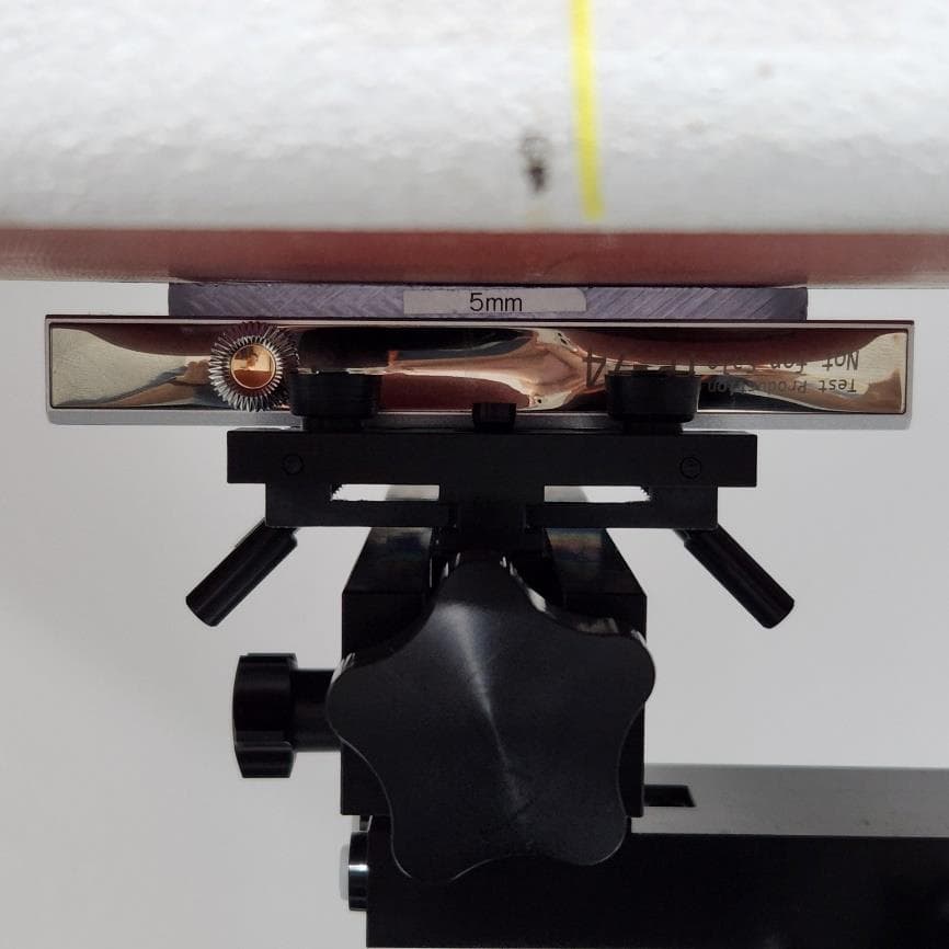
QDMPPR51
May 07, 2023SE300
Equipment Class
NII - Unlicensed National Information Infrastructure TX
QDM-HERO-OLS01
Jan 16, 2023LIM YOUNG WOONG OFFICIAL LIGHT STICK
Equipment Class
DTS - Digital Transmission System
QDMPPR42
Dec 07, 2022ACRO CA1000T
Equipment Class
DSS - Part 15 Spread Spectrum Transmitter