QDQ-100Wireless mask communicator for firemen
Safety Tech Industries Inc
Click to zoom
Application Details
- Equipment Class
- FRF - Part 95 Family Radio Face Held Transmitter
- Date of Grant
- Jul 30, 2002
- Application Purpose
- Original Equipment
- Date of Application
- May 19, 2002
- Equipment Note
- Wireless mask communicator for firemen
- Frequency Range
- 467.66250000 - 467.71250000
- Company
- Safety Tech Industries Inc
- Country
- United States
Documents & Files

Document Text
Text extracted from the exhibit documents filed with the FCC. Open a document above to read the original.
Users Manual
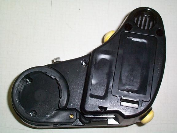
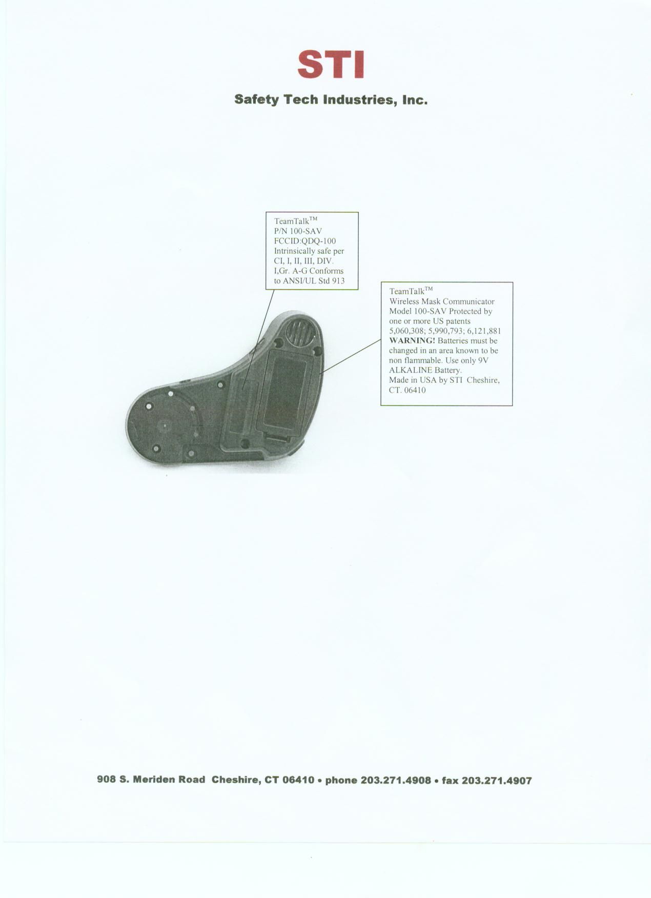
Draft version – 1.21 04/01/02 TeamTalk ™ Model 100-SAV WIRELESS SCBA MASK COMMUNICATORS For the Scott ® AV-2000 Facepiece Manufactured by:Distributed by: Safety Tech Industries, Inc.Survival Counts, Inc. 908 S. Meriden RoadP.O. Box 911 Cheshire, CT 06410Middletown, MD 21769 (800) 996-1942(301) 371-3000 www.safetytechindustries.comwww.survivalcounts.com TeamTalk TM 2 Table of Contents Page General Description3 Attaching The TeamTalk TM Mask Communicator To Your Face Piece6 Using The TeamTalk TM Mask Communicator11 Volume Control13 Warranty14 Repair Of Damaged Units14 Product Specifications15 Frequently Asked Questions17 Contact and Ordering Information21 On-Site Demonstrations21 TeamTalk TM 3 T EAM T ALK TM Model 100-SAV Wireless SCBA Mask Communicator GENERAL DESCRIPTION TeamTalk TM mask communicators are designed to provide wireless communications among members of a fire fighting team (or other team involved in operations in a hazardous environment) while wearing Scott ® Airpacks equipped with the AV-2000™ facepiece. The TeamTalk TM assembly attaches to the right voice emitter of the AV- 2000™ face-piece by means of a cam locking mechanism. When properly attached to the right voice emitter, TeamTalk TM will pick up voice sounds spoken by the wearer and transmit the sound to other TeamTalk TM units within a range of at least 400 feet (line-of- site) by engagement of a push-to-talk (PTT) button. The TeamTalk TM mask communicator’s speaker is located directly near the wearer’s right ear providing clear, unobstructed sound. TeamTalk TM is also equipped with two buttons to raise and lower speaker volume. F IGURE 1 Outside View of the TeamTalk TM Un it T Volume Up Button LED Indicator Push-To-Talk Button “On” and Volume Down Button Front Edge Channel Indicator Label Rear Edge TeamTalk TM 4 eamTalk TM provides eight factory pre-set channels. Different teams can be assigned separate channels to avoid cross talking between the teams. TeamTalk TM also has an alternate channel that can be selected while the mask communicator is in use. This allows a user to speak directly to members of other teams so long as they are also on the alternate channel. F IGURE 2 Back of TeamTalk TM Unit List of Equipment Features ItemDescription LED Indicator LightThis is a multiple function item. It will flash briefly when the TeamTalk TM mask communicator is first turned on; it will light up when you are transmitting; and it will stay on when the alternate channel is selected. In the alternate channel, the LED goes out to indicate you are transmitting. Volume UP ButtonThis round yellow button on the top edge of the TeamTalk TM mask communicator enables the user to easily raise the volume by a series of presses on the button. Each press of the button will increase volume approximately 10 decibels to a maximum of 100 decibels. Mounting Groove Mounting Clamp Waterproof Speaker Waterproof Microphone Locking Lever Battery compartment Inside View TeamTalk TM 5 “ON” and Volume DOWN Button This round yellow button is located on the bottom edge of the TeamTalk TM mask communicator and performs several functions. When the TeamTalk TM mask communicator is “OFF”, the user can turn it on by pressing and holding the button until he/she sees the LED indicator light flash and hears a brief transmission. After the unit has been turned “ON”, this button enables the user to easily lower the volume by a series of presses on the button. Each press will lower the volume approximately 10 decibels. When pressed and held simultaneously with the Volume Up button, it will enable the user to switch to or from the “alternate” channel. Channel Indicator Label This label is applied by the factory to indicate which channel the TeamTalk TM mask communicator has been set (Channels 1 through 8). It is numbered and color-coded to give easy recognition to the preset channel. Push-to-Talk ButtonAlso called the PTT button, this large yellow pad is easily pressed and held when the user wants to transmit to other users. MicrophoneThe waterproof microphone is located directly over the right voice emitter. SpeakerLocated directly over your right ear, the waterproof speaker provides clear transmission of messages. Battery compartmentLocated on the back of the TeamTalk TM mask communicator, the battery compartment holds a 9-volt battery. Mounting groove The mounting groove slides over the frame of the Scott AV-2000 TM facemask to provide stability to the TeamTa lk TM mask communicator. Locking leverThis lever forces open the mounting clamp when attaching the unit to the facemask and then closes to securely lock the mounting clamp onto the voice emitter. Mounting clampThe mounting clamp goes around the voice emitter to securely attach the TeamTalk TM mask communicator to the facemask. TeamTalk TM 6 ATTACHING THE TEAMTALK TM MASK COMMUNICATOR TO YOUR FACE PIECE F IGURE 3 Scott AV-2000 TM Face Mask The TeamTalk TM mask communicator attaches to the voice emitter on the right side of the Scott AV-2000 TM face-piece (See Figure 3). Prior to attaching the mask communicator, inspect it for exterior damage. If any damage is found do not use the mask communicator; tag it for repair and remove from service. To attach and secure the unit to the facepiece please follow the steps below as shown in Figures 4 through 9. 1. Hold the TeamTalk TM unit in your right hand so that the large yellow Push-To-Talk button is in your right palm. Open the lever 90° and hold it wide open using your right middle finger. F IGURE 4 TeamTalk TM attaches to the right side of the mask and the right voice emitter TeamTalk TM 7 F IGURE 5 2. Hold the Scott AV-2000 TM face-piece in your left hand (Figure 5) by placing your thumb in the respirator opening and wrapping your fingers under the chin of the mask. 3. Use your left index finger to hold the right chin adjustment strap out of the way. TeamTalk TM 8 F IGURE 6 4. While still holding the lever wide open, slide the right edge of the facep…
Text truncated - open the document above for the full version.
Operational Description
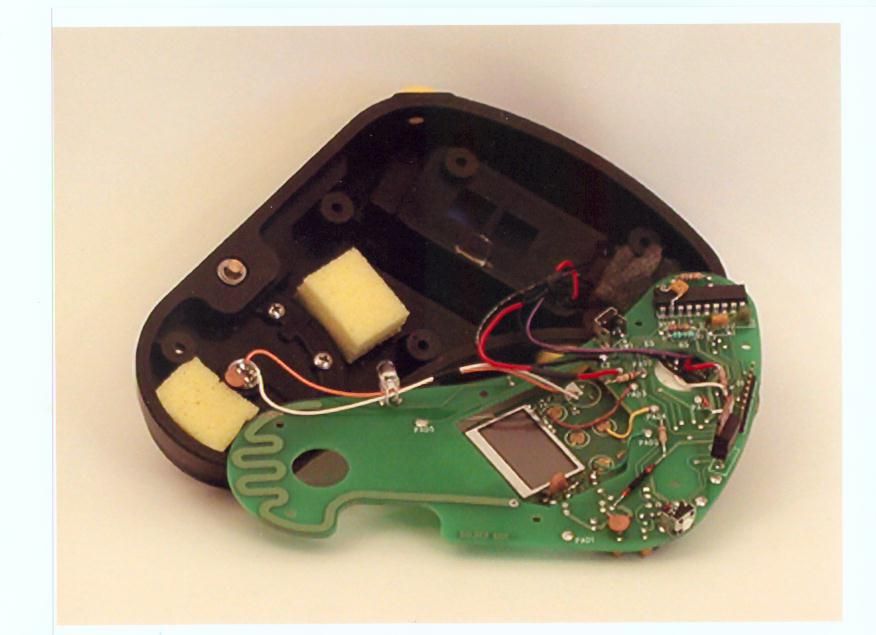
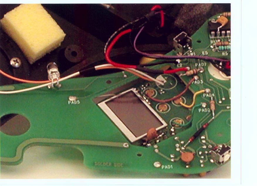
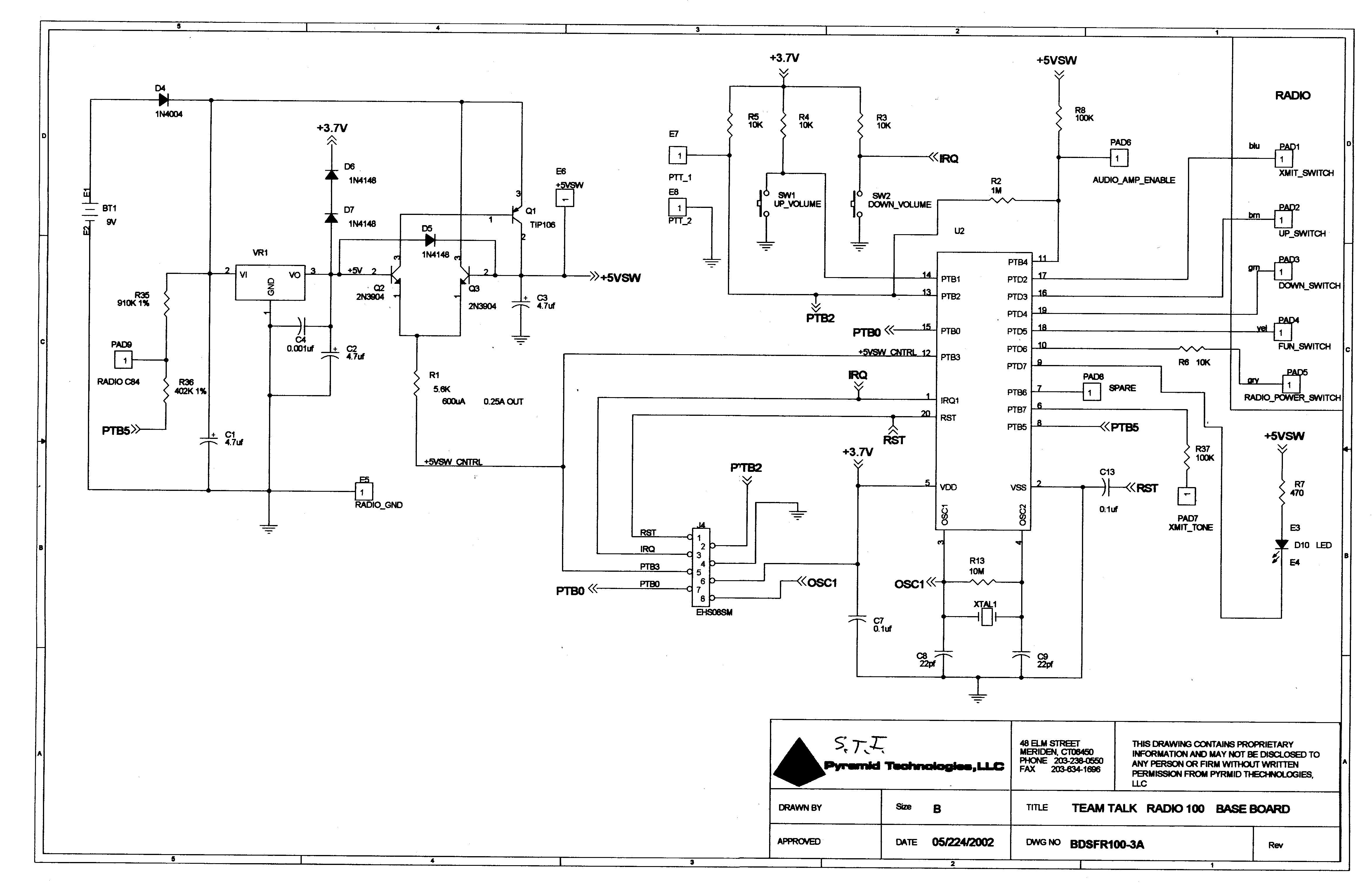
INTRODUCTION & COVER LETTER Because the device described in FCCID: QDQ-100 uses an already approved FRS radio core in a new application, more explanation is warranted. The original FRS core that will be used in this device has FCC ID: PHC-1428. The grant was given on 6/12/2001. This new device is a special purpose transceiver that is to be used by firefighters and other rescue services for short-range communications during fires, or any usage requiring a breathing air mask. It uses a side-of-head mounted triangular housing. This housing allows the microphone to be placed on the facemask’s voice diaphragm, and repositions the speaker over the ear. The extra circuitry made/assembled by the manufacturer (Safety Tech Industries) is completely contained in the housing. It will be marketed as the model SAV-100 “TeamTalk”. Simple “push-to-talk”, “on/off” and volume controls are done by three push buttons. The interface between the buttons and the PHC-1428 FRS-radio core is achieved by extra circuitry. The device manufacturer will supply the description of this (see enclosed), and all other circuitry in the exhibits. Because of the availability of 9-volt alkaline batteries to fire personnel, a separate voltage regulator is used to lower the 9-volt level to a 5-volt level to operate the PHC-1428. The transceiver emits a distinctive double beep when battery voltage drops below 7 volts. Once the beeping begins, there are 30 minutes of operation time available. The transceiver complies with the “5%Transmit, 5%Receive, 90% standby” standard for portable transceivers. There is no provision for the recharging of batteries. A 47-ohm resistor at the RF output of the radio board and a printed circuit antenna reduce the output power from the PHC-1428. Because of this new antenna system, effective radiated power and spurious radiated emission measurements are included in the exhibits. The effective power level is reduced from the 300mW level described in the PHC-1428 level. Only short-range communications are needed for this device and the higher power to be reduced for this application. For operational simplicity, only two out of the 14 channels present in the PHC-1428 are used. One assigned channel is for normal usage. The second channel is used for special needs, such as mutual aid from other cities or departments. This “alternate” channel is selected by the simultaneous pushing on both up & down volume buttons for 3 seconds. The unit returns to the regular channel upon either repeating the dual buttons, or a powering down (off) of the unit. The selection of what channel is to be “normal” is up to each customer, however, it is programmed to that channel by Safety Tech Industries. The upper pushbutton is used to increase the speaker volume in eight distinct steps. The lower pushbutton lowers the speaker volume, but does not allow the volume to go totally “off”. The manufacturer affects no RF generating subsystem of the PHC-1428 core. The PHC-1428 core is bought in quantity and no on-board functions are changed. For this reason, the frequency stability due to temperature and battery voltage variations, bandwidth and modulation tests are not repeated. The original unit is used as was designed. Safety Tech Industries merely has employed a different method to control the original pushbuttons on the radio core’s PCB board. Thank you, for your time and effort in this project. If there is anything else you need beyond the exhibits submitted, please contact via email or by the following: Stephen M. Petix Global Certification Laboratory, 4 Matthews Dr. East Haddam, CT. 06423 Tel: (860) 873-1452 Fax: (860) 873-1947
Test Report
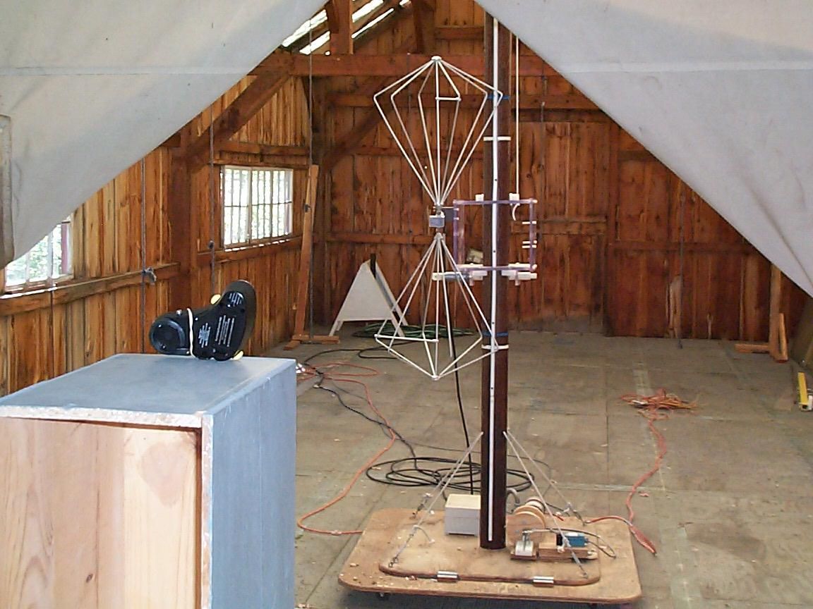
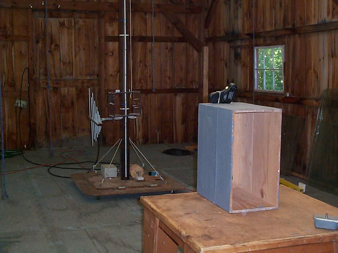
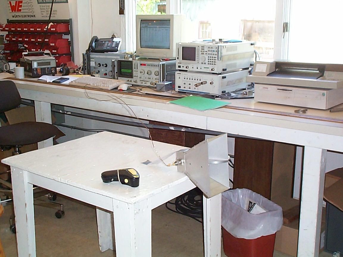
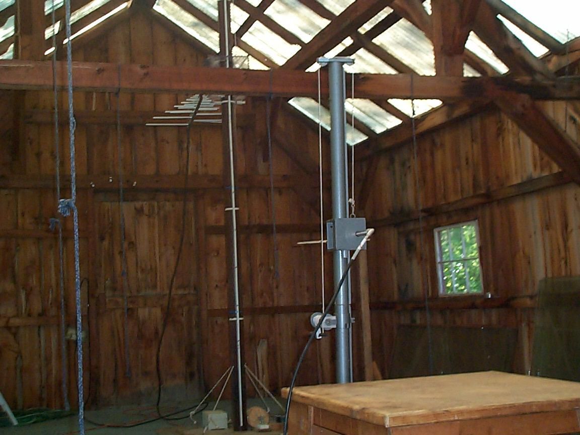
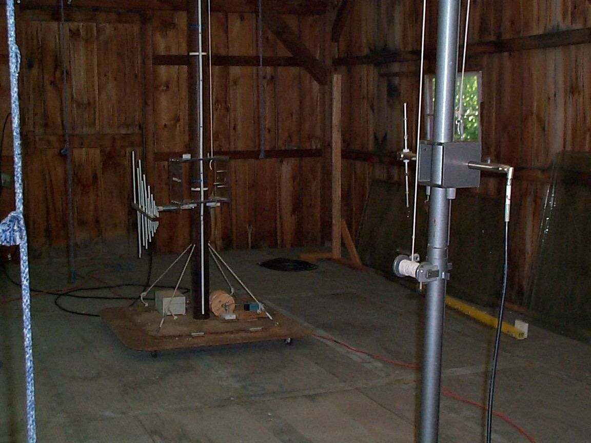
FILE NAME: SAF0201 EUT NAME: "Team Talk" SAV-100 THE EUT IS A REDUCED POWER, FRS-BASED TRANSCEIVER. IT IS POWERED BY A SINGLE 9VDC ALKALINE BATTERY. THE EUT IS A PROTOTYPE, USE SERIAL NUMBER: " PROTO1." CUSTOMER REPRESENTATIVE: CURT SEATON (not present) MEASURED BY STEVE PETIX ON 5/22/02 TO FCC PART 95 USING 3 METER OPEN AREA TEST SITES, (OATS). THE EUT MEASURING ANTENNAS ARE: A SCHWARZBECK MODEL VHA9103 BICONICAL ANTENNA, (s/n: A) IS USED FOR 30 TO 300 MHz. AN AILTECH MODEL 96005, (s/n 1095), LOG PERIODIC ANTENNA IS USED FOR 300 TO 1000 MHz. AN EMCO MODEL 3115 s/n 2498 GUIDED RIDGE HORN ANTENNA IS USED FOR 1 TO 18 GHz. THE SUBSTITUTION ANTENNAS IS: A SCHWARZBECK MODEL UHA-9105 TUNED DIPOLE IS USED FOR 300 TO 1000 MHz. THE ANTENNAS ARE FACING THE YELLOW TRANSMIT BUTTON SIDE FOR ALL MEASUREMENTS. THE EUT IS 1.5 METERS ABOVE THE SHEET STEEL GROUND PLANE. ALL MEASUREMENTS USE PEAK DETECTION. ADVANTEST MODEL R3361A & HP MODEL 8569B SPECTRUM ANALYZERS ARE USED. The EUT is based on a previously approved FRS radio core. Its FCC ID is: PHC-1428. This FRS radio core is used in the Audiovox model FR-1428 Two Way Family Radio. It is manufactured by Linkomm Communications Network of South Korea. Safety Tech Industries, Inc. is using this FRS radio core electronically unchanged. It places the radio core inside a new housing that is to be mounted on the face mask of firefighters. The housing contains circuitry on a mother board that interfaces with the FR-1428's controls. This circuitry allows the use of any of the 14 channels. Safety Tech Industries elected to use channel 12 (467.6625MHz) for a "common" channel on all units. The only RF modification is the use of a PCB antenna with a 47 ohm loading resistor mounted on the interface electronics board. The PCB antenna and load resistor reduce the effective radiated power from the 300 milliwatts claimed by Linkomm Communications for the PHC-148 radio core. In this unit, Channel, 467.714 MHz, is used for all measurements. All measurements are performed with the bottom edge of the TeamTalk housing parallel to the ground. This is similar to its actual orientation on the firefighter's face mask when he/she is looking straight ahead. The TeamTalk FCC ID is: QDQ-100. continued on next page TEST & MEASUREMENT DATA REPORT FOR "TEAM TALK" TRANSCEIVER CARRIER FIELD STRENGTH MEASUREMENTS: The EUT's unmodulated carrier is measured on a spectrum analyzer. The maximum level is measured by scanning the receive antenna height from 1 to 4 meters. No preamplifier is used at the spectrum analyzer input. No amplifier is used at the signal generator output. THE 300 TO 1000MHz ANTENNA IS VERTICAL FREQ. (MHz) AMPL QUASI-P dB(μ μμ μV) CABLE LOSS, dB ANTENNA FACTORS dB/m TOTAL FIELD dB(μ μμ μV/m) 467.714794.4416.88100.32 THE 300 TO 1000MHz ANTENNA IS HORIZONTAL FREQ. (MHz) AMPL QUASI-P dB(μ μμ μV) CABLE LOSS, dB ANTENNA FACTORS dB/m TOTAL FIELD dB(μ μμ μV/m) 467.714874.4416.88108.32 Sections 2.1046 (a) & 95.639: RF POWER OUTPUT: The EUT is replaced with the tuned dipole antenna located in the exact position the EUT was for the measurements above. The dipole is energized with a Marconi model 2022C signal generator. Due to insufficient power, a 32 dB preamplifier on the spectrum analyzer input was needed to boost the signal from the receive antenna. The output of the signal generator was raised until the resulting 467.714MHz signal level matched the level recorded from the field strength measurement above. THE 300 TO 1000MHz SUBSTITUTION DIPOLE IS VERTICAL. FREQ. (MHz) LENGTH OF EACH DIPOLE AERIAL (mm) MATCH SIG GEN OUTPUT (dBm) LAB to OATS REF ANT CABLE LOSS (dB) DIPOLE ANTENNA. GAIN (dBi) R14601 PREAMP GAIN (dB) EFFECTIVE RADIATED POWER (dBm) EFFECTIVE RADIATED POWER (mw) 467.711155.00-24.004.72.20325.503.55 THE 300 TO 1000MHz SUBSTITUTION DIPOLE IS HORIZONTAL. FREQ. (MHz) LENGTH OF EACH DIPOLE AERIAL (mm) MATCH SIG GEN OUTPUT (dBm) LAB to OATS REF ANT CABLE LOSS (dB) DIPOLE ANTENNA. GAIN (dBi) R14601 PREAMP GAIN (dB) EFFECTIVE RADIATED POWER (dBm) EFFECTIVE RADIATED POWER (mw) 467.711155.00-13.004.72.203216.5044.67 Using the higher power rating from the horizontal measurements, the emission mask formula; 43 + 10log(P), with P = .04467 watts, yields 29.5 dB. This is the level spurious emissions need to be attenuated by, relative to the carrier. continued on next page Sections 2.1053 and 95.635(b) (4): SPURIOUS EMISSIONS MEASUREMENTS: The following measurements are of spurious emissions that appear only when the transmitter is activated. "Atten Below Max Carrier Level" = 108 - "Total Field". "Margin" = 29.5 - "Atten Below Carrier". FREQ. (MHz) AMPL dB(μ μμ μV) CABLE LOSS, dB ANTENNA FACTORS dB/m TOTAL FIELD dB(μ μμ μV/m) ATTEN BELOW MAX CARRIER LEVEL PASS? (YES) MARGIN dB FREQ. (MHz) AMPL dB(μ μμ μV) CABLE LOSS, dB ANTENNA FACTORS dB/m TOTAL FIELD dB(μ μμ μV/m) ATTEN BELOW MAX CARRIER LEVEL PASS? (YES) MARGIN dB THE 300 TO 1000MHz ANTENNA IS HORIZONTAL & AT 3 METERS. FREQ. (MHz) AMPL dB(μ μμ μV) CABLE LOSS, dB ANTENNA FACTORS dB/m TOTAL FIELD dB(μ μμ μV/m) ATTEN BELOW MAX CARRIER LEVEL PASS? MARGIN dB 935.9003813.0823.1974.2733.73YES4.23 NO OTHER SIGNIFICANT EUT SIGNALS FOUND FOR THIS RANGE. THE 300 TO 1000MHz ANTENNA IS VERTICAL & AT 3 METERS. FREQ. (MHz) AMPL dB(μ μμ μV) CABLE LOSS, dB ANTENNA FACTORS dB/m TOTAL FIELD dB(μ μμ μV/m) ATTEN BELOW MAX CARRIER LEVEL PASS? MARGIN dB 935.9001113.0823.1947.2760.73YES31.23 NO OTHER SIGNIFICANT EUT SIGNALS FOUND FOR THIS RANGE. continued on next page NO SIGNIFICANT EUT SIGNALS FOUND FOR THIS RANGE. THE 30 TO 300 MHz ANTENNA IS VERTICAL AND AT 3 METERS. NO SIGNIFICANT EUT SIGNALS FOUND FOR THIS RANGE. THE 30 TO 300 MHz ANTENNA IS HORIZONTAL & AT 3 METERS. THE 1 TO 18 GHz ANTENNA IS VERTICAL AND AT 3 METERS. FREQ. (MHz) AMPL dBm AMPL dBuV CABLE LOSS dB HORN ANTENNA FACTOR TOTAL FIELD (dBuV/m) ATTEN BELOW MAX CARRIER LEVEL PASS? MARGIN (dBμ μμ μV) 14060.001070.0025.76133-24.76NO54.26 1871-84230.0027.55157.50YES28.00 2339-78291.0028.625949.…
Text truncated - open the document above for the full version.
Test Report
TABLE OF CONTENTS LIST APPLICANT: LINKOMM COMMUNICATION NETWORK FCC ID: PHC1428 TEST REPORT: PAGE 1......COVER SHEET - GENERAL INFORMATION & TECHNICAL DESCR. PAGE 2......TECHNICAL DESCRIPTION CONTINUED & RF POWER OUTPUT PAGE 3......MODULATION CHARACTERISTICS AND OCCUPIED BANDWIDTH PAGE 4......METHOD OF MEASURING OCCUPIED BANDWIDTH PAGE 5......FIELD STRENGTH OF SPURIOUS EMISSIONS PAGE 6......METHOD OF MEASURING RADIATED SPURIOUS EMISSIONS PAGE 7......FREQUENCY STABILITY PAGE 8......LIST OF TEST EQUIPMENT EXHIBITS CONTAINING: EXHIBIT 1.........FCC ID LABEL SAMPLE EXHIBIT 2.........SKETCH OF FCC ID LABEL LOCATION EXHIBIT 3A........EXTERNAL PHOTO - FRONT VIEW EXHIBIT 3B........EXTERNAL PHOTO - TOP VIEW EXHIBIT 3C........EXTERNAL PHOTO - BOTTOM EXHIBIT 3D-3E.....EXTERNAL PHOTO - SIDE VIEW EXHIBIT 3F........EXTERNAL PHOTO - REAR VIEW EXHIBIT 3G........INTERNAL PHOTO - SOLDER SIDE EXHIBIT 3H........INTERNAL PHOTO - COMPONENT SIDE EXHIBIT 4.........BLOCK DIAGRAM EXHIBIT 5A-5B.....SCHEMATIC EXHIBIT 6A-6G.....USER'S MANUAL EXHIBIT 7A-7B.....CIRCUIT DESCRIPTION EXHIBIT 8.........AUDIO FREQUENCY RESPONSE GRAPH EXHIBIT 9A........MODULATION LIMITING PLOT - 300 Hz EXHIBIT 9B........MODULATION LIMITING PLOT - 1000 Hz EXHIBIT 9C........MODULATION LIMITING PLOT - 3000 Hz EXHIBIT 10........AUDIO LOW PASS FILTER GRAPH EXHIBIT 11A.......OCCUPIED BANDWIDTH CW PLOT EXHIBIT 11B.......OCCUPIED BANDWIDTH PLOT APPLICANT: LINKOMM COMMUNICATION NETWORK FCC ID: PHC1428 REPORT #: T:\CUS\L\LINKOMM\246ZK1\246zk1rpt.doc PAGE: TABLE OF CONTENTS GENERAL_INFORMATION_REQUIRED FOR_TYPE_ACCEPTANCE 2.1033(c)(1)(2) LINKOMM COMMUNICATION NETWORK will manufacture the FCCID: PHC1428 FAMILY RADIO SERVICES 14 CHANNEL TRANSCEIVER in quantity, for use under FCC RULES PART 95. The UUT is a PTT Radio with a maximum duty cycle of 50%. LINKOMM COMMUNICATION NETWORK SAMYOUNG B/D, 48-8 SHINWOUL, 3-DONG, YANCHEON-GU SEOUL, KOREA 2.1033 (c) TECHNICAL_DESCRIPTION 2.1033(c)(3) Instruction book. A draft copy of the instruction manual is included as EXHIBIT 6A-6J. 2.1033(c) (4) Type of Emission: 10K6F3E 95.631 Bn = 2M + 2DK M = 3000 D = 2.0K Bn = 2(3.0)+2(2.3) = 10.6K Authorized Bandwidth 12.5KHz 2.1033(c)(5) Frequency Range: 1. 462.5625 8. 467.5625 95.627 2. 462.5875 9. 467.5875 3. 462.6125 10. 467.6125 4. 462.6375 11. 467.6375 5. 462.6625 12. 467.6625 6. 462.6875 13. 467.6875 7. 462.7125 14. 467.7125 MHz 2.1033(c)(6)(7) Power Output shall not exceed 0.500Watts effective 95.639 radiated power. There can be no provisions for 95.649 increasing the power or varing the power. The Maximum Output Power Rating: 300 milliWatts effective radiated power. 95.647 The antenna is an intergral part to the unit, it cannot be removed without rendering the unit inoperative. In order to remove the antenna the case must unscrewed, then the PCB assemblies must be removed then the antenna can be removed. 2.1033(c)(8) DC Voltages and Current into Final Amplifier: FINAL AMPLIFIER ONLY Vce = 6.0 Volts DC Ice = 0.25A. Pin = 1.5 Watts REPORT #: T:\CUS\L\LINKOMM\246ZK1\246zk1rpt.doc PAGE #: 1 2.1033(c)(9) Tune-up procedure. The tune-up procedure is included in the IN USER'S MANUAL. 2.1033(c)(10) Complete Circuit Diagrams: The circuit diagram is included as EXHIBIT 5 of this report. The block diagram is included as EXHIBIT 4 of this report. 2.1033(c)(11) A photograph or a drawing of the equipment identifica tion label is included as exhibit No. 2. 2.1033(c)(12) Photographs(8"X10") of the equipment of sufficient clarity to reveal equipment construction and layout, including meters, labels for controls, including any view under shields - See EXHIBIT 3A-3H. 2.1033(c)(13) Digital modulation is not allowed. 2.1033(c)(14) The data required by 2.1046 through 2.1057 is submitted below. 2.1046(a) RF_power_output. 95.639 RF power is measured by measuring the radiated power at 3 meters and then replacing the transmitter with a signal generator to determine the effective radiated power. The ERP shall not exceed 0.500 Watts. MEASURED POWER OUTPUT = 300 milliWatts ERP R.F. POWER OUTPUT HP TEST SET UP Spectrum Analyzer /-------\ /-----------------\ | | | | TRANSMITTER | | | | | UNDER TEST WITH | \--| | | INTERNAL ANTENNA| | | | \-----------------/ | | | | | \-------/ | | |<-- 3.0 meters-->| /-------------\ | SIGNAL | DIPOLE | Tuned, Calibrated | GENERATOR | ANTENNA | Antenna which may | |----------/ be raised from 1 \-------------/ to 4 meters above ground and changed in polarization Equipment placed 80cm above ground on a rotatable platform. REPORT #: T:\CUS\L\LINKOMM\246ZK1\246zk1rpt.doc PAGE #: 2 2.1047(a)(b) Modulation_characteristics: AUDIO_FREQUENCY_RESPONSE The audio frequency response was measured in ac- cordance with TIA/EIA Specification 603. The audio frequency response curve is shown in exhibit 8. The audio signal was fed into a dummy microphone circuit and into the microphone connector. The input required to produce 30 percent modulation level was measured. 2.1047(b) Audio_input_versus_modulation The audio input level needed for a particular per- percentage of modulation was measured in accor- dance with TIA/EIA Specification 603. The audio input curves versus modulation are shown in exhibits 9A - 9C. Curves are provided for audio input frequen cies of 300, 1000, and 3000 Hz. 95.637(b) Post Limiter Filter The filter must be between the modulation limiter and the modulated stage. At any frequency between 3 & 20KHz the filter must have an attenuation of 60log (f/3) greater that the attenuation at 1KHz. See the plot; exhibit 10. 2.989(c) EMISSION BANDWIDTH: 95.633(c) Data in the plots shows that the sidebands from greater than 50% to 100% of the authorized bandwidth must be attenuated by at least 25dB and from 100 to 250% the sidebands must be attenuated by at least 35dB. Beyond 250% the sidebands must be attenuated by at least 43+log10(TP). The transmitter was modulated with 2500 Hz, adjusted for 50% modulation plus 16 dB. The spectrum analyzer was set with the unmodulated carri…
Text truncated - open the document above for the full version.
Test Report
Modulation Limiting Linkomm Comm. PHC1428 0 200 400 600 800 1000 1200 0510152025 rms mVolts Deviation 3000 Hz LINKOMM COMMUNICATION NETWORK FCC ID: PHC1428 JOB #: 246ZK1 EXHIBIT #: 9C
Test Report
Modulation Limiting Linkomm Comm. PHC1428 0 500 1000 1500 2000 2500 0 1020304050 rms mVolts Deviation 300 Hz LINKOMM COMMUNICATION NETWORK FCC ID: PHC1428 JOB #: 246ZK1 EXHIBIT #: 9A
Test Report
Linkomm Comm. PHC1428 0 10 20 30 40 50 60 100100010000 Freque ncy rms mVolts audio response LINKOMM COMMUNICATION NETWORK FCC ID: PHC1428 JOB #: 246ZK1 EXHIBIT #: 8
Test Report
FILE NAME: SAF0201 EUT NAME: "Team Talk" SAV-100 THE EUT IS A REDUCED POWER, FRS-BASED TRANSCEIVER. IT IS POWERED BY A SINGLE 9VDC ALKALINE BATTERY. THE EUT IS A PROTOTYPE, USE SERIAL NUMBER: " PROTO1." CUSTOMER REPRESENTATIVE: CURT SEATON (not present) MEASURED BY STEVE PETIX ON 5/22/02 TO FCC PART 95 USING 3 METER OPEN AREA TEST SITES, (OATS). THE EUT MEASURING ANTENNAS ARE: A SCHWARZBECK MODEL VHA9103 BICONICAL ANTENNA, (s/n: A) IS USED FOR 30 TO 300 MHz. AN AILTECH MODEL 96005, (s/n 1095), LOG PERIODIC ANTENNA IS USED FOR 300 TO 1000 MHz. AN EMCO MODEL 3115 s/n 2498 GUIDED RIDGE HORN ANTENNA IS USED FOR 1 TO 18 GHz. THE SUBSTITUTION ANTENNAS IS: A SCHWARZBECK MODEL UHA-9105 TUNED DIPOLE IS USED FOR 300 TO 1000 MHz. THE ANTENNAS ARE FACING THE YELLOW TRANSMIT BUTTON SIDE FOR ALL MEASUREMENTS. THE EUT IS 1.5 METERS ABOVE THE SHEET STEEL GROUND PLANE. ALL MEASUREMENTS USE PEAK DETECTION. ADVANTEST MODEL R3361A & HP MODEL 8569B SPECTRUM ANALYZERS ARE USED. The EUT is based on a previously approved FRS radio core. Its FCC ID is: PHC-1428. This FRS radio core is used in the Audiovox model FR-1428 Two Way Family Radio. It is manufactured by Linkomm Communications Network of South Korea. Safety Tech Industries, Inc. is using this FRS radio core electronically unchanged. It places the radio core inside a new housing that is to be mounted on the face mask of firefighters. The housing contains circuitry on a mother board that interfaces with the FR-1428's controls. This circuitry allows the use of any of the 14 channels. Safety Tech Industries elected to use channel 12 (467.6625MHz) for a "common" channel on all units. The only RF modification is the use of a PCB antenna with a 47 ohm loading resistor mounted on the interface electronics board. The PCB antenna and load resistor reduce the effective radiated power from the 300 milliwatts claimed by Linkomm Communications for the PHC-148 radio core. In this unit, Channel, 467.714 MHz, is used for all measurements. All measurements are performed with the bottom edge of the TeamTalk housing parallel to the ground. This is similar to its actual orientation on the firefighter's face mask when he/she is looking straight ahead. The TeamTalk FCC ID is: QDQ-100. continued on next page TEST & MEASUREMENT DATA REPORT FOR "TEAM TALK" TRANSCEIVER CARRIER FIELD STRENGTH MEASUREMENTS: The EUT's unmodulated carrier is measured on a spectrum analyzer. The maximum level is measured by scanning the receive antenna height from 1 to 4 meters. No preamplifier is used at the spectrum analyzer input. No amplifier is used at the signal generator output. THE 300 TO 1000MHz ANTENNA IS VERTICAL FREQ. (MHz) AMPL QUASI-P dB(μ μμ μV) CABLE LOSS, dB ANTENNA FACTORS dB/m TOTAL FIELD dB(μ μμ μV/m) 467.714794.4416.88100.32 THE 300 TO 1000MHz ANTENNA IS HORIZONTAL FREQ. (MHz) AMPL QUASI-P dB(μ μμ μV) CABLE LOSS, dB ANTENNA FACTORS dB/m TOTAL FIELD dB(μ μμ μV/m) 467.714874.4416.88108.32 Sections 2.1046 (a) & 95.639: RF POWER OUTPUT: The EUT is replaced with the tuned dipole antenna located in the exact position the EUT was for the measurements above. The dipole is energized with a Marconi model 2022C signal generator. Due to insufficient power, a 32 dB preamplifier on the spectrum analyzer input was needed to boost the signal from the receive antenna. The output of the signal generator was raised until the resulting 467.714MHz signal level matched the level recorded from the field strength measurement above. THE 300 TO 1000MHz SUBSTITUTION DIPOLE IS VERTICAL. FREQ. (MHz) LENGTH OF EACH DIPOLE AERIAL (mm) MATCH SIG GEN OUTPUT (dBm) LAB to OATS REF ANT CABLE LOSS (dB) DIPOLE ANTENNA. GAIN (dBi) R14601 PREAMP GAIN (dB) EFFECTIVE RADIATED POWER (dBm) EFFECTIVE RADIATED POWER (mw) 467.711155.00-24.004.72.20325.503.55 THE 300 TO 1000MHz SUBSTITUTION DIPOLE IS HORIZONTAL. FREQ. (MHz) LENGTH OF EACH DIPOLE AERIAL (mm) MATCH SIG GEN OUTPUT (dBm) LAB to OATS REF ANT CABLE LOSS (dB) DIPOLE ANTENNA. GAIN (dBi) R14601 PREAMP GAIN (dB) EFFECTIVE RADIATED POWER (dBm) EFFECTIVE RADIATED POWER (mw) 467.711155.00-13.004.72.203216.5044.67 Using the higher power rating from the horizontal measurements, the emission mask formula; 43 + 10log(P), with P = .04467 watts, yields 29.5 dB. This is the level spurious emissions need to be attenuated by, relative to the carrier. continued on next page Sections 2.1053 and 95.635(b) (4): SPURIOUS EMISSIONS MEASUREMENTS: The following measurements are of spurious emissions that appear only when the transmitter is activated. "Atten Below Max Carrier Level" = 108 - "Total Field". "Margin" = 29.5 - "Atten Below Carrier". FREQ. (MHz) AMPL dB(μ μμ μV) CABLE LOSS, dB ANTENNA FACTORS dB/m TOTAL FIELD dB(μ μμ μV/m) ATTEN BELOW MAX CARRIER LEVEL PASS? (YES) MARGIN dB FREQ. (MHz) AMPL dB(μ μμ μV) CABLE LOSS, dB ANTENNA FACTORS dB/m TOTAL FIELD dB(μ μμ μV/m) ATTEN BELOW MAX CARRIER LEVEL PASS? (YES) MARGIN dB THE 300 TO 1000MHz ANTENNA IS HORIZONTAL & AT 3 METERS. FREQ. (MHz) AMPL dB(μ μμ μV) CABLE LOSS, dB ANTENNA FACTORS dB/m TOTAL FIELD dB(μ μμ μV/m) ATTEN BELOW MAX CARRIER LEVEL PASS? MARGIN dB 935.9003813.0823.1974.2733.73YES4.23 NO OTHER SIGNIFICANT EUT SIGNALS FOUND FOR THIS RANGE. THE 300 TO 1000MHz ANTENNA IS VERTICAL & AT 3 METERS. FREQ. (MHz) AMPL dB(μ μμ μV) CABLE LOSS, dB ANTENNA FACTORS dB/m TOTAL FIELD dB(μ μμ μV/m) ATTEN BELOW MAX CARRIER LEVEL PASS? MARGIN dB 935.9001113.0823.1947.2760.73YES31.23 NO OTHER SIGNIFICANT EUT SIGNALS FOUND FOR THIS RANGE. continued on next page NO SIGNIFICANT EUT SIGNALS FOUND FOR THIS RANGE. THE 30 TO 300 MHz ANTENNA IS VERTICAL AND AT 3 METERS. NO SIGNIFICANT EUT SIGNALS FOUND FOR THIS RANGE. THE 30 TO 300 MHz ANTENNA IS HORIZONTAL & AT 3 METERS. THE 1 TO 18 GHz ANTENNA IS VERTICAL AND AT 3 METERS. FREQ. (MHz) AMPL dBm AMPL dBuV CABLE LOSS dB HORN ANTENNA FACTOR TOTAL FIELD (dBuV/m) ATTEN BELOW MAX CARRIER LEVEL PASS? MARGIN (dBμ μμ μV) 1406-56510.0025.767731.24YES1.74 1871-84230.0027.55157.50YES28.00 2339-78291.0028.625949.38YE…
Text truncated - open the document above for the full version.
Contact Information
Applicant
Curt Seaton(VP of Engineering)
Technical Contact
GLOBAL CERTIFICATION LABORATORYSTEPHEN M PETIX
[email protected](860) 873-1452
4 MATTHEWS DRIVE · EAST HADDAM, Connecticut · United States
Non-Technical Contact
GLOBAL CERTIFICATION LABORATORYJACK ROGERS
[email protected](860) 873-1451
Technical Specifications
| # | Rule Parts | Frequency Range | Power Output | Emission | Tolerance |
|---|---|---|---|---|---|
| 1 | 95B | 467.6625 MHz - 467.7125 MHz | 44.00 mW | 10K6F3E | 2.2000000000 ppm |