QE2-W320Emergency Pull Cord
Tel-Tron Technologies Corporation
Click to zoom
Application Details
- Equipment Class
- DSC - Part 15 Security/Remote Control Transmitter
- Date of Grant
- May 19, 2010
- Application Purpose
- Original Equipment
- Date of Application
- May 19, 2010
- Equipment Note
- Emergency Pull Cord
- Frequency Range
- 303.90000000 - 303.90000000
- Country
- United States
Documents & Files
Document Text
Text extracted from the exhibit documents filed with the FCC. Open a document above to read the original.
Users Manual
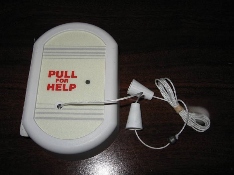
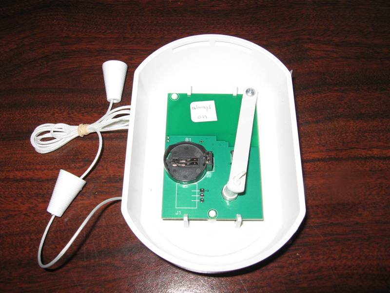
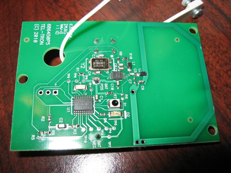
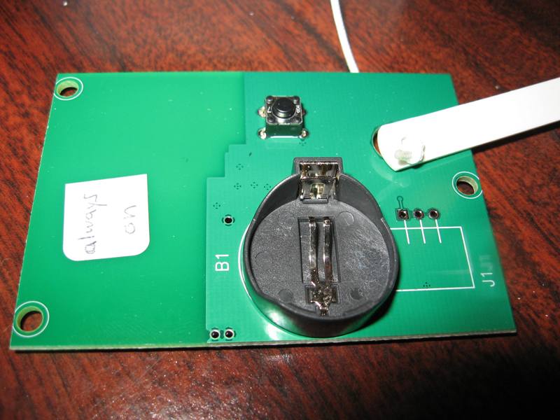
W320 Emergency Call Station Tel-Tron wireless call stations allow for wireless activation of an emergency call from anywhere within a resident’s apartment or community common areas. The W320 wireless call station mounts to the surface of any wall, creating a fixed location from which residents can call for help. The W320 has one pull cord for activation. When the cord is pulled, a mechanical linkage depresses an internal momentary push-button which causes the unit to transmit a 3-second series of repeated packets according to the protocol document referenced below. The W320 is useful in areas, such as bathrooms and bedrooms, where a pull cord reaching to the floor is desired. W320 Emergency Call Station © 2010 Tel-Tron Technologies Corporation - Doc.W320.0510 Dimensions 5” x 3.25” x 1.25” Mounting Requirements 1-Gang surface-mount plate requires either two #6 x 1” Pan Head Phillips screws (recommended) or double-sided tape. FCC ID: QE2-W320 This device complies with part 15 of the FCC rules. Operation is subject to the following two conditions: (1) This device may not cause harmful interference, and (2) this device must accept any interference received, including interference that may cause undesired operation. Tel-Tron Technologies Corporation 226 Fentress Boulevard Daytona Beach, FL 32114 P: (386) 255-1921 • F: (386) 258-3782 fyi.tel-tron.com [email protected] W320 Emergency Call Station © 2010 Tel-Tron Technologies Corporation - Doc.W320.0510 Specifications Carrier Frequency: 303.875MHz +/-200kHz. Emergency Call Carrier Duration: 3 Seconds. Packet Protocol: ASK, described in document SA802001_03. Continuous Pull Guard: If the cord is pulled continuously, the W320 will transmit for 3 seconds from the time of initiation, but will not transmit again until the cord is released and pulled again. Battery: CR2032 Lithium Coin Cell, 3V. Battery Life: At least 3 years of typical use, defined as one user-initiated activation each day at 25°C. Battery Monitoring: The W320 checks for a low battery every 4 hours with a constant carrier 30 ms load. If a low battery condition persists for 3 consecutive checks, the operating state switches to “low battery.” The operating state reverts to “normal” when power is removed and re-applied, or when the low-battery condition is not detected for 3 consecutive cycles. The W320 transmits a low-battery code (00) every 4 hours when the operating state is “low battery.” The W320 continues to function normally for at least 30 days after detection of a low-battery condition. LED Indicator: A single red LED that illuminates steadily when the W320 transmits normally. The LED flashes at a slow rate (less than 5Hz) while transmitting in a “low battery” operating state. Operating Environment: 0°C to 50°C in 10% to 90% relative humidity. Color: White. Modifications not expressly approved by the manufacturer could void the user’s authority to operated the equipment under FCC rules. Battery Linkage & internal button [Rear View] Pull cord
Cover Letter(s)
Letter of Agency I appoint Intertek Testing Services NA Inc. to act on our behalf in front of the Federal Communications Commission with respect to all matters relating to certification of equipment under the FCC rules until further notice. I further certify that no party (as defined in 1.2002 of CFR 47, 1995) to this application, including myself, is subject to denial of federal benefits, that includes FCC benefits, pursuant to Section 5301 of the Anti- Drug Abuse Act of 1988, 21 U.S.C.,853A. Equipment: W320 Emergency Call Station Dated this 14th day of April, 2010. Signature Buddy Krug___________________________ Name VP Engineering________________________ Tit le Tel-Tron Technologies___________________ Company 386-523-1070__________________________ Telephone 226 Fentress Boulevard Daytona Beach, Fl 32114 386.255.1921
Cover Letter(s)
April 14, 2010 Attention: Application Examiner Re: Request for confidentiality Applicant: Tel-Tron Technologies Corporation FCC ID: QE2-W320 To whom it may concern, Request is hereby submitted by Tel-Tron Technologies to withhold permanently from public review certain portions of the application for equipment certification for the referenced FCC identifiers. This request for confidentiality is made pursuant to 47 CFR 0.457(d) and 0.459 of the FCC Rules. In particular, the following sections of the application are to be kept permanently confidential: • Schematics • Detailed Block diagrams • Detailed Operational/Functional Descript ion Tel-Tron Technologies has invested considerable time and materials in research and development to produce the referenced product. Disclosure of the permanently confidential portions of this application to competitors would not only give them significant competitive advantages in developing similar products, but would also disclose successful implementation of unpublished, leading edge technology developed by us. The fee for confidentiality has been submitted along with the fee for certification. If you have questions or need further information, please contact the undersigned. Sincerely, Buddy Krug VP Engineering Tel-Tron Technologies, Inc. 226 Fentress Boulevard Daytona Beach, Fl 32114 386.255.1921
ID Label/Location Info
FCC ID Label & Location for W320 Emergency Call Station April 14, 2010 FCC ID: QE2-W320 The FCC ID label will be included with other product information on a single label and will be affixed to the back of the product casing as shown in the photograph below in Figure #1: Figure 1 226 Fentress Boulevard Daytona Beach, Fl 32114 386.255.1921
Test Report
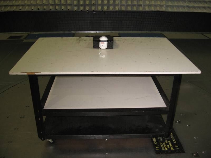
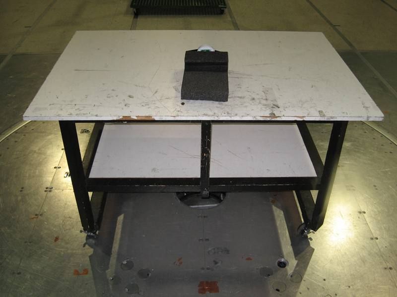
Client: Product Designation: W320 Emergency Pull Cord Report Number: 100088038ATL-001 All services undertaken are subject to the following general policy: This report is for the exclusive use of Intertek's Client and is provided pursuant to the agreement between Intertek and its Client. Intertek's responsibility and liability are limited to the terms and conditions of the agreement. Intertek assumes no liability to any party, other than to the Client in accordance with the agreement, for any loss, expense or damage occasioned by the use of this report. Only the Client is authorized to copy or distribute this report and then only in its entirety. Any use of the Intertek name or one of its marks for the sale or advertisement of the tested material, product or service must first be approved in writing by Intertek. The observations and test results in this report are relevant only to the sample tested. This report by itself does not imply that the material, product, or service is or has ever been under an Intertek certification program. This report must not be used to claim product endorsement by A2LA, NIST, or any agency of the US Government. Tested by: Tests performed by:Report reviewed by: Standard: Chris D. Capelle Senior Project Engineer Jeremy O. Pickens EMC Department Engineer Tel-Tron 220 Fentress Boulevard Daytona Beach, FL 32114 Contact: Buddy Krug Phone: 904.255.1921 Fax: 904.258.3782 TEST REPORT April 16, 2010 Intertek Testing Services NA Inc. 1950 Evergreen Blvd., Suite 100 Duluth, GA 30096 47 CFR Part 15, Subpart C (15.231 - Periodic operation in the band 40.66- 40.70 MHz and above 70 MHz) RSS-210, Issue 7, 2007 Page 1 of 23EMC Report for Tel-Tron on the W320 Emergency Pull Cord 04/16/2010Report Number: 100088038ATL-001Issued: Intertek 2.0 Test Summary 1.0 Introduction and Conclusion Test DateTest Full NameResultSection System setup including cable interconnection details, support equipment and simplified block diagram. (System Setup)4.0 Overview of EUT (Low Power Transmitters) (FCC 15C - EUT Overview)5.0 04/14/2010Restrictions (FCC 15C - 15.231(a))PASS6.0 04/14/2010Duty Cycle Determination (FCC 15A - 15.35(c))PASS7.0 04/14/2010Radiated Emissions (FCC 15C - 15.231(b))PASS8.0 04/14/2010Bandwidth Requirements (FCC 15C - 15.231(c))PASS9.0 Conducted emissions on AC power lines (Conducted Emissions) was waived due to the EUT is battery-powered.NA Conducted Emissions for Intentional Radiators (FCC 15C - 15.207) was waived due to the EUT is battery-powered.NA The tests indicated in section 2.0 were performed on the product constructed as described in section 3.0. The remaining test sections are the verbatum text from the actual data sheets used during the investigation. These test sections include the test name, the specified test Method, a list of the actual Test Equipment Used, documentation Photos, Results and raw Data. No additions, deviations, or exclusions have been made from the standard(s) unless specifically noted. Based on the results of our investigation, we have concluded the product tested complies with the requirements of the standard(s) indicated. The results obtained in this test report pertain only to the item(s) tested. Page 2 of 23EMC Report for Tel-Tron on the W320 Emergency Pull Cord 04/16/2010Report Number: 100088038ATL-001Issued: Intertek 3.0 Description of Equipment Under Test Equipment Under Test De scrip tio n Manufacturer Model Number Serial Number Emergency Pull Cord Tel-Tron Technologies Coporation W320 Not Labeled EUT receive date: 04/13/2010 EUT receive condition: Good Description of EUT provided by Client: The model W320 is an emergency pull cord for use in wireless health care applications. Description of EUT exercising: Upon inserting the battery, the EUT was powered and continuously transmitted as pre-set by the manufacturer. Page 3 of 23EMC Report for Tel-Tron on the W320 Emergency Pull Cord 04/16/2010Report Number: 100088038ATL-001Issued: Intertek System setup including cable interconnection details, support equipment and simplified block diagram. (System Setup) 4.0 Method: Record the details of EUTcabling, document the support equipment, and show the interconnections in a block diagram. EUT Block Diagram Drawing: Page 4 of 23EMC Report for Tel-Tron on the W320 Emergency Pull Cord 04/16/2010Report Number: 100088038ATL-001Issued: Intertek System setup including cable interconnection details, support equipment and simplified block diagram. (System Setup) 4.0 Description EUT Cabling Connection Length Shielding FerritesIDFromTo None None Support Equipment DescriptionManufacturerModel NumberSerial Number Data: Page 5 of 23EMC Report for Tel-Tron on the W320 Emergency Pull Cord 04/16/2010Report Number: 100088038ATL-001Issued: Intertek Overview of EUT (Low Power Transmitters) (FCC 15C - EUT Overview)5.0 Method: Complete the overview spreadsheet. Related Submittal(s) Grants: This report is for use with an application for certification of a low power transmitter. One transmitter is included in the application. Tel-Tron Technologies Corporation 220 Fen tres s Blvd . Day to na Beach, FL 32114 Trade Name / Model No. W320 FCC Identifier QE2-W320 Frequency Range (MHz) 303.9 A nten na Typ e (15.203) In teg ral Tel-Tron Technologies Corporation 220 Fen tres s Blvd . Day to na Beach, FL 32114 Additions, deviations and exclusions from standards This report is for use with an application for certification of a low power transmitter. One transmitter is included in the application. Applicant Manufacturer name & address Related Submittals and Grants: Data: Page 6 of 23EMC Report for Tel-Tron on the W320 Emergency Pull Cord 04/16/2010Report Number: 100088038ATL-001Issued: Intertek Restrictions (FCC 15C - 15.231(a))6.0 Method: 15.231(a) The provisions of this section are restricted to periodic operation within the band 40.66-40.70 MHz and above 70 MHz. Except as shown in paragraph (e) of this section, the intentional radiator is restricted to the transmission of a control…
Text truncated - open the document above for the full version.
Contact Information
Applicant
N. Rick Dawson(President)
Test Firm
Intertek Testing Services NA Inc.Charles Parker
Technical Specifications
| # | Rule Parts | Frequency Range | Power Output |
|---|---|---|---|
| 1 | 15.231 | 303.9 MHz - 303.9 MHz | - |
Other Applications from Tel-Tron Technologies Corporation

QE2-WECA
Aug 04, 2002Wireless Emergency Call Station
Equipment Class
DSC - Part 15 Security/Remote Control Transmitter