QEFNWTAP-100Wireless TAP
NETWAVE.CO., LTD.
Click to zoom
Application Details
- Equipment Class
- DTS - Digital Transmission System
- Date of Grant
- Mar 28, 2007
- Application Purpose
- Original Equipment
- Date of Application
- Mar 28, 2007
- Equipment Note
- Wireless TAP
- Frequency Range
- 2412.00000000 - 2462.00000000
- Company
- NETWAVE.CO., LTD.
- Country
- South Korea
Documents & Files
Document Text
Text extracted from the exhibit documents filed with the FCC. Open a document above to read the original.
Users Manual
NWTAP-100 user guide 1 Netwave Proprietary and Confidential NWTAP-100 Wireless Tap User Guide Preliminary Release 1.0, Issue 2 March 12, 2007 Netwave Co., Ltd. NWTAP-100 user guide 2 Netwave Proprietary and Confidential Contents 1. Overview ................................................................................................................... 3 1.1. Introduction........................................................................................................ 3 1.2. Product Description ........................................................................................... 4 2. Installation ............................................................................................................... 11 2.1. Unpacking and Content Checking ................................................................... 11 2.2. Remove Current Tap ....................................................................................... 12 2.3. Install the Wireless Tap ................................................................................... 12 2.4. Attach the Antenna .......................................................................................... 13 2.5. Insert the Power .............................................................................................. 14 2.6. Check for Proper Operation ............................................................................ 14 2.7. Performance Measurement ............................................................................. 16 3. WLAN Site Survey and Planning............................................................................. 17 3.1. Location ........................................................................................................... 17 3.2. Radio Link Path ............................................................................................... 17 3.3. RF Channel Selection ..................................................................................... 18 3.4. Performance check ......................................................................................... 18 4. Configuration ........................................................................................................... 19 4.1. Webui based configuration .............................................................................. 19 4.2. WIRELESS ...................................................................................................... 22 4.3. Wireless/Basic submenu ................................................................................. 23 4.4. Wireless/Security submenu ............................................................................. 23 4.5. Wireless/Access Control submenu.................................................................. 24 4.6. Wireless/Advanced submenu .......................................................................... 25 4.7. TOOLS ............................................................................................................ 26 4.8. Gateway .......................................................................................................... 27 4.9. Telnet based configuration .............................................................................. 28 4.10. SNMP based configuration.............................................................................. 31 4.11. Software upgrade ............................................................................................ 31 5. Troubleshooting....................................................................................................... 32 5.1. Troubleshooting for various symptoms............................................................ 32 5.2. Disassembling the wireless tap ....................................................................... 33 6. Appendix ................................................................................................................. 38 6.1. Ordering table.................................................................................................. 38 6.2. NWTAP-100 specifications.............................................................................. 38 6.3. FCC warning ................................................................................................... 41 NWTAP-100 user guide 3 Netwave Proprietary and Confidential 1. Overview 1.1. Introduction This document describes the features of the wireless tap NWTAP-100 as well as how it can be installed to provide the most effective service to end users. The NWTAP-100 is an outdoor hardened wireless lan access point solution which uses an internal cable modem as the backbone interface and AC line power from the feeder cable for power. The wireless LAN tap-off is an all-in-one unit which consists of a cable modem, WiFi access point, power supply unit, antenna and tap-off in an outdoor-hardened housing. It provides a low cost and easy to install WiFi access hotspot to homes and businesses by simply removing the old tap and installing the wireless tap. Standards based The internal cable modem is DOCSIS 2.0 compliant based on the Broadcom BCM3349. It is fully interoperable with all CMTS models available in the market today. The internal WiFi is based on the 802.11g standard which is backwards compatible to the 802.11b. The wireless chipset is based on the Broadcom BCM4318. Security Security is of utmost importance in todays wireless networks which are exposed to hackers and other mallicit users. The NWTAP-100 fully supports all the latest 802.11 security enhancements including WPA2. Future proofed The NWTAP-100 supports remote software upgrade via TFTP. The modem will maintain the current version of software while downloading the new version in order to provide crash proofing. Netwave will continue to include enhancements and customizations to the existing software so that customers can continue to use the wireless tap most effectively for many years. …
Text truncated - open the document above for the full version.
Block Diagram
SMPS Input : AC 60 ~ 100V Output : DC 12V/700mA BCM3419 Tunner BCM3349 Diplxer 5~45MHz/75~860MHz 16M SDRAM 8M Flash BCM4306 Wireless MAC/PHY Wireless AFE 8/16 SPLITTER AC 60V DC 12V RF Docsis NTSC Cable- Modem Part Wrieless Part TAP Part Power Part Coupler TAP + SMPS Cable Medom Wireless Module Splitter Board stack Coupler 13Mhz HPF Surge protection Jumper 2.4GHz Wireless LAN
Cover Letter(s)
NWTAP-100 NETWAVE Co., Ltd. 389-2 Songnae-Dong Sosa-Gu Pucheon-City, Kyunggi-Do Korea 1 Operating Frequencies/ Operating Channels 2.4GHz~2.462GHz (11 for North America ) ----------------------------------------------------------------------------------------------------------------- Attestation FCC ID :QWFNWTAP-100 Product : Wireless Tap Model : NWTAP-100 We don’t provide any controls or software to allow operation outside the USA frequency bands when we sell this product in USA. ----------------------------------------------------------------------------------------------------------------- Signautre March 27.2007 Kim Kyeung-Dal/Associate Engineer
ID Label/Location Info
. FCC ID : QEFNWTAP-100 .LABEL LOCATION INFO.
Operational Description
Operating Description This document describes the features of the wireless tap NWTAP-100 as well as how it can be installed to provide the most effective service to end users. The NWTAP-100 is an outdoor hardened wireless lan access point solution which uses an internal cable modem as the backbone interface and AC line power from the feeder cable for power. The wireless LAN tap-off is an all-in-one unit which consists of a cable modem, WiFi access point, power supply unit, antenna and tap-off in an outdoor- hardened housing. It provides a low cost and easy to install WiFi access hotspot to homes and businesses by simply removing the old tap and installing the wireless tap. The internal cable modem is DOCSIS 2.0 compliant based on the Broadcom BCM3349. It is fully interoperable with all CMTS models available in the market today. The internal WiFi is based on the 802.11g standard which is backwards compatible to the 802.11b. The wireless chipset is based on the Broadcom BCM4318
Schematics
BROADCOM CONFIDENTIAL BROADCOM CONFIDENTIAL BROADCOM CONFIDENTIAL 55 44 33 22 11 D D C C B B A A dB 값 에에에 에에 <Doc> <RevCode> <Title> A 1 1 Tuesday, March 06, 2007 TitleSize Document Number Rev Date: Sheet of Filter IN OUT C6 V S1 SURGE ARRESTOR T1 R1 C13 MF C4 C8 MF C3 C16 C2 C5 C14 INPUTPIN C7 OUTPUT PIN C9 MF L2 INDUCTOR FERRITE C1 C10 J1 JUMPER1 12 COUPLED PIN L3 INDUCTOR FERRITE L1 INDUCTOR FERRITE C15 POWER C17 55 44 33 22 11 D D C C B B A A C2 N7T7 OUTPUT PIN OUTPUT PIN R6 OUTPUT PIN C1 R2 C6 R1 C5 L1 OUTPUT PIN T2 T4 OUTPUTPIN C3 R7R5 R4 T3 R11 R12 OUTPUT PIN INPUT CONN1 OUTPUTPIN T6T5 C4 OUTPUT PIN W_CM TAPM_Rev16.sch-1 - Tue Mar 06 09:39:28 2007
Test Report
IST Co., Ltd EMC LABORATORY TEST REPORT NO. : 07-IST-0073 1 of 55 Certification of Compliance CFR 47 Part 15 Subpart C Test Report File No. : 07-IST-0073 Date of Issue : Mar 20, 2007 Model(s) : NWTAP-100 Kind of Product : Wireless Tap FCC ID : QEFNWTAP-100 Applicant : NETWAVE CO.,LTD. Address : 389-2 Songnae-Dong, Sosa-Gu, Pucheon-Si, Kyunggi-Do,Korea Manufacturer : NETWAVE CO.,LTD. Address : 389-2 Songnae-Dong, Sosa-Gu, Pucheon-Si, Kyunggi-Do,Korea Test Result ■ Positive □ Negative Reviewed By Approved By S.J.CHO / EMC Group Manager J.H.LEE / Chief Comment(s) - Investigations requested : Measurement to the relevant clauses of FCC rules and regulations Part 15 Subpart C. - The test report with appendix consists of 55 pages. - The test result only responds to the tested sample. - It is not allowed to copy this report even partly without the allowance of IST EMC Laboratory. - This equipment as for has been shown to be capable of continued compliance with the applicable technical standards as indicated in the measurement report and was tested in accordance with the measurement procedures specified in ANSI C63.4 I assume full responsibility for accuracy and completeness of these data. IST Co., Ltd EMC LABORATORY TEST REPORT NO. : 07-IST-0073 2 of 55 TABLE OF CONTENTS Table of contents 2 Information of test laboratory, Environmental conditions, Power used, Product information 3 Test Descriptions 4 - Peak power output 4 - Test result 5-6 - Radiated Emission. 7 Radiated Emission Limits 8 Measurement Uncertainty Calculations 9 Equipment Under Test 10 - Summary 11 - Radiated Emission 12 - Radiated Emission Result 13-36 - Band edge 37 - Test equipment 37 - Band edge Limits & procedure 38 - Test result 39-46 - Occupied Bandwidth 47 - Test Equipment & Limits 47 - Test Result 48-49 - Power Density 50 - Test Equipment & Limits 50 - Test Result 51-52 - Test Photo of Test Setup 53-55 Note: IST Co., Ltd EMC LABORATORY TEST REPORT NO. : 07-IST-0073 3 of 55 INFORMATIONS OF TEST LABORATORY EMC LABORATORY of IST Co., Ltd. (FCC Filing Lab.) Singal-dong, Giheung-gu, Yongin-City Kyonggi-Do, 400-19, Korea TEL : +82 31 326 6700 FAX : +82 31 326 6797 ENVIRONMENTAL CONDITIONS Temperature 22 °C Humidity 43 % Atmospheric pressure 1010 mbar POWER SUPPLY SYSTEM USED Power supply system AC 60V(BNC IN PUT POWER) (Refer to the product information) PRODUCT INFORMATION Type of EUT Wireless Tap Model No. NWTAP-100 Working Frequency 2412~2162MHz Channel Number 11 Type of Modulation(IEEE 802.11b) DSSS Type of Modulation(IEEE 802.11g) OFDM Data Speed(IEEE 802.11b) 1Mbps,2Mbps,5.5Mbps,11Mbps Data Speed(IEEE 802.11g) 6Mbps,9Mbps,12Mbps,18Mbps, 24Mbps,36Mbps,48Mbps,54Mbps Antenna Gain 6.0 dBi Channel Control Auto Antenna Type Omni Directional(ET-OM06-HN) Antenna Joint Type Reverse SMA d)Power Supply AC 60V - Regards to the frequency band operation; the highest that was included the lowest, middle and highest frequency of channel were selected to perform the test, and then shown on this report. - These tests were conducted on a sample of the equipment for the purpose of demonstrating compliance with part 15 subpart C paragraph 15.247 for spread spectrum device. - EMC suppression device is not used during the test . - Please refer to user’s manual. IST Co., Ltd EMC LABORATORY TEST REPORT NO. : 07-IST-0073 4 of 55 DESCRIPTION OF TEST Peak Power Output Test Equipment The following test equipment are used during the test: Item Equipment Manufacturer Model no/Serial No. Last Cal. 1 Spectrum Analyzer Agilent E7405A/MY42000092 2006.07.08 2 RF ROOM Note : All equipment upon which need to calibrated are with calibration period of 1 year. Test Setup Limits The maximum peak power shall be less then1 Watt. Test specification According to FCC CFR Title 47 Part 15 Subpart C Section 15.247:2005 EUT SPECTRUM ANALYZER RF CABLE SMA Connector IST Co., Ltd EMC LABORATORY TEST REPORT NO. : 07-IST-0073 5 of 55 Test result Product Wireless Tap(NWTAP-100) Test Item Peak Power Output Test Mode Transmit Date of Test Feb.05.2007 Test Site RF Room IEEE 802.11b Channel No. Frequency (MHz) Measure Level (dBm) Limit (dBm) Result 1 2412 18.24 1Watt=30dBm Pass 6 2437 18.24 1Watt=30dBm Pass 11 2462 18.18 1Watt=30dBm Pass Channel 1. channel 6. Channel 11 IST Co., Ltd EMC LABORATORY TEST REPORT NO. : 07-IST-0073 6 of 55 Test result Product Wireless Tap(NWTAP-100) Test Item Peak Power Output Test Mode Transmit Date of Test Feb.05.2007 Test Site RF Room IEEE 802.11g Channel No. Frequency (MHz) Measure Level (dBm) Limit (dBm) Result 1 2412 18.48 1Watt=30dBm Pass 6 2437 18.47 1Watt=30dBm Pass 11 2462 18.16 1Watt=30dBm Pass Channel 1. channel 6. Channel 11 IST Co., Ltd EMC LABORATORY TEST REPORT NO. : 07-IST-0073 7 of 55 Radiated Emissions: The measurement was performed over the frequency range of 30MHz to 1GHz using antenna as the input transducer to a Spectrum analyzer or a Field Intensity Meter. The measurement was made with the detector set for "quasi-peak" within a bandwidth of 120KHz. - Procedure of Test Preliminary measurements were made at 3 meter using bi-log antennas, and spectrum analyzer to determine the frequency producing the max. emission in anechoic chamber. Appropriate precaution was taken to ensure that all emission from the EUT were maximized and investigated. The system configuration, mode of operation, turn-table azimuth and height with respect to the antenna were noted for each frequency found. The spectrum was scanned from 30MHz to 1000MHz using bi-log antenna. Above 1GHz, linearly polarized double ridge horn antennas were used. Final measurements were made at open site with 3-meters test distance using bi-log antenna or horn antenna. The OATS have been verified in regular for its normalized site attenuation. The test equipment was placed on a wooden table. Sufficient time for the EUT, peripheral equipment, and test equipment was allowed in order for them to warm up to their normal operating condition. Each frequency found during pre-scan measuremen…
Text truncated - open the document above for the full version.
Contact Information
Applicant
Byung Jun Yun(R&D Manager)
Test Firm
IST Co., Ltd.Jae-Ho Park
Technical Specifications
| # | Rule Parts | Frequency Range | Power Output |
|---|---|---|---|
| 1 | 15C | 2.41 GHz - 2.46 GHz | 70.00 mW |
Other Applications from NETWAVE.CO., LTD.
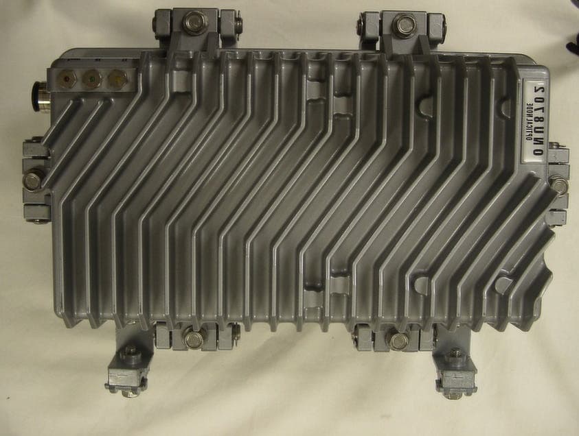
QEFONU8702
May 28, 2002Optical Mini Node
Equipment Class
JBC - Part 15 Class B Computing Device/Personal Computer