QF741054105 GPR
Geophysical Survey Systems, Inc.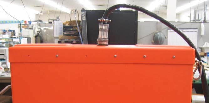
Click to zoom
Application Details
- Equipment Class
- UWB - Ultra Wideband Transmitter
- Date of Grant
- Nov 25, 2004
- Application Purpose
- Original Equipment
- Date of Application
- Oct 03, 2004
- Equipment Note
- 4105 GPR
- Frequency Range
- 540.10000000 - 936.56000000
- Country
- United States
Documents & Files
Document Text
Text extracted from the exhibit documents filed with the FCC. Open a document above to read the original.
Users Manual
Model 4105 Horn Antenna System Settings and User Notes The Difference is the Data 13 Klein Drive, P.O. Box 97 North Salem, NH 03073-0097 Phone: (603) 893-1109 / Fax: (603) 889-3984 www.Geophysical.com [email protected] September 2004 Geophysical Survey Systems, Inc. Geophysical Survey Systems, Inc. Model 4105 Antenna System Settings and User’s Notes MN 34-559 Rev C LIMITED WARRANTY, LIMITATIONS OF LIABILITY AND RESTRICTIONS Geophysical Survey Systems, Inc. hereinafter referred to as GSSI, warrants that, for a period of 24 months from the delivery date to the original purchaser, this GSSI product will be free from defects in materials and workmanship. EXCEPT FOR THE FOREGOING LIMITED WARRANTY, GSSI DISCLAIMS ALL WARRANTIES, EXPRESS OR IMPLIED, INCLUDING ANY WARRANTY OF MERCHANTABILITY OR FITNESS FOR A PARTICULAR PURPOSE. GSSI's obligation is limited to repairing or replacing parts or equipment which are returned to GSSI, transportation and insurance pre-paid, without alteration or further damage, and which in GSSI's judgment, were defective or became defective during normal use. GSSI ASSUMES NO LIABILITY FOR ANY DIRECT, INDIRECT, SPECIAL, INCIDENTAL OR CONSEQUENTIAL DAMAGES OR INJURIES CAUSED BY PROPER OR IMPROPER OPERATION OF ITS EQUIPMENT OR SOFTWARE, WHETHER OR NOT DEFECTIVE. Before returning any equipment to GSSI, a Return Material Authorization (RMA) number must be obtained. Please call the GSSI Customer Service Manager who will assign an RMA number. Be sure to have the serial number of the unit available. GSSI does not convey any license under its patent or other intellectual property rights or the rights of others. NOTE: Information in this manual is subject to change without notice. Please consult the manual updates supplied with your system and contact GSSI with any additional questions. Copyright © 2003, 2004 Geophysical Survey Systems, Inc. All rights reserved including the right of reproduction in whole or in part in any form. Published by Geophysical Survey Systems, Inc. 13 Klein Drive North Salem, New Hampshire 03073-0097 Printed in the United States GSSI and SIR are registered trademarks of Geophysical Survey Systems, Inc. Windows is a registered trademark of the Microsoft Corporation. Geophysical Survey Systems, Inc. Model 4105 Antenna System Settings and User’s Notes MN 34-559 Rev C FCC Notice (for U.S. Customers): This device complies with part 15 of the FCC Rules: Operation is subject to the following conditions: 1. This device many not cause harmful interference, and 2. This device must accept any interference received, Including interference that may cause undesired operation Warning: Changes or modifications to this unit not expressly approved by the party responsible for compliance could void the user’s authority to operate the equipment. Operation of this device is restricted to law enforcement, fire and rescue officials, scientific research institutes, commercial mining companies, and construction companies. Operation by any other party is a violation of 47 U.S.C. § 301 and could subject the operator to serious legal penalties. Coordination Requirements. (a) UWB imaging systems require coordination through the FCC before the equipment may be used. The operator shall comply with any constraints on equipment usage resulting from this coordination. (b) The users of UWB imaging devices shall supply detailed operational areas to the FCC Office of Engineering and Technology who shall coordinate this information with the Federal Government through the National Telecommunications and Information Administration. The information provided by the UWB operator shall include the name, address and other pertinent contact information of the user, the desired geographical area of operation, and the FCC ID number and other nomenclature of the UWB device. This material shall be submitted to the following address: Frequency Coordination Branch., OET Federal Communications Commission 445 12 th Street, SW Washington, D.C. 20554 ATTN: UWB Coordination (d) Users of authorized, coordinated UWB systems may transfer them to other qualified users and to different locations upon coordination of change of ownership or location to the FCC and coordination with existing authorized operations. (e) The NTIA/FCC coordination report shall include any needed constraints that apply to day-to-day operations. Such constraints could specify prohibited areas of operations or areas located near authorized radio stations for which additional coordination is required before operation of the UWB equipment. If additional local coordination is required, a local coordination contact will be provided. (f) The coordination of routine UWB operations shall not take longer than 15 business days from the receipt of the coordination request by NTIA. Special temporary operations may be handled with an expedited turn-around time when circumstances warrant. The operation of UWB systems in emergency situations involving the safety of life or property may occur without coordination provided a notification procedure, similar to that contained in CFR47 Section 2.405(a)-(e), is followed by the UWB equipment user. NOTICE: Use of this device as a wall imaging system is prohibited by FCC regulations. Geophysical Survey Systems, Inc. Model 4105 Antenna System Settings and User’s Notes MN34-559 Rev C 1 Introduction Thank you for purchasing a Model 4105 High Frequency Air Launched Antenna (Horn). The 4105 Horn represents the state of the art in high-speed, high-resolution pavement thickness and bridge deck analysis ground penetrating equipment. This antenna is designed for applications requiring very high resolution survey from a moving vehicle. The unique air-launched design allows you to survey at high speeds without causing damage and wear to the antenna. Furthermore, it allows GSSI’s RADAN post-processing software to separate the direct-coupling reflection from the pavement surface reflection. This allows a very accurate mea…
Text truncated - open the document above for the full version.
Attestation Statements
_________________________________________________________________________________________________________________ Geophysical Survey Systems, Inc. _________________________________________________________________________________________________________________ 13 Klein Drive - P.O. Box 97, North Salem, NH 03073-0097, U.S.A. / Telephone (603) 893-1109 Fax (603) 889-3984 website www.geophysical.com e-mail [email protected] September 17, 2004 Attention: Application Examiner Reviewing Engineer Re: Attestation Statement Applicant: Geophysical Survey Systems, Inc. FRN: 0007-2729-25 FCC ID: QF74105 To whom it may concern, The internal photographs submitted with this application are the same as was EMI tested. Sincerely, Dennis J. Johnson President, Geophysical Survey Systems, Inc.
Cover Letter(s)
_________________________________________________________________________________________________________________ Geophysical Survey Systems, Inc. _________________________________________________________________________________________________________________ 13 Klein Drive - P.O. Box 97, North Salem, NH 03073-0097, U.S.A. / Telephone (603) 893-1109 Fax (603) 889-3984 website www.geophysical.com e-mail [email protected] September 17, 2004 Attention: Application Examiner Reviewing Engineer Re: Request for confidentiality Applicant: Geophysical Survey Systems, Inc. FRN: 0007-2729-25 FCC ID: QF74105 To whom it may concern, Request is hereby submitted by Geophysical Survey Systems, Inc., to withhold from public review certain portions of the application for equipment certification for the referenced FCC identifier. In particular, the following sections of the application are requested to be kept confidential: • Schematics • Detailed Block diagrams • Detailed Operational/Functional Description Rationale for request for confidentiality: Geophysical Survey Systems, Inc. has invested considerable time and materials in research and development to produce the referenced product. Disclosure of the confidential portions of this application to competitors would not only give them significant competitive advantages in developing similar products, but would also disclose successful implementation of unpublished, leading edge technology developed by us. The fee for confidentiality has been submitted along with the fee for certification. If you have questions or need further information, please contact the undersigned. Sincerely, Dennis J. Johnson President, Geophysical Survey Systems, Inc.
External Photos
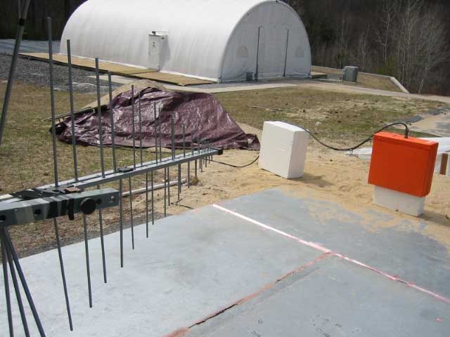
QF74105 ANTENNA EXTERNAL PHOTOS Page 1 of 2 Front View Side View QF74105 ANTENNA EXTERNAL PHOTOS Page 2 of 2 Top View
ID Label/Location Info
QF74105 LABEL LOCATION LABELS TO READ: LABEL MATERIAL: THESE LABELS ARE PERMANENT FOR THE LIFE OF THE PRODUCT. THEY ARE REVERSE SCREEN-PRINTED ON 8 MIL POLYESTER FILM WITH PERMANENT ADHESIVE. THIS DEVICE COMPLIES WITH PART 15 OF THE FCC RULES. OPERATION IS SUBJECT TO THE FOLLOWING 2 CONDITIONS: 1. THIS DEVICE MAY NOT CAUSE HARMFUL INTERFERENCE. 2. THIS DEVICE MUST ACCEPT ANY INTERFERENCE RECEIVED, INCLUDING INTERFERENCE THAT MAY CAUSE UNDESIRED OPERATION. MADE IN USA FCC ID. QF74105 1.25 " 3.5" FCC LABELS Operation of this device is restricted to law enforcement, fire and rescue officials, scientific research institutes, commercial mining companies, and construction companies. Operation by any other party is a violation of 47 U.S.C. § 301 and could subject the operator to serious legal penalties.
Internal Photos
QF74105 ANTENNA INTERNAL PHOTOS REMOVED FROM CASE FAN PCB PARTLY VISIBLE Page 1 of 8 QF74105 ANTENNA INTERNAL PHOTOS PC BOARDS SHOWN ABOVE: 1. ELECTRONICS INTERFACE BOARD (MAIN BOARD ON BOTTOM) 2. DELAY LINE PCB (CENTER) 3. MONOCYCLE GENERATOR (MOUNTED ON LEFT SIDE) 4. RF AMPLIFIER (MOUNTED ON RIGHT SIDE) 5. RECEIVER SAMPLER (SECOND MODULE MOUNTED FROM RIGHT) Page 2 of 8 QF74105 ANTENNA INTERNAL PHOTOS 1. ELECTRONICS INTERFACE BOARD Back Top Page 3 of 8 QF74105 ANTENNA INTERNAL PHOTOS 2. DELAY LINE PC BOARD TOP BACK Page 4 of 8 QF74105 ANTENNA INTERNAL PHOTOS 3. MONOCYCLE GENERATOR Back Top 4. RF AMPLIFIER Page 5 of 8 QF74105 ANTENNA INTERNAL PHOTOS TOP 5. RECEIVER SAMPLER TOP Page 6 of 8 QF74105 ANTENNA INTERNAL PHOTOS BOTTOM 6. FAN PC BOARD Page 7 of 8 QF74105 ANTENNA INTERNAL PHOTOS 7. BACK SIDE OF FAN BOARD Page 8 of 8
Test Report
AA FCC Subpart 15FPage 2 of 27 Project Number: 3063582Report number: 3063582_4105_Emission EXECUTIVE SUMMARY.....................................................................................................................................................................................................................................4 1.INTRODUCTION.............................................................................................................................................................................................................................................5 1.1.CLIENT INFORMATION............................................................................................................................................5 1.2.TEST PLAN REFERENCE..........................................................................................................................................5 1.3.EQUIPMENT UNDER TEST (EUT)...........................................................................................................................5 1.3.1System Support Equipment..........................................................................................................................5 1.3.2System Block Diagram..................................................................................................................................5 1.3.3Justification....................................................................................................................................................5 1.3.4Mode(s) of Operation....................................................................................................................................5 1.4.MODIFICATIONS REQUIRED FOR COMPLIANCE......................................................................................................5 2.TEST ENVIRONMENT..............................................................................................................................................................................................................................7 2.1.TEST FACILITY........................................................................................................................................................7 2.2.TEST EQUIPMENT....................................................................................................................................................7 2.3.SAMPLE CALCULATIONS.........................................................................................................................................7 2.3.1Field Strength Calculation............................................................................................................................7 2.3.2EIRP Calculation...........................................................................................................................................7 2.3.3Spectrum Analyzer Setup.............................................................................................................................8 2.4.MEASUREMENT UNCERTAINTY.............................................................................................................................9 3.ULTRA WIDEBAND OPERATION...............................................................................................................................................................................................10 3.1.OPERATIONAL LIMITATIONS (SECTION 15.521)..................................................................................................10 3.2.UWB BANDWIDTH (SECTION 15.503(A))............................................................................................................10 3.2.1Requirement (low-frequency imaging systems).......................................................................................10 3.2.2Test Procedure.............................................................................................................................................10 3.2.3Test Results..................................................................................................................................................10 3.3.PEAK EMISSIONS 50MHZ RESOLUTION BANDWIDTH (SECTION 15.509(F)).....................................................11 3.3.1Limit..............................................................................................................................................................11 3.2.2Test Procedure.............................................................................................................................................11 3.3.3Test Results..................................................................................................................................................11 4.RADIATED EMISSIONS.........................................................................................................................................................................................................................12 4.1.SECTION 5.209(D) QUASI-PEAK...........................................................................................................................12 4.1.1Limit..............................................................................................................................................................12 4.1.2Test Procedure.............................................................................................................................................12 4.1.3Test Results..................................................................................................................................................13 4.2.SECTION 15.509(D) RMS >960MHZ..................................................................................................................14 4.2.1Limit...................................................................................................................…
Text truncated - open the document above for the full version.
Contact Information
Applicant
Jay Desruisseaux(Quality Manager)
Technical Contact
Geophysical Survey Systems, Inc .Alan Schutz
[email protected]603 893 1109
13 Klein Drive · North Salem, New Hampshire · United States
Non-Technical Contact
Geophysical Survey Systems, Inc.Alan Schutz
[email protected]603 893 1109
Test Firm
Intertek Testing Services NA Inc.Roland Gubisch
Technical Specifications
| # | Rule Parts | Frequency Range | Power Output |
|---|---|---|---|
| 1 | 15F | 540.1 MHz - 936.56 MHz | - |
Other Applications from Geophysical Survey Systems, Inc.
QF7NX0410
Apr 22, 2026GPR Compass NX NX04/10
Equipment Class
UWB - Ultra Wideband Transmitter
QF7NX25
Aug 30, 2023GPR NX25
Equipment Class
UWB - Ultra Wideband Transmitter
QF7D50300800
Dec 10, 2012Ground Penetrating Radar Antenna
Equipment Class
UWB - Ultra Wideband Transmitter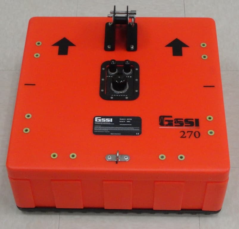
QF750270S
Oct 25, 2012Ground Penetrating Radar Antenna
Equipment Class
UWB - Ultra Wideband Transmitter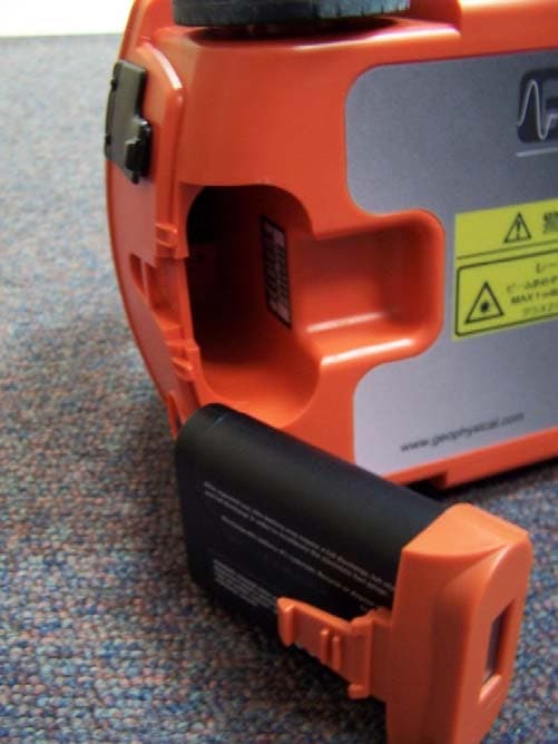
QF7MINIHR
Dec 27, 2011Ground penetrating radar
Equipment Class
UWB - Ultra Wideband Transmitter