QF75040050400 Antenna
Geophysical Survey Systems, Inc.Application Details
- Equipment Class
- UWB - Ultra Wideband Transmitter
- Date of Grant
- Feb 23, 2009
- Application Purpose
- Original Equipment
- Date of Application
- Oct 02, 2008
- Equipment Note
- 50400 Antenna
- Frequency Range
- 35.45000000 - 213.10000000
- Country
- United States
Documents & Files
Document Text
Text extracted from the exhibit documents filed with the FCC. Open a document above to read the original.
Cover Letter(s)
12 Industrial Way Tel 603.893.1109 • Fax 603-889-3984 Salem, NH 03079 www.geophysical.com • [email protected] Geophysical Survey Systems, Inc. Letter of Agency I appoint Intertek Testing Services NA Inc. to act on our behalf in front of the Federal Communications Commission with respect to all matters relating to certification of equipment under the FCC rules until further notice. I further certify that no party (as defined in 1.2002 of CFR 47, 1995) to this application, including myself, is subject to denial of federal benefits, that includes FCC benefits, pursuant to Section 5301 of the Anti-Drug Abuse Act of 1988, 21 U.S.C.,853A. Equipment: ________QF750400 _____________________________________________________________ ______________________________________________________________________________ _____________________________________________________________________ Dated this __21 ___day of____July _________, 2008___. _____________________________________ Signature Alan E. Schutz _____________________________________ Name Vice President of Technology _____________________________________ Title Geophysical Survey Systems, Inc. _____________________________________ Company 603-893-1109 _____________________________________ Telephone
Cover Letter(s)
12 Industrial Way Tel 603.893.1109 • Fax 603-889-3984 Salem, NH 03079 www.geophysical.com • [email protected] Geophysical Survey Systems, Inc. July 21, 2008 Attention: Application Examiner Reviewing Engineer Re: Request for confidentiality Applicant: Geophysical Survey Systems, Inc. FRN: 0007-2729-25 FCC ID: QF750400 To whom it may concern, Request is hereby submitted by Geophysical Survey Systems, Inc., to withhold from public review certain portions of the application for equipment certification for the referenced FCC identifier. In particular, the following sections of the application are requested to be kept confidential: • Schematics • Detailed Block diagrams • Detailed Operational/Functional Description Rationale for request for confidentiality: Geophysical Survey Systems, Inc. has invested considerable time and materials in research and development to produce the referenced product. Disclosure of the confidential portions of this application to competitors would not only give them significant competitive advantages in developing similar products, but would also disclose successful implementation of unpublished, leading edge technology developed by us. A separate letter justifying confidential treatment of the internal photographs is included. The fee for confidentiality has been submitted along with the fee for certification. If you have questions or need further information, please contact the undersigned. Sincerely, Alan E. Schutz Vice President of Technology Geophysical Survey Systems, Inc. Geophysical Survey Systems, Inc. 12 Industrial Way Tel 603.893.1109 • Fax 603-889-3984 Salem, NH 03079 www.geophysical.com • [email protected]
Test Report
Report Number: 3153005BOX-001d Page 1 of 17 EMISSION TEST REPORT Report Number: 3153005BOX-001d Project Number: 3153005 Testing performed on the Ground Penetration Radar Model: 50400 To FCC Part 15 Subpart F – Ultra-Wideband Operation For Geophysical Survey Systems, Inc. Test Performed by: Test Authorized by: Intertek – ETL SEMKO 70 Codman Hill Road Boxborough, MA 01719 Geophysical Survey Systems, Inc. 12 Industrial Way Salem, NH 03079 Prepared by: Date: 10/03/08 Kouma Sinn, Sr. Project Engineer Reviewed by: Date: 10/03/08 Jeff Goulet, Engineering Team Leader, EMC This report is for the exclusive use of Intertek’s Client and is provided pursuant to the agreement between Intertek and its Client. Intertek’s responsibility and liability are limited to the terms and conditions of the agreement. Intertek assumes no liability to any party, other than to the Client in accordance with the agreement, for any loss, expense or damage occasioned by the use of this report. Only the Client is authorized to copy or distribute this report and then only in its entirety. Any use of the Intertek name or one of its marks for the sale or advertisement of the tested material, product or service must first be approved in writing by Intertek. The observations and test results in this report are relevant only to the sample tested. This report by itself does not imply that the material, product, or service is or has ever been under an Intertek certification program. This report must not be used to claim product endorsement by A2LA, NIST nor any other agency of the U.S. Government. Report Number: 3153005BOX-001d Page 2 of 17 1.0 Job Description 1.1 Client Information: This equipment under test (EUT) has been tested at the request of: Company: Geophysical Survey Systems, Inc. 12 Industrial Way Salem, NH 03079 Contact: Alan Schutz Telephone: (603) 893-1109 Fax: (603) 889-3984 Email: [email protected] 1.2 Equipment Under Test: Equipment Type: Ground Penetration Radar Model Number(s): 50400 Serial number(s): 001 Manufacturer: Geophysical Survey Systems, Inc. EUT receive date: May 22, 2008 EUT received condition: Production unit was received with no visible damage Test start date: May 22, 2008 Test end date: May 22, 2008 1.3 Test Plan Reference: ANSI C63.4-2003 1.4 Test Configuration: 1.4.1 EUT Voltage Range: The EUT powers from Survey Controller, Model SIR20. 1.4.2 Cables: Description Shielding Connector Length (m) Qty. AC Mains None Plastic 2 1 AC Adapter None Plastic 2 1 Control Braid Metal 5 1 Report Number: 3153005BOX-001d Page 3 of 17 1.4.3 Support Equipment: Description Manufacturer Model Serial No. Survey Controller GSSI SIR-20 MF-20/1000 001 Power Supply GSSI 08/4 350 1.4.4 Block Diagram: 1.5 Mode(s) of Operation: The EUT was continuous transmitting and collecting data during testing. 1.6 Modifications Required For Compliance: None Report Number: 3153005BOX-001d Page 4 of 17 2.0 Test Summary: TEST STANDARD RESULTS FCC Part 15 Subpart F – Ultra-Wideband Operation SUB-TEST TEST PARAMETER PASS/FAIL Radiated Emissions Per Standard Specifications Pass 10 dB Bandwidth The UWB bandwidth is the frequency band bounded by the points that are 10 dB below the highest radiated emission, as based on the complete transmission system including the antenna. The fractional bandwidth shall be equal to or greater than 0.20 or has a UWB bandwidth equal to or greater than 500 MHz, regardless of the fractional bandwidth. Pass Line Conducted Emissions Not Applicable -- REVISION SUMMARY – The following changes have been made to this Report: Date Project No. Project Handler Page(s) Item Description of Change 5/30/08 3153005 Kouma Sinn 12, 13, 16, 17, 20, 21 Radiated Emissions Data Changed data from 960MHz-10GHz from AVG to RMS 7/14/08 3153005 Kouma Sinn Whole report Model # change Changed model # from 4105A to 42000 7/14/08 3153005 28 10 dB BW for Model 4105A Changed the statement “The UWB Bandwidth >500MHz” to “The UWB Bandwidth is greater than 500MHz, therefore, fractional bandwidth calculation is not necessary” 10/02/08 3153005 Kouma Sinn Whole Report Separated report for each model # The original report has three models in it. Need to separate report for each model for FCC certification. Report Number: 3153005BOX-001d Page 5 of 17 3.0 Sample Calculations: The field strength is calculated by adding the Antenna Factor and Cable Factor, and subtracting the Amplifier Gain (if any) from the measured reading. The basic equation with a sample calculation is as follows: FS = RA + AF + CF - AG Where FS = Field Strength in dBμV/m RA = Receiver Amplitude (including preamplifier) in dBμV CF = Cable Attenuation Factor in dB AF = Antenna Factor in dB AG = Amplifier Gain in dB In the following table(s), the reading shown on the data table reflects the preamplifier gain. An example for the calculations in the following table is as follows. Assume a receiver reading of 52.0 dBμV is obtained. The antenna factor of 7.4 dB and cable factor of 1.6 dB is added. The amplifier gain of 29 dB is subtracted, giving a field strength of 32 dBμV/m. This value in dBμV/m was converted to its corresponding level in μV/m. RA = 52.0 dBμV AF = 7.4 dB/m CF = 1.6 dB AG = 29.0 dB FS = 32 dBμV/m Level in μV/m = [10( 32 dBμV/m)/20] = 39.8 μV/m The following is how net line-conducted readings were determined: NF = RF + LF + CF + AF Where NF = Net Reading in dBμV RF = Reading from receiver in dBμV LF = LISN Correction Factor in dB CF = Cable Correction Factor in dB AF = Attenuator Loss Factor in dB To convert from dBμV to μV or mV the following was used: UF = 10 (NF / 20) where UF = Net Reading in μV Example: NF = RF + LF + CF + AF = 28.5 + 0.2 + 0.4 + 20.0 = 49.1 dBμV UF = 10 (48.1 dBμV / 20) = 254 μV/m Report Number: 3153005BOX-001d Page 6 of 17 4.0 Measurement Uncertainty: Compliance of the product is based on the measured value. However, the measurement uncertainty is included for informational purposes. The expanded uncertainty (k = 2) for radiated emissions from …
Text truncated - open the document above for the full version.
Test Setup Photos
Test Setup Photo
Contact Information
Applicant
Jay Desruisseaux(Quality Manager)
Technical Contact
Geophysical Survey Systems, Inc.Alan Schutz
[email protected]603-893-1109
12 Industrial Way · Salem, New Hampshire · United States
Non-Technical Contact
Geophysical Survey Systems, Inc.Alan Schutz
[email protected]603-893-1109
Test Firm
Intertek Testing Services NA Inc.Yaqing Liu
[email protected]978 635 8662
Technical Specifications
| # | Rule Parts | Frequency Range | Power Output |
|---|---|---|---|
| 1 | 15F | 35.45 MHz - 213.1 MHz | - |
Other Applications from Geophysical Survey Systems, Inc.
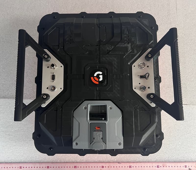
QF7NX0410
Apr 22, 2026GPR Compass NX NX04/10
Equipment Class
UWB - Ultra Wideband Transmitter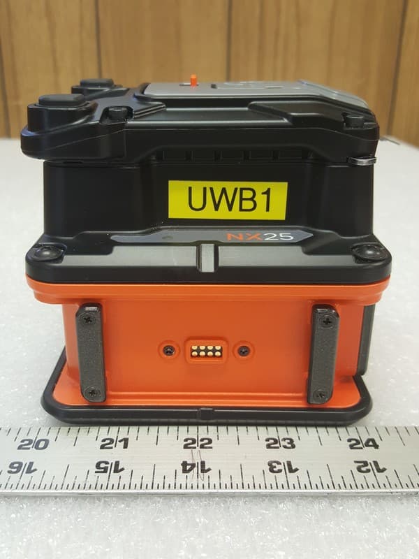
QF7NX25
Aug 30, 2023GPR NX25
Equipment Class
UWB - Ultra Wideband Transmitter
QF7D50300800
Dec 10, 2012Ground Penetrating Radar Antenna
Equipment Class
UWB - Ultra Wideband Transmitter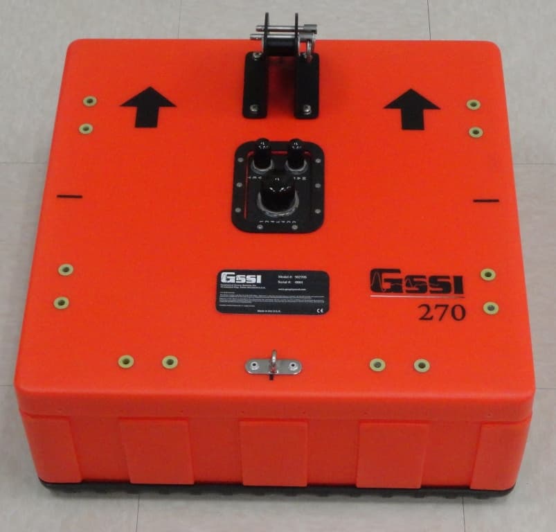
QF750270S
Oct 25, 2012Ground Penetrating Radar Antenna
Equipment Class
UWB - Ultra Wideband Transmitter
QF7MINIHR
Dec 27, 2011Ground penetrating radar
Equipment Class
UWB - Ultra Wideband Transmitter