QF751065106 Antenna
Geophysical Survey Systems, Inc.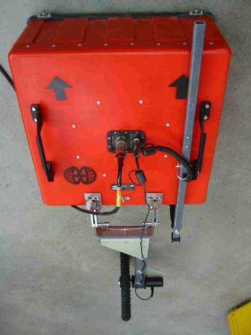
Click to zoom
Application Details
- Equipment Class
- UWB - Ultra Wideband Transmitter
- Date of Grant
- Sep 11, 2002
- Application Purpose
- Original Equipment
- Date of Application
- Jul 10, 2002
- Equipment Note
- 5106 Antenna
- Frequency Range
- 60.00000000 - 270.00000000
- Country
- United States
Documents & Files
Document Text
Text extracted from the exhibit documents filed with the FCC. Open a document above to read the original.
Users Manual
Geophysical Survey Systems, Inc. Model 5106 Antenna System Settings and User Notes Manual MN30-191 Rev - 1 Model 5106 Antenna System Settings and User Notes We Provide Complete Survey Solutions Geophysical Survey Systems, Inc. 13 Klein Drive, P.O. Box 97 North Salem, NH 03073-0097 Phone: (603) 893-1109 / FAX: (603) 889-3984 www.geophysical.com [email protected] Manual MN30-191 Rev - 2 Limited Warranty, Limitations Of Liability And Restrictions Geophysical Survey Systems, Inc. hereinafter referred to as GSSI, warrants that, for a period of 12 months from the delivery date to the original purchaser, GSSI's products will be free from defects in materials and workmanship. EXCEPT FOR THE FOREGOING LIMITED WARRANTY, GSSI DISCLAIMS ALL WARRANTIES, EXPRESS OR IMPLIED, INCLUDING ANY WARRANTY OF MERCHANTABILITY OR FITNESS FOR A PARTICULAR PURPOSE. GSSI's obligation is limited to repairing or replacing parts or equipment which are returned to GSSI, transportation and insurance pre-paid, without alteration or further damage, and which in GSSI's judgment, were defective or became defective during normal use. GSSI ASSUMES NO LIABILITY FOR ANY DIRECT, INDIRECT, SPECIAL, INCIDENTAL OR CONSEQUENTIAL DAMAGES OR INJURIES CAUSED BY PROPER OR IMPROPER OPERATION OF ITS EQUIPMENT OR SOFTWARE, WHETHER OR NOT DEFECTIVE. Before returning any equipment to GSSI, a Return Material Authorization (RMA) number must be obtained. Please call the GSSI Customer Service Manager who will assign an RMA number. Be sure to have the serial number of the unit available. GSSI does not convey any license under its patent or other intellectual property rights or the rights of others. Note: Information in this manual is subject to change without notice. Please consult the manual updates supplied with your system and contact GSSI with any additional questions. Copyright© 2001, 2002 Geophysical Survey Systems, Inc. All rights reserved, including the right of reproduction in whole or in part in any form Published by Geophysical Survey Systems, Inc. 13 Klein Drive North Salem, New Hampshire 03073-0097 Printed in the United States GSSI and SIR are registered trademarks of Geophysical Survey Systems, Inc. Manual MN30-191 Rev - 2 GSSI is required to notify customers of the following restrictions. However, GSSI and other GPR manufacturers have challenged these regulations. This device complies with part 15 of the FCC Rules: Operation is subject to the following conditions: 1. This device many not cause harmful interference, and 2. This device must accept any interference received, Including interference that may cause undesired operation Warning: Changes or modifications to this unit not expressly approved by the party responsible for compliance could void the user’s authority to operate the equipment. Operation of this device is restricted to law enforcement, fire and rescue officials, scientific research institutes, commercial mining companies, and construction companies. Operation by any other party is a violation of 47 U.S.C. § 301 and could subject the operator to serious legal penalties. Coordination Requirements. (a) UWB imaging systems require coordination through the FCC before the equipment may be used. The operator shall comply with any constraints on equipment usage resulting from this coordination. (b) The users of UWB imaging devices shall supply detailed operational areas to the FCC Office of Engineering and Technology who shall coordinate this information with the Federal Government through the National Telecommunications and Information Administration. The information provided by the UWB operator shall include the name, address and other pertinent contact information of the user, the desired geographical area of operation, and the FCC ID number and other nomenclature of the UWB device. This material shall be submitted to the following address: Frequency Coordination Branch., OET Federal Communications Commission 445 12 th Street, SW Washington, D.C. 20554 ATTN: UWB Coordination (d) Users of authorized, coordinated UWB systems may transfer them to other qualified users and to different locations upon coordination of change of ownership or location to the FCC and coordination with existing authorized operations. (e) The NTIA/FCC coordination report shall include any needed constraints that apply to day-to-day operations. Such constraints could specify prohibited areas of operations or areas located near authorized radio stations for which additional coordination is required before operation of the UWB equipment. If additional local coordination is required, a local coordination contact will be provided. (f) The coordination of routine UWB operations shall not take longer than 15 business days from the receipt of the coordination request by NTIA. Special temporary operations may be handled with an expedited turn-around time when circumstances warrant. The operation of UWB systems in emergency situations involving the safety of life or property may occur without coordination provided a notification procedure, similar to that contained in CFR47 Section 2.405(a)-(e), is followed by the UWB equipment user. Manual MN30-191 Rev - 2 Model 5106 Antenna The Model 5106 antenna has greatly improved resolution performance over previous GSSI mid- frequency antennas, such as the Model 3105 (300 MHz). The Model 5106 can be used in continuous, survey wheel or static stacking modes. The Model 5106 can only be used with a “deadman” switch with the SIR-20 or SIR-3000 control units.. These systems are designed to drive the antenna at its maximum rated pulse repetition frequency of 100 KHz. System Setup - Standard Settings Shallow Profiling: Range/Depth is approximately 7m assuming a dielectric constant of 9. Setup Mode: Manual System Run Mode: Survey Wheel (recommended) or Continuous Range:150 ns Number of Gain Points: 5 Vertical Low Pass Filter: 400 MHz Vertical High Pass Filter: 30 MHz Samples per Scan: 512 Bits per Sample: 16 Scans per Seco…
Text truncated - open the document above for the full version.
Users Manual
Geophysical Survey Systems, Inc. Model 5106 Antenna System Settings and User Notes Manual MN30-191 Rev A FCC NOTICES: This device complies with part 15 of the FCC Rules: Operation is subject to the following conditions: 1. This device many not cause harmful interference, and 2. This device must accept any interference received, Including interference that may cause undesired operation Warning: Changes or modifications to this unit not expressly approved by the party responsible for compliance could void the user’s authority to operate the equipment. Operation of this device is restricted to law enforcement, fire and rescue officials, scientific research institutes, commercial mining companies, and construction companies. Operation by any other party is a violation of 47 U.S.C. § 301 and could subject the operator to serious legal penalties. Coordination Requirements. (a) UWB imaging systems require coordination through the FCC before the equipment may be used. The operator shall comply with any constraints on equipment usage resulting from this coordination. (b) The users of UWB imaging devices shall supply detailed operational areas to the FCC Office of Engineering and Technology who shall coordinate this information with the Federal Government through the National Telecommunications and Information Administration. The information provided by the UWB operator shall include the name, address and other pertinent contact information of the user, the desired geographical area of operation, and the FCC ID number and other nomenclature of the UWB device. This material shall be submitted to the following address: Frequency Coordination Branch., OET Federal Communications Commission 445 12 th Street, SW Washington, D.C. 20554 ATTN: UWB Coordination (d) Users of authorized, coordinated UWB systems may transfer them to other qualified users and to different locations upon coordination of change of ownership or location to the FCC and coordination with existing authorized operations. (e) The NTIA/FCC coordination report shall include any needed constraints that apply to day-to-day operations. Such constraints could specify prohibited areas of operations or areas located near authorized radio stations for which additional coordination is required before operation of the UWB equipment. If additional local coordination is required, a local coordination contact will be provided. (f) The coordination of routine UWB operations shall not take longer than 15 business days from the receipt of the coordination request by NTIA. Special temporary operations may be handled with an expedited turn-around time when circumstances warrant. The operation of UWB systems in emergency situations involving the safety of life or property may occur without coordination provided a notification procedure, similar to that contained in CFR47 Section 2.405(a)-(e), is followed by the UWB equipment user. NOTICE: Use of this device as a wall imaging system is prohibited by FCC regulations.
Cover Letter(s)
_____________________________________________________________________________________________________________ Geophysical Survey Systems, Inc. _____________________________________________________________________________________________________________ 13 Klein Drive - P.O. Box 97, North Salem, NH 03073-0097, U.S.A. / Telephone (603) 893-1109 Fax (603) 889-3984 website www.geophysical.com e-mail [email protected] July 2, 2002 Attention: Application Examiner Reviewing Engineer Re: Request for confidentiality Applicant: Geophysical Survey Systems, Inc. FRN: 0007-2729-25 FCC ID: QF7-5100, QF7-5106 and QF7-INTERRAGATOR To whom it may concern, Request is hereby submitted by Geophysical Survey Systems, Inc., to withhold from public review certain portions of the application for equipment certification for the referenced FCC identifiers. In particular, the following sections of the application are requested to be kept confidential: • Schematics • Detailed Block diagrams • Detailed Operational/Functional Description Rationale for request for confidentiality: Geophysical Survey Systems, Inc. has invested considerable time and materials in research and development to produce the referenced product. Disclosure of the confidential portions of this application to competitors would not only give them significant competitive advantages in developing similar products, but would also disclose successful implementation of unpublished, leading edge technology developed by us. The fee for confidentiality has been submitted along with the fee for certification. If you have questions or need further information, please contact the undersigned. Sincerely, Dennis J. Johnson President, Geophysical Survey Systems, Inc.
Cover Letter(s)
Letter of Agency I appoint Intertek Testing Services NA Inc. to act on our behalf in front of the Federal Communications Commission with respect to all matters relating to certification of equipment under the FCC rules until further notice. I further certify that no party (as defined in 1.2002 of CFR 47, 1995) to this application, including myself, is subject to denial of federal benefits, that includes FCC benefits, pursuant to Section 5301 of the Anti-Drug Abuse Act of 1988, 21 U.S.C.,853A. Equipment: __QF7-5100, QF7-5106 AND QF7-INTERRAGATOR ________________________________________________________________________ ________________________________________________________________________ Dated this __1st_day of_July, 2002___. _____________________________________ Signature Dennis J. Johnson______________________ Name President______________________________ Title Geophysical Survey Systems, Inc._________ Company 603-893-1109_________________________ Telephone
Cover Letter(s)
_____________________________________________________________________________________________________________ Geophysical Survey Systems, Inc. _____________________________________________________________________________________________________________ 13 Klein Drive - P.O. Box 97, North Salem, NH 03073-0097, U.S.A. / Telephone (603) 893-1109 Fax (603) 889-3984 website www.geophysical.com e-mail [email protected] July 2, 2002 Attention: Application Examiner Reviewing Engineer Re: Attestation Statement Applicant: Geophysical Survey Systems, Inc. FRN: 0007-2729-25 FCC ID: QF7-5106 To whom it may concern, The internal photographs submitted with this application are the same as was EMI tested. Sincerely, Dennis J. Johnson President, Geophysical Survey Systems, Inc.
Cover Letter(s)
To the Reviewer: I incorrectly specified the frequency range of operation on the Form 731. It should read “0.1 – 900 MHz” as the frequency range of operation of the EUT. I was deriving my information from an incorrect source. Please amend the certification to reflect this. Tha nk yo u, Nicholas Abbondante Engi neer ITS ETL-SEMKO Boxborough Phone: 978-635-8542 Fax: 978-263-2662
Cover Letter(s)
To: Alan Schutz, Geophysical Survey Systems Inc From: Andy Leimer [email protected] FCC Application Processing Branch Re: FCC ID QF75106 Applicant: Geophysical Survey Systems, Inc. Correspondence Reference Number: 23481 731 Confirmation Number: EA740530 1) More information is needed on the 0.5 ns pulse. Is the pulse pseudo random (dithered) or is it periodic (You mentioned a maximum PRF of 100 kHz). Upload a plot of the pulse. The pulse is not dithered, it is a fixed frequency. 100 KHz is the maximum allowable PRF because that is the frequency at which the emissions test was performed. The picture below shows the shape of the pulse. (The horizontal scale is in ns.) 2) Measurements from 960 MHz to 1 GHz were done using a horn antenna. Remeasure this band using a bicon antenna. The horn antenna is calibrated down to 900MHz so the bicon should not be necessary. There are no emissions above 960 that are not related to the UWB transmission so no quasi-peak data is presented. To cover the entire range from 30 MHz to 10 GHz, two different setups were used, including changing the analyzer, antenna, cables, preamp and procedure. If we can’t use the horn between 960 and 1000, then a third setup is required. 3) It appears that there is no shielding above the antenna. What measures have been taken to ensure that the emissions from the top of the device are less than the ground penetrating emissions. The antenna is entirely within a shielded metal box. Only the bottom is open (where the fans are). 4) There is a procedure in the test report for the -10 dB points but no data or plots. Upload a spectrum plot and data for the -10 dB points. I suggest a field strength measurement for these points to account for non-linearities across the band that would be on the spectrum plot (ie: antenna and amplifier is not equal across the band). From the plot below, the peak is at 224 MHz. The lower –10 dB point is 112 MHz. The upper –10 dB point is 316 MHz. All data has already been corrected for antenna, amplifier, cables, etc. The data tables are in the test report. 5) What type of imaging system is this (low, mid, or high frequency). What is the center frequency? This is a low frequency system. The center frequency is 214 MHz. 6) Heading missing on some test data tables. Upload corrected tables with the proper headings as shown in Table 1 of the Test Data. 7) The formula used for determining RMS level of the emission is not clear. Show how this was derived. Upload all data used for this calculation and provide a sample calculation. The items indicated above must be submitted before processing can continue on the above referenced application. Failure to provide the requested information within 60 days of the original e-mail date may result in application dismissal pursuant to Section 2.917 (c) and forfeiture of the filing fee pursuant to section 1.1108. DO NOT reply to this e-mail by using the Reply button. In order for your response to be processed expeditiously, you must upload your response via the Internet at www.fcc.gov, Electronic Filing, OET Equipment Authorization Electronic Filing. If the response is submitted through Add Attachments, in order to expedite processing, a message which informs the processing staff that a new exhibit has been submitted must also be submitted via Submit Correspondence. Also, please note that partial responses increase processing time and should not be submitted. Any questions about the content of this correspondence should be directed to the e-mail address listed below the name of the sender.
Cover Letter(s)
_____________________________________________________________________________________________________________ Geophysical Survey Systems, Inc. _____________________________________________________________________________________________________________ 13 Klein Drive - P.O. Box 97, North Salem, NH 03073-0097, U.S.A. / Telephone (603) 893-1109 Fax (603) 889-3984 website www.geophysical.com e-mail [email protected] August 15, 2002 To: Andy Leimer FCC Application Processing Branch From: Alan Schutz, Geophysical Survey Systems Inc Re: FCC ID QF75106 Applicant: Geophysical Survey Systems, Inc. Correspondence Reference Number: 23663 731 Confirmation Number: EA740530 5) Your response indicated that there is shielding above the antenna. How much shielding is provided and how effective is it in ensuring that the energy from the GPR is directed down into the ground as required in Part 15.503(f). It is recommended that you submit a field measurement from the top of the device showing compliance with the limit. This can be done by suspending an antenna above the device or by turning it on it's side and doing a table top test. 5) The shielding is a five-sided aluminum box. The emissions test had the receiving horn vary from 1 meter to 4 meters above the DUT. This has demonstrated that the shielding is sufficient to keep the air emissions below the spec curve. Photos of the top and bottom of the shield are shown below.
Cover Letter(s)
M Intertek Testing Services NA, Inc. 70 Codman Hill Road, Boxborough, MA 01719 Telephone 978-263-2662 Fax 978-263-7086 Home Page www.etlsemko.com Re: Correspondence Reference Number: 23861 FCC ID QF75106 Confirmation EA740530 This will attest to the fact that all RMS measurements above 960MHz on FCC ID QF75106 (EA740530) was performed using a Resolution Bandwidth of 1MHz and a Video Bandwidth of 3MHz. Respectfully; Robert F. Martin, N.C.E, P.E. Sr. Technical Manager Intertek Testing Services NA, Inc.
External Photos
5106 ANTENNA EXTERNAL PHOTOS Page 1 of 4 ANTENNA WITH ATTACHMENTS 5106 ANTENNA EXTERNAL PHOTOS Page 2 of 4 SIDE VIEW FRONT VIEW 5106 ANTENNA EXTERNAL PHOTOS Page 3 of 4 TOP VIEW BOTTOM VIEW SHOWING SKID PLATE 5106 ANTENNA EXTERNAL PHOTOS Page 4 of 4 DEADMAN SWITCH APPLICATION METHOD TO BE DETERMINED FCC LABEL FACSIMILE TO BE ATTACHED TO TOP OF ANTENNA NEAR CONNECTIONS. This device complies with part 15 of the FCC Rules: Operation is subject to the following conditions: a. This device many not cause harmful interference, and b. This device must accept any interference received, Including interference that may cause undesired operation Warning: Changes or modifications to this unit not expressly approved by the party responsible for compliance could void the user’s authority to operate the equipment. Operation of this device is restricted to law enforcement, fire and rescue officials, scientific research institutes, commercial mining companies, and construction companies. Operation by any other party is a violation of 47 U.S.C. § 301 and could subject the operator to serious legal penalties.
ID Label/Location Info
5106 FCC LABEL LOCATION LABEL TO READ: LABEL MATERIAL: THESE LABELS ARE PERMANENT FOR THE LIFE OF THE PRODUCT. THEY ARE REVERSE SCREEN-PRINTED ON 8 MIL POLYESTER FILM WITH PERMANENT ADHESIVE. THIS DEVICE COMPLIES WITH PART 15 OF THE FCC RULES OPERATION IS SUBJECT TO THE FOLLOWING 2 CONDITIONS: 1. THIS DEVICE MAY NOT CAUSE HARMFUL INTERFERENCE. 2. THIS DEVICE MUST ACCEPT ANY INTERFERENCE RECEIVED INCLUDING INTERFERENCE THAT MAY CAUSE UNDESIRED OPERATION. MADE IN USA FCC ID. QF75106 1.25 " 3.5" FCC LABEL
Internal Photos
5106 INTERNAL PHOTOS Page 1 of 6 5106 ANTENNA INTERNAL PHOTOS.doc.DOC 5106 ANTENNA ASSEMBLY WITH COVER REMOVED AND BOARDS PULLED OUT. BOARDS ARE, FROM LEFT TO RIGHT, DIFFERENTIAL SAMPLER, CONNECTOR INTERFACE BOARD AND 700 MHZ IMPULSE GENERATOR. 2 FAN PC BOARDS ARE LOCATED ON THE BOTTOM OF THE METAL SHIELD ASSEMBLY (SHOWN REMOVED FROM ENCLOSURE BELOW) 5106 INTERNAL PHOTOS Page 2 of 6 5106 ANTENNA INTERNAL PHOTOS.doc.DOC ALL PC BOARDS SHOWN REMOVED FROM ANTENNA SHOWN FROM TOP TO BOTTOM: 1. DIFFERENTIAL SAMPLER BOARD 2. 700 MHZ IMPULSE GENERATOR PC BOARD SCHEMATIC # S-30-100 3. CONNECTOR INTERFACE ASSEMBLY 4. FAN PC BOARD 5106 INTERNAL PHOTOS Page 3 of 6 5106 ANTENNA INTERNAL PHOTOS.doc.DOC 1. DIFFERENTIAL SAMPLER PC BOARD COMPONENT SIDE BACK SIDE 5106 INTERNAL PHOTOS Page 4 of 6 5106 ANTENNA INTERNAL PHOTOS.doc.DOC 2. 700 MHZ IMPULSE GENERATOR PC BD COMPONENT SIDE BACK SIDE 5106 INTERNAL PHOTOS Page 5 of 6 5106 ANTENNA INTERNAL PHOTOS.doc.DOC 3. CONNECTOR INTERFACE ASSEMBLY COMPONENT SIDE BACK SIDE 5106 INTERNAL PHOTOS Page 6 of 6 5106 ANTENNA INTERNAL PHOTOS.doc.DOC 4. FAN PC BOARD TOP BACK
Internal Photos
QF75106 Shield - outside QF75106 Shield
Test Report
5106 Antenna on Sand PRF = 100 KHz 6 dB Attenuation -85 -80 -75 -70 -65 -60 -55 -50 -45 101001,00010,000 Frequency (MHz) EIRP (dBm) GPR Spec Quasi-peak RMS Equipment Noise Floor
Test Report
FCC Part 15F3025094-5106 Released: April 22, 2002Page 1 of 28 This document may not be reproduced except in its entirety without written permission from ITS. Emissions Testing Performed on the Geophysical Survey Systems, Inc. Ultra-Wideband Ground Penetrating Radar Model: 5106 To FCC Part 15 Subpart F Date of Test: June 19 and 20, 2002 Project: 3025094 Contact: Mr. Alan Schutz All services undertaken are subject to the following general policy: Reports are submitted for exclusive use of the client to whom they are addressed. Their significance is subject to the adequacy and representative character of the samples and to the comprehensiveness of the tests, examinations or surveys made. No quotations from reports or use of Intertek Testing Services NA Inc. name is permitted except as expressly authorized by Intertek Testing Services NA Inc. in writing. This report must not be used to claim product endorsement by NVLAP, NIST or any other agency of the U.S. Government. INTERTEK TESTING SERVICES NA, INC. FCC Part 15F3025094-5106 Released: April 22, 2002Page 2 of 28 This document may not be reproduced except in its entirety without written permission from ITS. Table of Contents 1.0Introduction and Conclusions .......................................................................................... 3 2.0Description of the Product................................................................................................ 4 2.1Brief Description and Received Condition...................................................................... 4 2.2System Block Diagram ...................................................................................................... 5 2.3System Test Configuration................................................................................................ 6 2.4Justification........................................................................................................................ 7 2.5Description of how EUT was exercised during test........................................................ 7 2.6Modifications Required for Compliance ......................................................................... 7 3.0Radiated Emission ............................................................................................................. 8 3.1Radiated Emissions Limits................................................................................................ 8 3.3Field Strength Calculation ............................................................................................... 9 3.3Configuration Photographs ............................................................................................ 11 3.5Test Data........................................................................................................................... 11 4.0AC Mains Line-Conducted Emissions........................................................................... 15 4.1Line-Conducted Emission Limits................................................................................... 15 4.2Configuration Photographs - Worst-Case Line-Conducted Emission........................ 16 4.3Test Data........................................................................................................................... 17 5.0Miscellaneous Information ............................................................................................. 18 5.1Site Description................................................................................................................ 18 6.0EUT setup......................................................................................................................... 19 8.0Labeling – USA................................................................................................................ 25 9.0Labeling - Canada ...........................................................................................................27 10.0Test Report Certification................................................................................................ 28 11.0Equipment List ................................................................................................................ 29 INTERTEK TESTING SERVICES NA, INC. FCC Part 15F3025094-5106 Released: April 22, 2002Page 3 of 28 This document may not be reproduced except in its entirety without written permission from ITS. This report is designed to show compliance with the FCC Part 15F for Ultra-Wideband Transmission Systems. The test procedures, as described in American National Standards Institute C63.4-1992, and FCC Part 15F were employed. A description of the product and operating configuration, the various provisions of the rules, the methods for determining compliance, and a detailed summary of the results are included within this test report. 1.0Introduction and Conclusions On June 19, and 20, 2002, we tested the Ultra-Wideband Ground Penetrating Radar, Model: 5106, to determine if it was in compliance with the FCC Part 15 Subpart F emissions limits. We found that the unit met the FCC Part 15F requirements when tested as received. Conclusion : In summary, this report verifies that the Ultra-Wideband Ground Penetrating Radar, Model: 5106, met the FCC Part 15F requirements when production units conform to the initial sample. Please address all questions and comments concerning this report to Scott Lambert, Engineering Team Leader. INTERTEK TESTING SERVICES NA, INC. FCC Part 15F3025094-5106 Released: April 22, 2002Page 4 of 28 This document may not be reproduced except in its entirety without written permission from ITS. 2.0Description of the Product 2.1Brief Description and Received Condition The equipment under test (EUT) is an Ultra-Wideband Ground Penetrating Radar A production version of the sample was received on June 19, 2002 in good condition. INTERTEK TESTING SERVICES NA, INC. FCC Part 15F3025094-5106 Released: April 22, 2002Page 5 of 28 This document may not…
Text truncated - open the document above for the full version.
Test Report
6/20/2002 M/N:5106S/N:2292 raw dBm amplitude mW^2frequency(Hz) raw dBm amplitude mW^2 frequency(H z) raw dBm amplitude mW^2frequency(Hz) raw dBm amplitude mW^2 frequency(H z) raw dBm amplitude mW^2 frequency(H z) 9.60E+08-8.12E+015.75E-171.03E+09-7.12E+015.75E-151.11E+09-6.96E+011.20E-141.15E+09-7.46E+011.20E-151.26E+09-8.63E+015.50E-181.41E+09 9.60E+08-8.12E+015.75E-171.03E+09-7.12E+015.75E-151.11E+09-6.96E+011.20E-141.15E+09-7.46E+011.20E-151.26E+09-8.63E+015.50E-181.41E+09 9.60E+08-7.15E+015.01E-151.03E+09-7.81E+012.40E-161.11E+09-6.96E+011.20E-141.15E+09-7.46E+011.20E-151.26E+09-8.63E+015.50E-181.41E+09 9.60E+08-7.15E+015.01E-151.03E+09-7.81E+012.40E-161.11E+09-6.96E+011.20E-141.15E+09-7.46E+011.20E-151.26E+09-8.63E+015.50E-181.41E+09 9.60E+08-7.15E+015.01E-151.03E+09-7.81E+012.40E-161.11E+09-6.96E+011.20E-141.15E+09-7.46E+011.20E-151.26E+09-8.63E+015.50E-181.41E+09 9.60E+08-7.15E+015.01E-151.03E+09-7.81E+012.40E-161.11E+09-8.33E+012.19E-171.15E+09-7.13E+015.50E-151.26E+09-8.63E+015.50E-181.41E+09 9.60E+08-7.15E+015.01E-151.03E+09-7.81E+012.40E-161.11E+09-8.33E+012.19E-171.15E+09-7.13E+015.50E-151.26E+09-6.82E+012.29E-141.41E+09 9.60E+08-7.15E+015.01E-151.03E+09-7.81E+012.40E-161.11E+09-8.33E+012.19E-171.15E+09-7.13E+015.50E-151.26E+09-6.82E+012.29E-141.41E+09 9.60E+08-7.40E+011.58E-151.03E+09-7.71E+013.80E-161.11E+09-8.33E+012.19E-171.15E+09-7.13E+015.50E-151.26E+09-6.82E+012.29E-141.41E+09 9.60E+08-7.40E+011.58E-151.03E+09-7.71E+013.80E-161.11E+09-8.33E+012.19E-171.15E+09-7.13E+015.50E-151.26E+09-6.82E+012.29E-141.41E+09 9.60E+08-7.40E+011.58E-151.03E+09-7.71E+013.80E-161.11E+09-8.25E+013.16E-171.15E+09-7.37E+011.82E-151.26E+09-6.82E+012.29E-141.41E+09 9.60E+08-7.40E+011.58E-151.03E+09-7.71E+013.80E-161.11E+09-8.25E+013.16E-171.15E+09-7.37E+011.82E-151.26E+09-7.34E+012.09E-151.41E+09 9.60E+08-7.40E+011.58E-151.03E+09-7.71E+013.80E-161.11E+09-8.25E+013.16E-171.15E+09-7.37E+011.82E-151.26E+09-7.34E+012.09E-151.41E+09 9.60E+08-6.51E+019.55E-141.03E+09-6.31E+012.40E-131.11E+09-8.25E+013.16E-171.15E+09-7.37E+011.82E-151.26E+09-7.34E+012.09E-151.41E+09 9.60E+08-6.51E+019.55E-141.03E+09-6.31E+012.40E-131.11E+09-8.25E+013.16E-171.15E+09-7.37E+011.82E-151.26E+09-7.34E+012.09E-151.41E+09 9.60E+08-6.51E+019.55E-141.03E+09-6.31E+012.40E-131.11E+09-8.25E+013.16E-171.15E+09-7.28E+012.75E-151.26E+09-7.34E+012.09E-151.41E+09 9.60E+08-6.51E+019.55E-141.03E+09-6.31E+012.40E-131.11E+09-7.82E+012.29E-161.15E+09-7.28E+012.75E-151.26E+09-8.29E+012.63E-171.41E+09 9.60E+08-6.51E+019.55E-141.03E+09-6.31E+012.40E-131.11E+09-7.82E+012.29E-161.15E+09-7.28E+012.75E-151.26E+09-8.29E+012.63E-171.41E+09 9.60E+08-7.79E+012.63E-161.03E+09-7.94E+011.32E-161.11E+09-7.82E+012.29E-161.15E+09…
Text truncated - open the document above for the full version.
Contact Information
Applicant
Jay Desruisseaux(Quality Manager)
Technical Contact
Geophysical Survey Systems IncAlan E Schutz
[email protected]603-893-1109
13 Klein Drive · North Salem, New Hampshire · United States
Non-Technical Contact
Geophysical Survey Systems IncAlan E Schutz
[email protected]603-893-1109
Test Firm
Intertek Testing Services NA Inc.Roland Gubisch
Technical Specifications
| # | Rule Parts | Frequency Range | Power Output |
|---|---|---|---|
| 1 | 15F | 60 MHz - 270 MHz | - |
Other Applications from Geophysical Survey Systems, Inc.
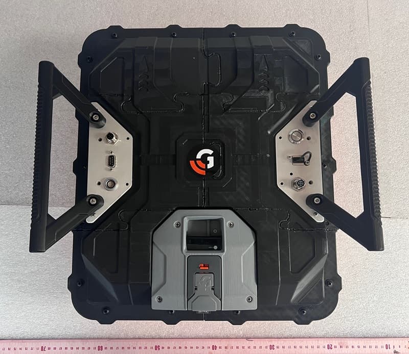
QF7NX0410
Apr 22, 2026GPR Compass NX NX04/10
Equipment Class
UWB - Ultra Wideband Transmitter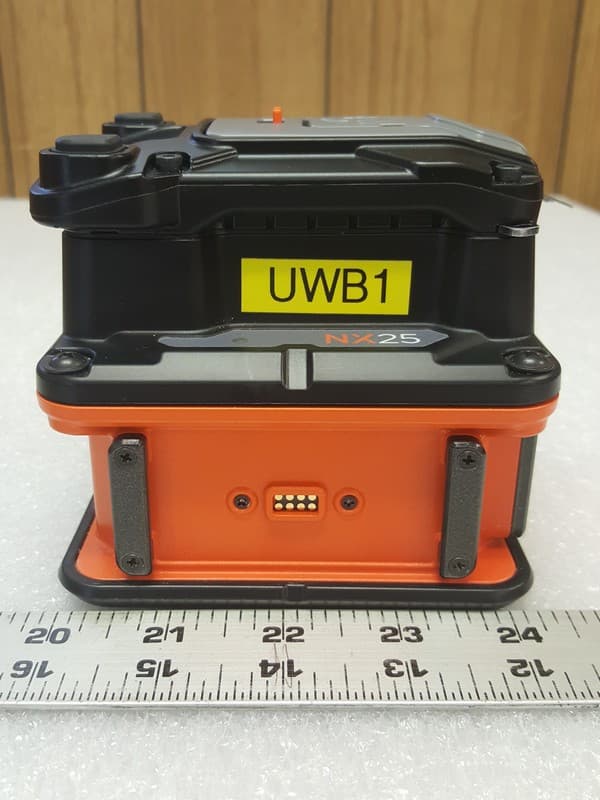
QF7NX25
Aug 30, 2023GPR NX25
Equipment Class
UWB - Ultra Wideband Transmitter
QF7D50300800
Dec 10, 2012Ground Penetrating Radar Antenna
Equipment Class
UWB - Ultra Wideband Transmitter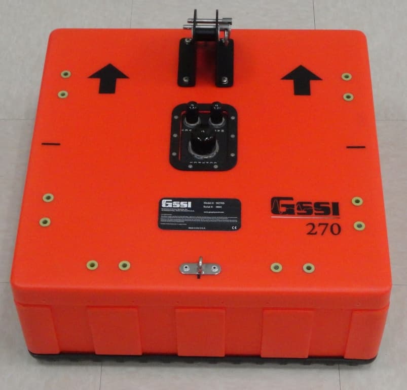
QF750270S
Oct 25, 2012Ground Penetrating Radar Antenna
Equipment Class
UWB - Ultra Wideband Transmitter
QF7MINIHR
Dec 27, 2011Ground penetrating radar
Equipment Class
UWB - Ultra Wideband Transmitter