QFFLLIBCRAMDERFRF Tag
PDM Industries, LLC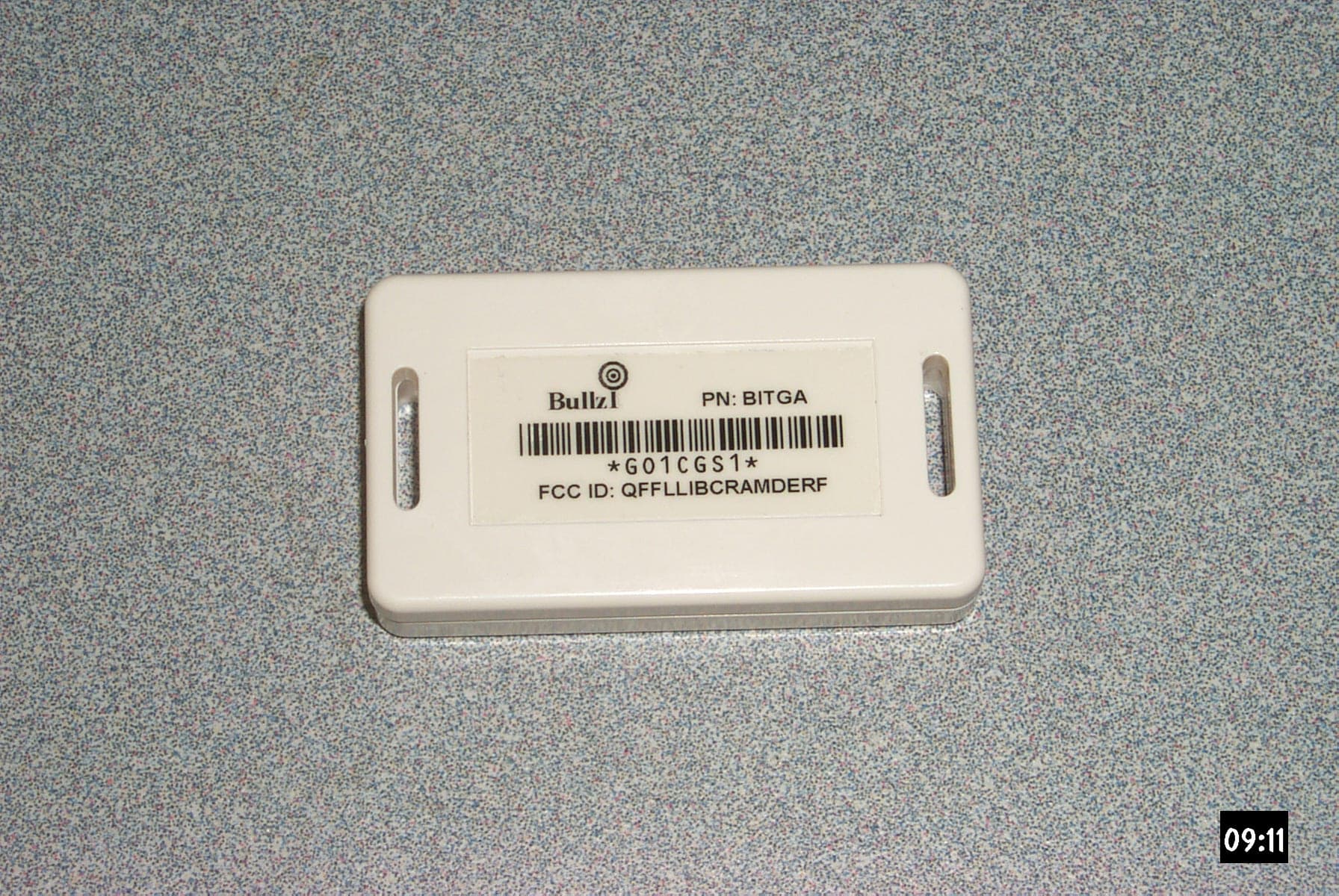
Click to zoom
Application Details
- Equipment Class
- DSC - Part 15 Security/Remote Control Transmitter
- Date of Grant
- Jul 30, 2002
- Application Purpose
- Original Equipment
- Date of Application
- Jul 30, 2002
- Equipment Note
- RF Tag
- Frequency Range
- 303.82500000 - 303.82500000
- Company
- PDM Industries, LLC
- Country
- United States
Documents & Files
Document Text
Text extracted from the exhibit documents filed with the FCC. Open a document above to read the original.
Users Manual
ActaView Software Operation Manual (Preliminary) i FCC Notices The four components of the BullzI Asset Tracking System, as listed below, have been found to comply with Part 15 of the FCC Rules. Operation is subject to the following two conditions: 1. The system may not cause harmful interference. 2. The system must accept any interference received, including interference that may cause undesired operation. Collector, Model BICLA Note: This equipment has been tested and found to comply with the limits for a Class B digital device, pursuant to Part 15 of the FCC Rules. These limits are designed to provide reasonable protection against harmful interference when the equipment is operated in a commercial environment. This equipment generates, uses and can radiate radio frequency energy and, if not installed and used in accordance with the instruction manual, may cause harmful interference to radio communications. Operation of this equipment in a residential area is likely to cause harmful interference in which case the user will be required to correct the interference at his own expense. Shielded Cables: Connections between the Collector and peripherals must be made using shielded cables in order to maintain compliance with FCC radio frequency emission limits. Modifications: Any modifications made to this device that are not approved by PDM Corporation may void the authority granted to the user by the FCC to operate this equipment. Serial Switch, Model BISSA Note: This equipment has been tested and found to comply with the limits for a Class A digital device, pursuant to Part 15 of the FCC Rules. These limits are designed to provide reasonable protection against harmful interference when the equipment is operated in a commercial environment. This equipment generates, uses and can radiate radio frequency energy and, if not installed and used in accordance with the instruction manual, may cause harmful interference to radio communications. Operation of this equipment in a residential area is likely to cause harmful interference in which case the user will be required to correct the interference at his own expense. Shielded Cables: Connections between the Serial Switch and peripherals must be made using shielded cables in order to maintain compliance with FCC radio frequency emission limits. Networking connections can be made using unshielded twisted-pair (UTP) cables. Modifications: Any modifications made to this device that are not approved by PDM Corporation may void the authority granted to the user by the FCC to operate this equipment. Receiver Processor, Model BIRPA13 Note: This equipment has been tested and found to comply with the limits for a Class B digital device, pursuant to Part 15 of the FCC Rules. These limits are designed to provide reasonable protection against harmful interference when the equipment is operated in a commercial environment. This equipment generates, uses and can radiate radio frequency energy and, if not installed and used in accordance with the instruction manual, may cause harmful interference to radio communications. Operation of this equipment in a residential area is likely to cause harmful interference in which case the user will be required to correct the interference at his own expense. Shielded Cables: Connections between the Receiver Processor and peripherals must be made using shielded cables in order to maintain compliance with FCC radio frequency emission limits. Modifications: Any modifications made to this device that are not approved by PDM Corporation may void the authority granted to the user by the FCC to operate this equipment. BullzI RFID Tag, Models BITGA-12, BITGA-25, BITGA-50 FCC ID: QFFLLIBCRAMDERF Note: BullzI tags have been certified in accordance with Part 15 of the FCC Rules. Operation is subject to the following two conditions: 1. The system may not cause harmful interference. 2. The system must accept any interference received, including interference that may cause undesired operation. Modifications: Any modifications made to this device that are not approved by PDM Corporation may void the authority granted to the user by the FCC to operate this equipment. ii Introduction ....................................................................................................... 1 ADMINISTRATIVE MODULE ........................................................................... 2 Starting BullzI Administrator ...................................................................... 2 Adding a Tagged Asset ............................................................................... 3 Deleting a Tagged Asset ............................................................................ 4 Modifying a Tagged Asset ........................................................................... 6 LOCATION VIEWER MODULE ........................................................................ 8 Starting BullzI Location Viewer ................................................................... 8 Asset Viewer ............................................................................................. 9 Location Tree ............................................................................................ 10 Major Category Viewer ........................................................................................ 11 Search by Description, Model or Owner ................................................................ 12 Search by Asset Number or Tag ID ....................................................................... 13 Level Two Search ................................................................................................ 15 Major Category Viewer Window ........................................................................... 16 2D Viewer .......................................................................................................... 17 2D Viewer Operation ..............................................................…
Text truncated - open the document above for the full version.
Cover Letter(s)
PO BOX 33580 CLEVELAND OH 44133-3580 PH (440) 230-2839 FAX (440) 230-5058 PDM Industries, LLC July 25, 2002 Federal Communications Commission 7435 Oakland Mills Road COLUMBIA MD 21046 Dear Sir or Madam: In accordance with Section 0.457(d)(i) pertaining to confidential material, PDM Industries, LLC would like to request confidentiality regarding the submission for FCC ID: QFFLLIBCRAMDERF. The following documents contain trade secrets which would not normally be available to competitors and the general public. •Theory of Operation •Block Diagram •Schematic Diagram We understand that confidentiality does not apply to pictures / photographs. Sincerely, Fred M. Davis Fred Davis Vice President, Engineering
Cover Letter(s)
24 July 2002 RE: PDM Industries FCC ID: QFFLLIBCRAMDERF Response Item 1: The corrected exhibits have been uploaded. Item 2: Thank you for pointing out this oversight; the test setup photos have been uploaded. Item 3: 46dBuV/m was used because it is the general limit for the frequencies in question. The EUT complied with that limit, I have edited the report to use the correct limit, as you pointed out. Item 4: After the plot used in the report is made, any peaks in excess of or near the limits are measured again. It is the second measurement that is used as a final measurement. The initial measurement, using a spectrum analyzer set to 1MHz bandwidth with unknown sweep time was 73.9dBuV/m. The final measurement was made with a CISPR 16 compliant receiver set to 1MHz bandwidth with a measurement time of 2 seconds. The maximum reading was 72.85dBuV/m. Doug Kramer NCEE NCEE NEBRASKA CENTER FOR EXCELLENCE IN ELECTRONICS 4740 Discovery Drive Lincoln, NE 68521 402-472-5880
Cover Letter(s)
American Telecommunications Certification Body Inc. 6731 Whittier Ave, McLean, VA 22101 July 30, 2002 RE: PDM Industries, LLC. FCC ID: QFFLLIBCRAMDERF After a review of the submitted information, I have a few comments on the above referenced Application. 1) The duty cycle given in the theory of operation and test report is miscalculated. The final value should be corrected by 20 log (.122 * 49/100) = -24.5 dB. Please provide corrected exhibits. 2) Please provide a separate exhibit for test configuration photographs. 3) Please explain the use of the limits of 46 dBuV/m for 607.74 & 911.58 MHz. Shouldn't the limit be 53.9 dBuV/m for these frequencies? 4) The plot (page 11 of 20) for > 1 GHz seems to show the 1.519 GHz reading appears higher than the tabular data reported as 72.85 dBuV/m. Please note that the peak limit is considered to be 73.9 dBuV/m. Please comment. Timothy R. Johnson Examining Engineer mailto: [email protected] The items indicated above must be submitted before processing can continue on the above referenced application. Failure to provide the requested information may result in application termination. Correspondence should be considered part of the permanent submission and may be viewed from the Internet after a Grant of Equipment Authorization is issued. Please do not respond to this correspondence using the email reply button. In order for your response to be processed expeditiously, you must submit your documents through the AmericanTCB.com website. Also, please note that partial responses increase processing time and should not be submitted. Any questions about the content of this correspondence should be directed to the sender.
Internal Photos
PDM INDUSTRIES, LLC FCC ID: QFFLLIBCRAMDERF June 9, 2002 BullzI Tag, PCB Component Side, X3 Magnification BullzI Tag, Bottom / Battery Holder Side, X3 Magnification
Test Report
R062602-01A FCC ID: QFFLLIBCRAMDERF NCEE NEBRASKA CENTER FOR EXCELLENCE IN ELECTRONICS 4740 Discovery Drive Lincoln, NE 68521 402-472-5880 Amendment to Test Report R062602-01 Company: PDM Industries 805Galvin Road South #100 Bellevue, NE 68005 Contact: Fred Davis Product: BullzI RF Tag, BITGA-12, 25 and 50 FCC ID: QFFLLIBCRAMDERF Test Report No: R062602-01A APPROVED BY: Steve Cass _________________________ General Manager Doug Kramer _________________________ Test Engineer DATE: 31 July 2002 Total Pages: 20 The Nebraska Center for Excellence in Electronics (NCEE) authorizes the above named company to reproduce this report provided it is reproduced in its entirety for use by the company’s employees only. Any use that a third party makes of this report, or any reliance on or decisions made based on it, are the responsibility of such third parties. NCEE accepts no responsibility for damages, if any, suffered by any third party as a result of decisions made or actions based on this report. This report applies only to the items tested. NCEE is a FCC registered lab. Registration #100875 NCEE R062602-01A FCC ID: QFFLLIBCRAMDERF Page 2 of 20 Table of Contents 1.0 Summary of test results 1.1 Test Results 1.2 Test Methods 1.3 Reason for amended report 2.0 Description 2.1 Equipment under test 2.1.1 Identification 2.1.2 EUT received date 2.1.3 EUT tested date 2.1.4 Manufacturer 2.1.5 Serial number 2.2 Laboratory description 2.3 Special equipment or setup 3.0 Test equipment used 4.0 Detailed Results 4.1 FCC Part 15.203 4.2 FCC Part 15.231e Appendix A – Test setup photos Appendix B – Emissions results Appendix C – Sample Calculation NCEE R062602-01A FCC ID: QFFLLIBCRAMDERF Page 3 of 20 1.0 Summary of test results 1.1 Test Results The EUT was shown to comply with the guidelines for intentional radiators according to Parts 15.203, 15.209 and 15.231e. See Section 4 for more detailed information. 1.2 Test Methods The equipment was tested to comply with CFR 47, Part 15, for intentional radiators. The EUT was tested in accordance to methods of ANSI/IEEE C63.4, 2001. The configuration of the EUT was varied to maximize emissions. All measurements were made at a distance of 3 meters; the antenna height was varied from 1 meter to 4 meters. Both antenna polarizations were examined. The orientation of the EUT was first examined to determine in which position the EUT produced the greatest emissions. New batteries were used. 1.3 Reason for amended report Modifications from the original report have been made in order to better clarify the measurement results. 2.0 Description 2.1 Equipment under test The BullzI RF tags are for use with the BullzI asset tracking system. There are three models of tags each with a different duration between transmissions, the shortest duration being 12 seconds. 2.1.1 Identification: BullzI RF Tag, BITGA-0 (test unit), 2, 12 and 25 2.1.2 EUT received date: 22 July 2002 2.1.3 EUT tested date: 22 July 2002 2.1.4 Manufacturer: PDM Industries, Bellevue, NE 2.1.5 Serial numbers: BITGA-12, SN: C100100; BITGA-25, SN: GO1CGS1; BITGA-0, SN: test1; BITGA-2, SN: 1C1C1C1 2.2 Laboratory description All testing was performed at the NCEE Lincoln facility, which is a FCC registered lab. This site has been fully described in a report submitted to the FCC, and accepted in a letter dated May 4, 2001. Laboratory environmental conditions varied slightly throughout the tests: Relative humidity of 56 ± 5% Temperature of 24 ± 3° Celsius NCEE R062602-01A FCC ID: QFFLLIBCRAMDERF Page 4 of 20 2.3 Special equipment or setup Two tags were modified to transmit more frequently than once per 10-second interval. One unit was set to transmit continuously. The second, SN: 1C1C1C1 was set to transmit at a 2 second interval. 3.0 Test equipment used Serial # Manufacturer Model Description Last cal. 1654 EMCO 3142B Biconilog antenna 3-May-02 6415 EMCO 3115 DRG Horn ant. 24-Oct-01 100037 Rohde & Schwarz ESIB26 EMI Test Receiver 11-Jun-02 082001/003 Rohde & Schwarz TS-PR18 Preamplifier 10-Aug-01 2575 Rohde & Schwarz ES-K1 Software v1.60 N/A 4.0 Detailed Results 4.1 FCC Part 15.203 The antenna is incorporated into the printed circuit board and there are no connectors attached to it or leading into the case. The plastic case is sealed against moisture. Thus the EUT complies with part 15.203. 4.2 FCC Part 15.231e The EUT, SN: test1, was used to first find the orientation of the EUT that provided the worst case. The emissions from the unit were then examined from 30MHz to 4GHz. The antenna was positioned 3m from the EUT and the antenna position was varied between 1 and 4 meters as the EUT was rotated on the turntable. Figures 1 through 3 show the test setup that provided a worst-case configuration. Figure 3 is the EUT in its plastic case as configured for final measurements. A table showing the final results is shown below. All measurements were taken using a quasi-peak detector set to 120kHz bandwidth for measurements under 1GHz, for measurements over 1GHz an average detector set to 1MHz bandwidth was used. An averaging factor was applied to the measurements. The BullzI tag ID Code is an 896 bit binary number. All tag ID Codes are unique and always have forty-nine (49) bits (of the 896 bits) in the “1” state. The tag only transmits these forty-nine (49) bits. The period of one bit is 122.04μs, therefore: Maximum Transmission Duration = 896 bits X 122.04μs / bit = 109.3 mSec In the worst case, some BullzI tag ID Codes will be transmitted in slightly less than 100mSec. Therefore: Ave = Pk - [20log((Pw*N)/100mS)] Where: Ave = Calculated average fundamental field strength in dBμv/m NCEE R062602-01A FCC ID: QFFLLIBCRAMDERF Page 5 of 20 Pk = Peak Corrected Field Strength Measurement in dBμv/m Pw = Transmitted Pulse Width in milliseconds N = Number of pulses in a 100 millisecond window, worst case Assuming the transmitted pulse width equals the modulating pulse width then: Pw = 122 μS, N = 49 Ave = Pk - [20log((.122 * 49) / 100)] Ave = P…
Text truncated - open the document above for the full version.
Contact Information
Applicant
Fred M Davis(Vice President of Engineering)
Technical Contact
PDM Industries, LLC.Fred Davis
[email protected]402-898-1500
805 GALVIN ROAD SOUTH, SUITE 100 · BELLEVUE, Nebraska · United States
Non-Technical Contact
PDM Industries, LLC.Fred Davis
[email protected]402-898-1500
Test Firm
Nebraska Center for Excellence in ElectronicsSteve Cass
Technical Specifications
| # | Rule Parts | Frequency Range | Power Output |
|---|---|---|---|
| 1 | 15.231(e) | 303.825 MHz - 303.825 MHz | - |