QGK-DT100DT-ZM-100MW-WC Spread Spectrum System
Demarc Technology Group, LLC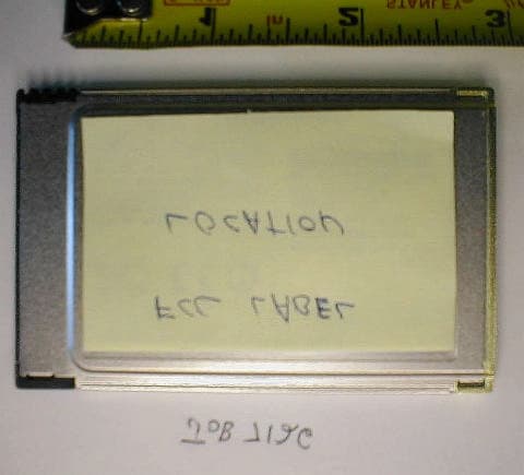
Click to zoom
Application Details
- Equipment Class
- DTS - Digital Transmission System
- Date of Grant
- Dec 19, 2002
- Application Purpose
- Original Equipment
- Date of Application
- Dec 19, 2002
- Equipment Note
- DT-ZM-100MW-WC Spread Spectrum System
- Frequency Range
- 2412.00000000 - 2462.00000000
- Company
- Demarc Technology Group, LLC
- Country
- United States
Documents & Files
Document Text
Text extracted from the exhibit documents filed with the FCC. Open a document above to read the original.
Users Manual
FCC ID NO: QGK-DT-100 Demarc Technology Group, LLC 40 Fairview Rd – Frenchtown NJ, 08825 Tel: 908-996-7995 Fax: 908-847-0202 Website: http:/// www.demarctech.com Email: [email protected] FCC Notice Demarc Technology Group, LLC wireless equipment described herein complies with FCC radiation exposure limits set forth for an uncontrolled environment when installed as directed. The equipment should be installed and operated as fix-mounted system such that the main lobe(s) of these antennas are located a minimum of 8 feet between the antenna and all persons during normal operation. This device complies with Part 15 of the FCC rules. Operation is subject to the following two conditions: 1. This device may not cause harmful interference. 2. This device must accept any interference received, including interference that may cause undesired operation. Changes or modifications not expressly approved by the manufacturer could void the user’s authority to operate the equipment. Federal Communications Commission (FCC) Statement This Equipment has been tested and found to comply with the limits for a Class B digital device, pursuant to Part 15 of the FCC rules. These limits are designed to provide reasonable protection against harmful interference in a residential installation. This equipment generates, uses, and can radiate radio frequency energy and, if not installed and used in accordance with the instructions, may cause harmful interference to radio communications. However, there is no guarantee that interference will not occur in a particular installation. FCC Output Power Restrictions The FCC does not require licensing to implement this device. However, the FCC has established restrictions regarding maximum output power and the adjustments required when employing directional gain antennas. These restrictions are detailed in FCC Part 15.247 (b)(1), (b)(3)(i), and (3)(iii). It is the responsibility of the individuals designing and implementing the radio system to assure compliance with these and any other pertinent FCC Rules and Regulations. FCC RF Radiation Exposure Statement: The DT-ZM-100mW-WC is designed for 2.4 GHz @ 100mW. This level of RF energy are below the Maximum Permissible Exposure (MPE) levels specified in FCC OET 65:97-01. This is only approved with the antenna gains as listed in this document with the maximum antenna gain of 15.7dBi. A separation distance of 25 cm between the antenna and humans must be maintained. The following precautions must be taken during installation of this equipment: • The installed antenna must not be located in a manner that allows exposure of the general population to the direct beam path of the antenna at a distance less than 25cm. Installation on towers, masts, or rooftops not accessible to the general population is recommended; or • Mount the antenna in a manner that prevents any personnel from entering the area within 25 cm from the front of the antenna. • During antenna installation, be sure that power to the DT-ZM-100mW-WC equipment is turned off in order to prevent any energy presence on the coaxial connector. • During installation and alignment of the antenna, do not stand in front of the antenna assembly. • During installation and alignment of the antenna, do not handle or touch the front of the antenna. These simple precautions must be taken to prevent personnel from exposure to RF energy in excess of specified MPE levels. FCC ID NO: QGK-DT-100 Demarc Technology Group, LLC 40 Fairview Rd – Frenchtown NJ, 08825 Tel: 908-996-7995 Fax: 908-847-0202 Website: http:/// www.demarctech.com Email: [email protected] Feedline Loss Feedline loss is a function of feedline type and length. Feedline loss per 100 feet for several types of coax at 2.4Ghz is detailed in the table below. The RF loss applies to BBP/RFC interconnection, and the RF loss applies to RFC/antenna interconnection. RF Loss per 100 feet at 2.4GHz Cable dB Loss/100 feet LMR-100 40 dB LMR-195 19 dB LMR-200 16.9 dB LMR-240 12.9 dB LMR-300 10.4 dB LMR-400 6.8 dB LMR-500 5.48 dB LMR-600 4.42 dB LMR-900 2.98 dB LMR-1200 2.26 dB LMR-1700 1.71 dB TRANSMITTER POWER The FCC specifies the maximum transmitter power that may be used for antennae of a given gain. FCC rules Part 15, Subpart 247 allow for a maximum power of 1 watt into antennae of a gain less than or equal to 6 dBi. For every 1 dB of gain over 6 dBi, the transmitter must be reduced by 1 dB. FCC ID NO: QGK-DT-100 Demarc Technology Group, LLC 40 Fairview Rd – Frenchtown NJ, 08825 Tel: 908-996-7995 Fax: 908-847-0202 Website: http:/// www.demarctech.com Email: [email protected] Authorized Antennas and Antenna Gain Best performance will result from the use of high gain antennas. DT-ZM-100mW-WC is intended to be coupled with an antenna that is directional and provides signal gain as the FCC provides no recourse in this band in the event of nearby interference, so a highly directional antenna reduces the likelihood of interference in the antenna pattern. A unique style (reverse MMCX) connector is provided on the DT-ZM-100mW-WC to prevent the use of non-approved antennas. The following table is a list of Demarc antenna models that are approved to be used with this device: All antennas are the same type antenna. Only the panel design is changed between the different models. The Omni directional antennas do not have panels installed. Model No. Frequency Mhz Gain dBi HB/VB Degree Model No. Frequency Mhz Gain dBi HB/VB Degree 180° Sector Panel Base Station Antennas (Vertical) Omni Directional Base Station Antennas (Vertical) SPDG11H 2400-2483 3.5 180/70 SPDG11O 2400-2483 2 360/90 SPDG12H 2400-2483 6 180/40 SPDG12O 2400-2483 4.5 360/55 SPDG13H 2400-2483 7.5 180/24 SPDG13O 2400-2483 5.5 360/30 SPDG14H 2400-2483 8 180/20 SPDG14O 2400-2483 6.5 360/24 SPDG16H 2400-2483 9.5 180/14 SPDG16O 2400-2483 8 360/18 SPDG18H 2400-2483 10.5 180/10 SPDG112H 2400-2483 11.5 180/8 Omni Directional Base Station Antennas (Vertical) (Panel) SPDG12OP 2400-2483 4.5 360/5…
Text truncated - open the document above for the full version.
Cover Letter(s)
American Telecommunications Certification Body Inc. 6731 Whittier Ave, McLean, VA 22101 October 14, 2002 RE: FCC ID: QGK-DT100 Attention: I have a few comments on this Application. 1 Please note, I can find no reference to a grantee code of QGK on the FCC server. Also please note that there is no listing showing that Demarc Technologies Group, LLC has a grantee code. Please correct all documentation to provide the correct grantee code, or alternately please obtain a grantee code for Demarc Technologies Group, LLC and provide corrected documentation showing a valid grantee code. 2 Please note that a ‘release’ letter is insufficient for access to schematics and other information held confidential by the FCC. Also, please note that the ID reference provided does not seem to exist. Please provide the information in the form of an exhibit to ATCB. The following files will need to be uploaded to the ATCB server in order to proceed: Confidential Schematics, confidential Block Diagrams. 3 Please note the 731 form states that this device operates in the 2400 MHZ ISM band. However, your MPE states compliance to 15.407 (UNII) band. Please correct the appropriate documentation to reflect the correct operating frequency range and MPE conditions. 4 Please note, certain documents claim that this device is professionally installed. However, this is a PCMCIA card usable in any PCMCIA slot. Professional installation indicates that a one- time installation process is involved. Please note that a PCMCIA format card is intended for repetitive or at least multiple installation and reinstallation. What is to prevent the user from keeping the PCMCIA card and using a standard antenna connected to this device in other locations, applications, etc.? Please explain how it is possible for a PCMCIA card to be limited to professional installations. Alternately, please correct all appropriate documentation to remove any indication of professional installation and provide the unit with a unique connector. 5 The manual does not contain the appropriate statement in accordance with 15.21 (Information to user). The ‘no unauthorized modification’ statement must be provided in the manual. Please correct the manual to include this statement. 6 Please note, ANSI C63.4 is not the proper test method for Spread Spectrum devices. DSSS devices should be tested in accordance with FCC97114 or equivalent. Please provide indicate testing was performed using this or similar FCC accepted test methods for SS devices. 7 Your report states the use of an Omni-Directional antenna of 17.8dBi. However, the manual says this is a 45d degree Sector Panel antenna. Please correct the reference to the type antenna used to be consistent. Dennis Ward mailto:[email protected] The items indicated above must be submitted before processing can continue on the above referenced application. Failure to provide the requested information may result in application termination. Correspondence should be considered part of the permanent submission and may be viewed from the Internet after a Grant of Equipment Authorization is issued. Please do not respond to this correspondence using the email reply button. In order for your response to be processed expeditiously, you must submit your documents through the AmericanTCB.com website. Also, please note that partial responses increase processing time and should not be submitted. l Page 2October 14, 2002 Any questions about the content of this correspondence should be directed to the sender.
Cover Letter(s)
American Telecommunications Certification Body Inc. 6731 Whittier Ave, McLean, VA 22101 October 22, 2002 RE: FCC ID: QGK-DT100 Attention: Gregory M. Snyder / Brian J. Dettling I have a few comments on this Application. 1 The manual states 8 feet separation from antenna. This disagrees with the MPE calculations. Please coincide the separation distances that will be on the grant. (Please note, since the max gain of the antenna must cause the power to be reduced by 2.3dB [see item 3], the max MPE would be less than 20cm anyway [i.e.18dBi ant 18dB power = 17.8cm distance]. This means the standard 20cm separation statement would be adequate for this device and should be used on the grant) 2 The manual states, "A unique style (reverse MMCX) connector is provided on the DT-ZM- 100mW-WC to prevent the use of non-approved or high gain antennas." Please note, the antenna(s) used in the report are high gain antenna(s). The statement therefore is confusing as to the intent. Please restate the manual to prevent the use of non-approved antennas. 3 The defacto power including antenna gain of 15.247 devices is 36dBm, or the one watt delivered to the antenna + a 6dBi gain antenna (30dBm + 6Dbi = 36dBm). Please note that the use of the 18 dBi gain antenna puts the device over the defacto limit of 36dB. The highest power measured was 20.3dBm. Since this system cannot be used as an exclusive point to point system, this means that the highest gain antenna that can be used to meet the defacto power is or 15.7 dBi (36-20.3). You must either reduce the conducted power delivered to the antenna on this device by 2.3dBm for use with an 18 dBi gain antenna or you must reduce the maximum antenna gain allowable with the device to 15.7dBi. 4 How is the label permanently affixed to the device? 5 You reference schematics to be used in a previous grant. This reference (M4Y325H1) does not exist. There is an FCC ID file for M4Y-3251 and a file for M4Y-0325H. But no reference to the FCC ID number specifically mentioned in the letter exists. Please provide either the schematics, or the proper designation for the FCC ID involved. Dennis Ward mailto:[email protected] The items indicated above must be submitted before processing can continue on the above referenced application. Failure to provide the requested information may result in application termination. Correspondence should be considered part of the permanent submission and may be viewed from the Internet after a Grant of Equipment Authorization is issued. Please do not respond to this correspondence using the email reply button. In order for your response to be processed expeditiously, you must submit your documents through the AmericanTCB.com website. Also, please note that partial responses increase processing time and should not be submitted. Any questions about the content of this correspondence should be directed to the sender.
Cover Letter(s)
Response to ATCB Comments 10.22.02 FCC ID: QGK-DT100 1 Washington Laboratories, Ltd. 7560 LINDBERGH DRIVE GAITHERSBURG, MD 20879 (301) 417 – 0220 FAX # (301) 417 - 9069 November 6, 2002 Mr. Dennis Ward American Telecommunications Certification Body Inc. 6731 Whittier Ave McLean, VA 22101 RE: Comments of October 22, 2002 APPLICATION: FCC ID: QGK-DT100 Demarc Technologies Group, LLC Dear Mr. Ward: Below are the comments that you have provided regarding the application for certification referenced above. Our responses to those comments are in bold italic. Many responses refer you to additional exhibit(s) which has been uploaded to the application folder at the ATCB website. Thank you for your attention. Please feel free to contact us for any additional information that you may require. Regards, Gregory M. Snyder Chief EMC Engineer, Wireless/Telco Services Manager Brian J. Dettling Documentation Specialist WLL Project: 7165 October 14, 2002 RE: FCC ID: QGK-DT100 Attention: Gregory M. Snyder / Brian J. Dettling 1) The manual states 8 feet separation from antenna. This disagrees with the MPE calculations. Please coincide the separation distances that will be on the grant. (Please note, since the max gain of the antenna must cause the power to be reduced by 2.3dB [see item 3], the max MPE would be less than 20cm anyway [i.e.18dBi ant 18dB power = 17.8cm distance]. This means the standard 20cm separation statement would be adequate for this device and should be used on the grant). Response to ATCB Comments 10.22.02 FCC ID: QGK-DT100 2 R. The manual has been updated to correct the separation distance to the 25 cm as listed in the MPE report. Please see exhibit “100MW User Guide Rev 2.pdf”. 2) The manual states, "A unique style (reverse MMCX) connector is provided on the DT-ZM-100mW- WC to prevent the use of non-approved or high gain antennas." Please note, the antenna(s) used in the report are high gain antenna(s). The statement therefore is confusing as to the intent. Please restate the manual to prevent the use of non-approved antennas. R. The statement is the User’s Manual has been amended. 3) The defacto power including antenna gain of 15.247 devices is 36dBm, or the one watt delivered to the antenna + a 6dBi gain antenna (30dBm + 6Dbi = 36dBm). Please note that the use of the 18 dBi gain antenna puts the device over the defacto limit of 36dB. The highest power measured was 20.3dBm. Since this system cannot be used as an exclusive point to point system, this means that the highest gain antenna that can be used to meet the defacto power is or 15.7 dBi (36-20.3). You must either reduce the conducted power delivered to the antenna on this device by 2.3dBm for use with an 18 dBi gain antenna or you must reduce the maximum antenna gain allowable with the device to 15.7dBi. R. With antenna gains of more than 15 dBi are only to be used at client site for point-to-point applications. The User’s Manual has been updated to reflect this. 4) How is the label permanently affixed to the device? R. The manufacturer attests that the label is printed on Mylar, and is applied with a permanent, pressure-sensitive adhesive. 5) You reference schematics to be used in a previous grant. This reference (M4Y325H1) does not exist. There is an FCC ID file for M4Y-3251 and a file for M4Y-0325H. But no reference to the FCC ID number specifically mentioned in the letter exists. Please provide either the schematics, or the proper designation for the FCC ID involved. R. Please see previously uploaded exhibit “ZComax Release Letter Amendment.pdf” which gives the correct FCC ID of M4Y-325H2.
Cover Letter(s)
Response to ATCB Comments FCC ID: QGK-DT100 1 Washington Laboratories, Ltd. 7560 LINDBERGH DRIVE GAITHERSBURG, MD 20879 (301) 417 – 0220 FAX # (301) 417 - 9069 October 22, 2002 Mr. Dennis Ward American Telecommunications Certification Body Inc. 6731 Whittier Ave McLean, VA 22101 RE: Comments of October 14, 2002 APPLICATION: FCC ID: QGK-DT100 Demarc Technologies Group, LLC Dear Mr. Ward: Below are the comments that you have provided regarding the application for certification referenced above. Our responses to those comments are in bold italic. Many responses refer you to additional exhibit(s) which has been uploaded to the application folder at the ATCB website. Thank you for your attention. Please feel free to contact us for any additional information that you may require. Regards, Gregory M. Snyder Chief EMC Engineer, Wireless/Telco Services Manager Brian J. Dettling Documentation Specialist WLL Project: 7165 October 14, 2002 1) Please note, I can find no reference to a grantee code of QGK on the FCC server. Also please note that there is no listing showing that Demarc Technologies Group, LLC has a grantee code. Please correct all documentation to provide the correct grantee code, or alternately please obtain a grantee code for Demarc Technologies Group, LLC and provide corrected documentation showing a valid grantee code. R. The Grantee Code, which was previously dismissed due to a processing error, has been restored and is valid as provided. Response to ATCB Comments FCC ID: QGK-DT100 2 2) Please note that a ‘release’ letter is insufficient for access to schematics and other information held confidential by the FCC. Also, please note that the ID reference provided does not seem to exist. Please provide the information in the form of an exhibit to ATCB. The following files will need to be uploaded to the ATCB server in order to proceed: Confidential Schematics, confidential Block Diagrams. R. A letter referencing the original release letter has been prepared to revise errors and clarify the required exhibits. Please see exhibit “ZComax Release Letter Amendment.pdf”. 3) Please note the 731 form states that this device operates in the 2400 MHZ ISM band. However, your MPE states compliance to 15.407 (UNII) band. Please correct the appropriate documentation to reflect the correct operating frequency range and MPE conditions. R. A revised MPE report has been prepared, however, no reference to a U-NII device was noted. Please see exhibit “DEM7165 MPE Rev 1.pdf”. 4) Please note, certain documents claim that this device is professionally installed. However, this is a PCMCIA card usable in any PCMCIA slot. Professional installation indicates that a one-time installation process is involved. Please note that a PCMCIA format card is intended for repetitive or at least multiple installation and reinstallation. What is to prevent the user from keeping the PCMCIA card and using a standard antenna connected to this device in other locations, applications, etc.? Please explain how it is possible for a PCMCIA card to be limited to professional installations. Alternately, please correct all appropriate documentation to remove any indication of professional installation and provide the unit with a unique connector. R. The device is being supplied with a unique connector and will not be professionally installed. The test report, MPE report, and manual have been updated to reflect this. 5) The manual does not contain the appropriate statement in accordance with 15.21 (Information to user). The ‘no unauthorized modification’ statement must be provided in the manual. Please correct the manual to include this statement. R. The statement has been added to the revised manual. Please see exhibit “100MW User Guide Rev 1.pdf”. 6) Please note, ANSI C63.4 is not the proper test method for Spread Spectrum devices. DSSS devices should be tested in accordance with FCC97114 or equivalent. Please provide indicate testing was performed using this or similar FCC accepted test methods for SS devices. R. The revised test report now lists the FCC97114 guidance in the referenced documents. Please see exhibit “DEM7165X Test Report Rev 1.pdf”. 7) Your report states the use of an Omni-Directional antenna of 17.8dBi. However, the manual says this is a 45d degree Sector Panel antenna. Please correct the reference to the type antenna used to be consistent. R. The revised test report has been updated to properly list the antenna used for this device.
External Photos
Top View Bottom View Interface Side View Antenna Side View
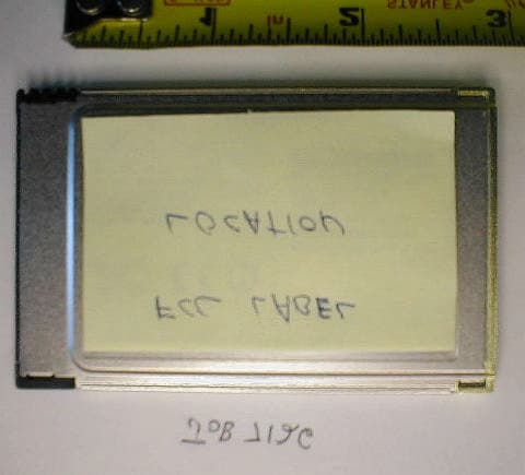
ID Label/Location Info
FCCID:QGK-DT100 ThisdevicecomplieswithPart15ofFCCRules. OperationisSubjecttothefollowingconditions: (1)devicemaynotcauseharmfulinterference, and(2)thisdevicemustacceptany thatmaycauseundesiredoperation. interference ! MadeinTaiwan http://www.demarctech.com
Internal Photos
Covers Off, Showing Shields In Place Disassembled (Some Shields Removed) PCB Top (Some Shields Removed) Top, All Shields Removed PCB Bottom View
RF Exposure Info
Maximum Permissible Exposure Test Report for Demarc Technologies Group, LLC FCC ID: QGK-100MW-PCM October 17, 2002 WLL PROJECT #: 7165RFFCC This report may not be reproduced, except in full, without the prior written consent of Washington Laboratories, Ltd. Demarc Technologies FCC ID: QGK-100MW-PCM WLL Project #: 7165RFFCC 1 Maximum Permissible Exposure Test Report for Demarc Technologies Group, LLC FCC ID: QGK-100MW-PCM 1.0 Introduction This report has been prepared on behalf of Demarc Technologies Group, LLC. to show compliance with the RF exposure requirements of FCC Part 15.407(f) as defined in FCC Part 1.1307(b)(1) for the Demarc Wireless LAN card. 3.8 Radio Frequency Radiation Exposure In accordance with Section 1.1310 of the FCC rules, the Maximum Permissible Exposure (MPE) limit for this frequency range is 1mW/cm 2 for General Population/Uncontrolled Access. The EUT is designed for telecommunications transmissions and may use high gain antennas (up to 18 dBi) and the transmitter section is designed for mounting on an antenna mast. A unique connector is used on the card to prevent the use of higher gain antennas. Warnings are in the installation manual which limit the exposure to the direct beam during installation and maintenance. These warnings to the installers insure that the general public is not exposed to RF energy. The Demarc Wireless LAN card is designed for a transmit power of 20.3dBm (107mW). Assuming the highest allowable gain antenna is used (18 dBi) the following power density is calculated. S = (PG)/(4πR 2 ) Where, S = Power Density P = Output Power at the Antenna Terminals G = Gain of Transmit Antenna (linear gain) R = Distance from Transmitting Antenna For this device, the calculation is as follows: S = FCC Limit = 1mW/cm 2 P = Output Power = 107mW G = Worst Case Gain = 18 dBi (65 linear gain) R = 25 cm Demarc Technologies FCC ID: QGK-100MW-PCM WLL Project #: 7165RFFCC 2 S = {(107mW)(65}/{(12.56)(625 cm 2 )} = 0.88 mW/cm 2 This power density is the worst case for maximum beam exposure. This level is below the limit of 1mW/cm 2 MPE for general population/uncontrolled access. This unit is installed in practice to installations at distances greater than 25 cm from humans. Warnings are provided in the installation manual to limit exposure to the direct beam during the installation and maintenance phase. These warnings ensure that the device is installed properly and does not expose the general public to RF energy hazards.
Test Report
Document 7165-01, Rev. 1 FCC Certification Test Report Washington Laboratories, Ltd October 2002 FCC Certification Test Report for Demarc Technologies Group, LLC QGK-DT100 October 8, 2002 Prepared for: Demarc Technologies Group, LLC 40 Fairview Road Frenchtown, NJ 08825 Prepared By: Washington Laboratories, Ltd. 7560 Lindbergh Drive Gaithersburg, Maryland 20879 FCC Certification Test Report Document 7165-01, Rev. 1 FCC Certification Test Report Washington Laboratories, Ltd October 2002 FCC Certification Test Report for the Demarc Technologies Group, LLC DT-ZM-100MW-WC 2.4 GHz DSSS QGK-DT100 WLL JOB# 7165 Prepared by: Brian J. Dettling Documentation Specialist Reviewed by: Mike Violette President Document 7165-01, Rev. 1 FCC ID: QGK-DT100 FCC Certification Test Report Washington Laboratories, Ltd October 2002 ii Abstract This report has been prepared on behalf of Demarc Technologies Group, LLC to support the attached Application for Equipment Authorization. The test report and application are submitted for a Spread Spectrum Transceiver under Part 15.247 of the FCC Rules and Regulations. This Federal Communication Commission (FCC) Certification Test Report documents the test configuration and test results for a Demarc Technologies Group, LLC DT-ZM-100MW-WC 2.4 GHz DSSS. Testing was performed on an Open Area Test Site (OATS) of Washington Laboratories, Ltd, 7560 Lindbergh Drive, Gaithersburg, MD 20879. Site description and site attenuation data have been placed on file with the FCC's Sampling and Measurements Branch at the FCC laboratory in Columbia, MD. Washington Laboratories, Ltd. has been accepted by the FCC and approved by NIST NVLAP (NVLAP Lab Code: 200066-0) as an independent FCC test laboratory. The Demarc Technologies Group, LLC DT-ZM-100MW-WC 2.4 GHz DSSS complies with the limits for a Spread Spectrum Transceiver device under Part 15.247 of the FCC Rules and Regulations. Document 7165-01, Rev. 1 FCC ID: QGK-DT100 FCC Certification Test Report Washington Laboratories, Ltd October 2002 iii Table of Contents Abstract......................................................................................................ii 1 Introduction...................................................................................................................1 1.1 Compliance Statement............................................................................................1 1.2 Test Scope............................................................................................................1 1.3 Contract Information..............................................................................................1 1.4 Test Dates.............................................................................................................1 1.5 Test and Support Personnel....................................................................................1 1.6 Abbreviations.........................................................................................................2 2 Equipment Under Test....................................................................................................3 2.1 EUT Identification & Description............................................................................3 2.2 Test Configuration..................................................................................................3 2.3 Testing Algorithm...................................................................................................4 2.4 Test Location.........................................................................................................4 2.5 Measurements........................................................................................................4 2.5.1 References.....................................................................................................4 2.6 Measurement Uncertainty.......................................................................................5 3 Test Equipment..............................................................................................................6 4 Test Results...................................................................................................................7 4.1 RF Power Output..................................................................................................7 4.2 Power Spectral Density........................................................................................11 4.3 Occupied Bandwidth............................................................................................11 4.4 Spurious Emissions at Antenna Terminals (FCC Part §15.247(b)).........................15 4.5 Radiated Spurious Emissions: (FCC Part §15.247(c))...........................................34 4.5.1 Test Procedure............................................................................................34 4.6 AC Powerline Conducted Emissions: (FCC Part §15.207)...................................43 Document 7165-01, Rev. 1 FCC ID: QGK-DT100 FCC Certification Test Report Washington Laboratories, Ltd October 2002 iv List of Tables Table 1. Device Summary....................................................................................................3 Table 2. Test Equipment List................................................................................................6 Table 3. RF Power Output...................................................................................................7 Table 4. Power Spectral Density........................................................................................11 Table 5. Occupied Bandwidth Results................................................................................15 Table 6. Radiated Emission Test Data (§15.205 Restricted Bands).....................................36 Table 7. Radiated Emission Test Data (§15.205 Restricted Bands).....................................38 Table 8. Radiated Emission Test Data (§15.205 Res…
Text truncated - open the document above for the full version.
Test Report
Document 7165-01, Rev. 1 FCC ID: QGK-DT100 FCC Certification Test Report Washington Laboratories, Ltd October 2002 Page 21 of 44 Figure 12. Spurious Emissions Data- Channel 1, 18GHz – 27GHz Document 7165-01, Rev. 1 FCC ID: QGK-DT100 FCC Certification Test Report Washington Laboratories, Ltd October 2002 Page 22 of 44 Figure 13. Spurious Emissions Data- Channel 6, Fundamental Document 7165-01, Rev. 1 FCC ID: QGK-DT100 FCC Certification Test Report Washington Laboratories, Ltd October 2002 Page 23 of 44 Figure 14. S…
Text truncated - open the document above for the full version.
Contact Information
Applicant
Anthony R Morella(CEO)
Technical Contact
Washington Laboratories, Ltd.Gregory M Snyder
[email protected]301/ 417-0220
7560 Lindbergh Drive · Gaithersburg, Maryland · United States
Non-Technical Contact
Washington Laboratories, Ltd.Brian J Dettling
[email protected]301/ 417-0220
Test Firm
Washington Laboratories, Ltd.Michael Violette
Technical Specifications
| # | Rule Parts | Frequency Range | Power Output |
|---|---|---|---|
| 1 | 15C | 2.41 GHz - 2.46 GHz | 107.00 mW |
Other Applications from Demarc Technology Group, LLC
QGK-DT200
Sep 08, 2003PCMCIA WLAN Card
Equipment Class
DTS - Digital Transmission System