QGMCDWClay Delay Transmitter
Opticom, Inc.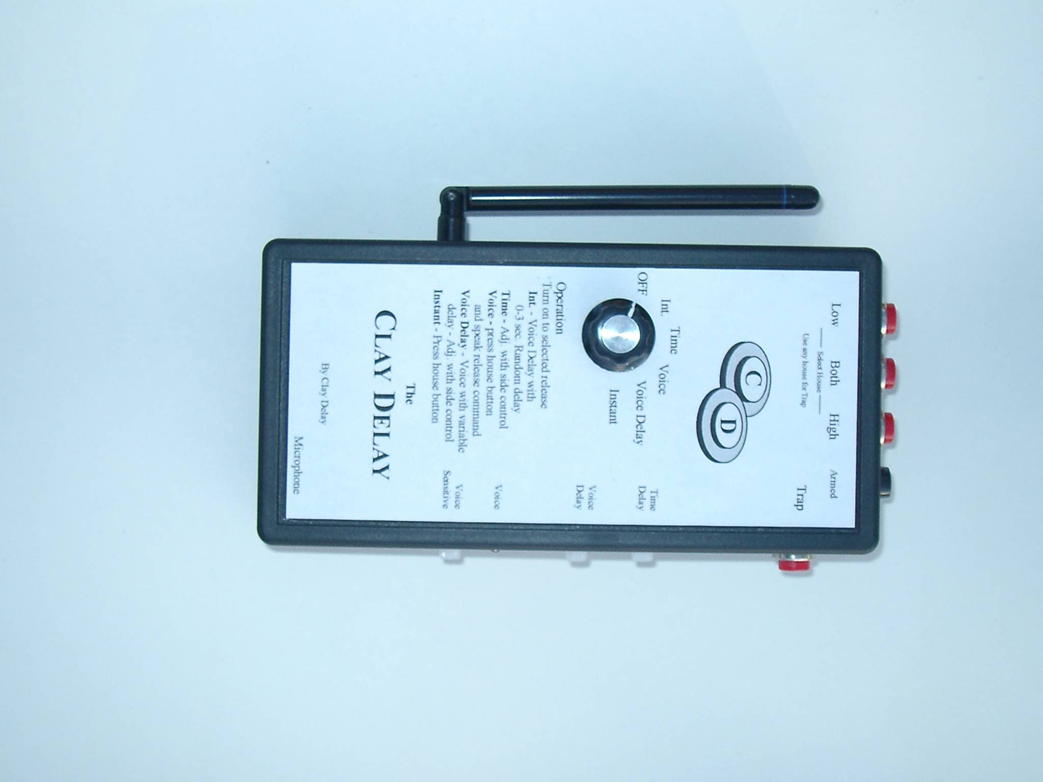
Click to zoom
Application Details
- Equipment Class
- DSC - Part 15 Security/Remote Control Transmitter
- Date of Grant
- Nov 05, 2002
- Application Purpose
- Original Equipment
- Date of Application
- Nov 05, 2002
- Equipment Note
- Clay Delay Transmitter
- Frequency Range
- 418.00000000 - 418.00000000
- Company
- Opticom, Inc.
- Country
- United States
Documents & Files
Document Text
Text extracted from the exhibit documents filed with the FCC. Open a document above to read the original.
Cover Letter(s)
Barry Quinlan From: "Frank Santucci" <[email protected]> To: "Curtis-Straus TCB" <[email protected]> Sent: Thursday, October 31, 2002 11:43 PM Sub ject: Re: FCC ID: QGMCDW Page 1 of 2 11/5/2002 Hello Barry, We will send over a better copy of the data requested in item 1. For item 2, the pulse length is preset and fixed it does not change. The statement is refering to the receiver time that it takes to activate switch on machine. It may need to be re written. For item 3, I am talking with Gary at Xerox to try and resolve. Is the issue still valid based on the answer for item 2? Frank Santucci CEO / OPTICOM INC. --- Curtis-Straus TCB <certification@curtis -straus.com> wrote: > Hi Frank, > > We have identified these issues following our review > of the application: > > 1. Please re-send figures 1 & 2 of the test report > as we are unable see them. > > 2. The manual indicates that the pulse length of the > units transmission is adjustable. Please tell us > the maximum pulse length generated by the > transmitter. > > 3. In the test report the method of developing the > average readings appears unacceptable. The average > values of field strength must be developed from the > peak field strength readings using a conversion > factor calculated from the worst case 100mS pulse > train. Please present information as to the worst > case pulse train duty cycle over 100mS. See > 15.35(c). > > Best regards > > Barry C. Quinlan > Certification Manager > Curtis-Straus TCB > > __________________________________________________ Do you Yahoo!? HotJobs - Search new jobs daily now htt p://hotjobs.yahoo.com/ Page 2 of 2 11/5/2002
Contact Information
Applicant
Frank C Santucci(Owner)
Test Firm
Xerox CorporationGary Myers
Technical Specifications
| # | Rule Parts | Frequency Range | Power Output |
|---|---|---|---|
| 1 | 15.231 | 418 MHz - 418 MHz | - |