QHUAMRF01RF Module
Ameleks Corporation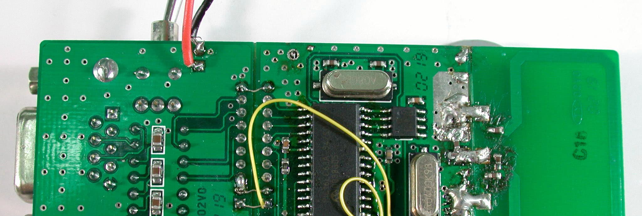
Click to zoom
Application Details
- Equipment Class
- DSC - Part 15 Security/Remote Control Transmitter
- Date of Grant
- Sep 03, 2002
- Application Purpose
- Original Equipment
- Date of Application
- Sep 03, 2002
- Equipment Note
- RF Module
- Frequency Range
- 433.92000000 - 433.92000000
- Company
- Ameleks Corporation
- Country
- Taiwan
Documents & Files
Document Text
Text extracted from the exhibit documents filed with the FCC. Open a document above to read the original.
Users Manual
RFMO-0201 6F, 48, KEELUNG ROAD, SEC. 2, TAIPEI 110, TAIWAN, R.O.C. TEL: 886-2-2758-6958FAX: 886-2-2758-6987E-MAIL: [email protected]: http://www.ameleks.com 1 AMELEKS CORP. MICROWAVE COMPONENTS DISTRIBUTION FOR ASIAN TELECOMMUNICATIONS INDUSTRY General Description The most significant difference between wireless link and wired link is that the wireless one is free from the cable installation and operating under the regulated distance. Once the wireless solution is designed in, product or device may apply in various phases, floors and high-elevated locations with appropriated power saving solution and installation. RFMO-0201 is a complete RF board with a protocol-on-micro-processor structure and without extra driver installation, which is designed to replace the cable between the PC and the peripheral RS-232 equipments and make data transmitted over radio. RFMO-0201 uses 433.92 free-licensed ISM band. RFMO-0201 is designed to interface with RS-232 port, with its featured compact size it can be installed or embedded in various handheld devices. s Note 1: Max 2 characters are allowed in every single transmission. s Note 2: This product is utilized for control purpose. Continuous data transmission will not be adopted. s Note 3: The duration of each transmission shall not be greater than one second and the silent period between transmissions shall be at least 30 times the duration of the transmission but in no case less than 10 seconds. Product Features n FCC Certified n Max. Output Power 1mW n RF Sensitivity: –102dBm n Communication Range: 5 ~ 60 meters n UART Data Rate: 9.6K bps n 433.92 MHz ISM Band n 2 Level FSK Modulation n Embedded Micro Processor and UART Interface n Optional On-board 50Ω PCB Loop Antenna n TDMA Access Application n Security Device: Car Alarm, Home Security, RF ID n Remote Automation: Remote Control, Home Automation n Wireless Sensing: Weather Monitoring n Long Range Control n Wireless Data Log: Telemetry RFMO-0201 6F, 48, KEELUNG ROAD, SEC. 2, TAIPEI 110, TAIWAN, R.O.C. TEL: 886-2-2758-6958FAX: 886-2-2758-6987E-MAIL: [email protected]: http://www.ameleks.com 2 AMELEKS CORP. MICROWAVE COMPONENTS DISTRIBUTION FOR ASIAN TELECOMMUNICATIONS INDUSTRY General Description Radio Frequency 433.92MHZ Modulation Type 2-level FSK Number of channel One channel TDMA Performance RF Transmission Data Rate 16.2Kbps UART Data Rate 9.6Kbps (Inter-communication) Output Power 1mW Sensitivity -102 ~ -99dBm at 16.2kbps 10 -1 BER Communication range 5 ~ 60m line of sight Power Requirement Supply Voltage 3.3 ~ 5.0 Vdc Transmit Current Consumption 10 ~ 17mA Standby Current Consumption < 60uA Antenna Optional On Board Loop Antenna, 50 terminal Physical Properties Board size (Without ANT) 34 x 34 x 8 (mm) Connect Pitch 2.0mm Operating Temperature -10 ~ 65 Pin Configuration Connector: PIN 1: VCC Supply Voltage 5V PIN 2: GND PIN 3: FAIL Fail active Low PIN 4: SUC Success active Low PIN 5: STB Standby active Low PIN 6: RX UART Receiver pin PIN 7: TX UART Transmitter pin PIN 8: TEST Test Pin Pull Low before power on will be into the Test mode Pull Hi will be release the test mode PIN 9: MASTER/SLAVE Mode change pin Low=SLAVE mode Hi=MASTER mode PIN 10: GND RFMO-0201 6F, 48, KEELUNG ROAD, SEC. 2, TAIPEI 110, TAIWAN, R.O.C. TEL: 886-2-2758-6958FAX: 886-2-2758-6987E-MAIL: [email protected]: http://www.ameleks.com 3 AMELEKS CORP. MICROWAVE COMPONENTS DISTRIBUTION FOR ASIAN TELECOMMUNICATIONS INDUSTRY Time Out Sequence with Programming Format Data stream < 30 bytes ' 1' 32 ms Tx (RS232) Rx(RS232) FAIL pin Time scale time out:1s STB pin one ASCII byte 31(H) SUC pin one ASCII byte 30(H) 32 ms >10s Operation Mode & Jumper Setting RFMO-0201 6F, 48, KEELUNG ROAD, SEC. 2, TAIPEI 110, TAIWAN, R.O.C. TEL: 886-2-2758-6958FAX: 886-2-2758-6987E-MAIL: [email protected]: http://www.ameleks.com 4 AMELEKS CORP. MICROWAVE COMPONENTS DISTRIBUTION FOR ASIAN TELECOMMUNICATIONS INDUSTRY Important Notice Devices operated under the provisions of this paragraph shall be provided with a means for automatically limiting operation so that the duration of each transmission shall not be greater than one second and the silent period between transmissions shall be at least 30 times the duration of the transmission but in no case less than 10 seconds. Federal Communication Commission Interference Statement This equipment has been tested and found to comply with the limits for a Class B digital device, pursuant to Part 15 of the FCC Rules. These limits are designed to provide reasonable protection against harmful interference in a residential installation. This equipment generates, uses and can radiate radio frequency energy and, if not installed and used in accordance with the instructions, may cause harmful interference to radio communications. However, there is no guarantee that interference will not occur in a particular installation. If this equipment does cause harmful interference to radio or television reception, which can be determined by turning the equipment off and on, the user is encouraged to try to correct the interference by one of the following measures: - Reorient or relocate the receiving antenna. - Increase the separation between the equipment and receiver. - Connect the equipment into an outlet on a circuit different from that to which the receiver is connected. - Consult the dealer or an experienced radio/ TV technician for help. This device complies with Part 15 of the FCC Rules. Operation is subject to the following two conditions: (1) This device may not cause harmful interference, and (2) this device must accept any interference received, including interference that may cause undesired operation. Information to User – The users manual or instruction manual for an intentional or unintentional radiator shall caution the user that changes or modifications not expressly approved by the party responsible for compliance could void the user’s authority to operate the equipment.
Users Manual
RFMO-0201 6F, 48, KEELUNG ROAD, SEC. 2, TAIPEI 110, TAIWAN, R.O.C. TEL: 886-2-2758-6958FAX: 886-2-2758-6987E-MAIL: [email protected]: http://www.ameleks.com 1 AMELEKS CORP. MICROWAVE COMPONENTS DISTRIBUTION FOR ASIAN TELECOMMUNICATIONS INDUSTRY General Description RFMO-0201 is a complete RF board with a protocol-on-micro-processor structure and without extra driver installation, which is designed to replace the cable between the peripheral and the peripheral and make signal transmitted over radio. RFMO-0201 uses 433.92 free-licensed ISM band. RFMO-0201 is designed to interface with RS-232 port, with its featured compact size it can be installed or embedded in various handheld devices. s Note 1: Max 2 characters are allowed in every single transmission. s Note 2: This product is utilized for control purpose. Continuous data transmission will not be adopted. s Note 3: The duration of each transmission shall not be greater than one second and the silent period between transmissions shall be at least 30 times the duration of the transmission but in no case less than 10 seconds. Product Features n FCC Certified n Max. Output Power 10dBm n RF Sensitivity: –102dBm n Communication Range: 5 ~ 60 meters n UART Data Rate: 9.6K bps n 433.92 MHz ISM Band n 2 Level FSK Modulation n Embedded Micro Processor and UART Interface n Optional On-board 50Ω PCB Loop Antenna n TDMA Access Application n Simple Robotic Control System RFMO-0201 6F, 48, KEELUNG ROAD, SEC. 2, TAIPEI 110, TAIWAN, R.O.C. TEL: 886-2-2758-6958FAX: 886-2-2758-6987E-MAIL: [email protected]: http://www.ameleks.com 2 AMELEKS CORP. MICROWAVE COMPONENTS DISTRIBUTION FOR ASIAN TELECOMMUNICATIONS INDUSTRY General Description Radio Frequency433.92MHZ Modulation Type2-level FSK Number of channelOne channel TDMA Performance RF Transmission Data Rate16.2Kbps UART Data Rate9.6Kbps (Inter-communication) Output Power1mW Sensitivity-102 ~ -99dBm at 16.2kbps 10 -1 BER Communication range5 ~ 60m line of sight Power Requirement Supply Voltage3.3 ~ 5.0 Vdc Transmit Current Consumption10 ~ 17mA Standby Current Consumption< 60uA Antenna OptionalOn Board Loop Antenna, 50 terminal Physical Properties Board size (Without ANT)34 x 34 x 8 (mm) Connect Pitch2.0mm Operating Temperature-10 ~ 65 Pin Configuration Connector: PIN 1: VCCSupply Voltage 5V PIN 2: GND PIN 3: FAILFail active Low PIN 4: SUCSuccess active Low PIN 5: STBStandby active Low PIN 6: RXUART Receiver pin PIN 7: TXUART Transmitter pin PIN 8: TESTTest Pin Pull Low before power on will be into the Test mode Pull Hi will be release the test mode PIN 9: MASTER/SLAVEMode change pin Low=SLAVE mode Hi=MASTER mode PIN 10: GND RFMO-0201 6F, 48, KEELUNG ROAD, SEC. 2, TAIPEI 110, TAIWAN, R.O.C. TEL: 886-2-2758-6958FAX: 886-2-2758-6987E-MAIL: [email protected]: http://www.ameleks.com 3 AMELEKS CORP. MICROWAVE COMPONENTS DISTRIBUTION FOR ASIAN TELECOMMUNICATIONS INDUSTRY Time Out Sequence with Programming Format Data stream < 30 bytes ' 1' 32 ms Tx (RS232) Rx(RS232) FAIL pin Time scale time out:1s STB pin one ASCII byte 31(H) SUC pin one ASCII byte 30(H) 32 ms >10s RFMO-0201 6F, 48, KEELUNG ROAD, SEC. 2, TAIPEI 110, TAIWAN, R.O.C. TEL: 886-2-2758-6958FAX: 886-2-2758-6987E-MAIL: [email protected]: http://www.ameleks.com 4 AMELEKS CORP. MICROWAVE COMPONENTS DISTRIBUTION FOR ASIAN TELECOMMUNICATIONS INDUSTRY Operation Mode & Jumper Setting FCC DoC Label AMELEKSRFMO-0201 RFMO-0201 6F, 48, KEELUNG ROAD, SEC. 2, TAIPEI 110, TAIWAN, R.O.C. TEL: 886-2-2758-6958FAX: 886-2-2758-6987E-MAIL: [email protected]: http://www.ameleks.com 5 AMELEKS CORP. MICROWAVE COMPONENTS DISTRIBUTION FOR ASIAN TELECOMMUNICATIONS INDUSTRY Important Notice Devices operated under the provisions of this paragraph shall be provided with a means for automatically limiting operation so that the duration of each transmission shall not be greater than one second and the silent period between transmissions shall be at least 30 times the duration of the transmission but in no case less than 10 seconds. Federal Communication Commission Interference Statement This equipment has been tested and found to comply with the limits for a Class B digital device, pursuant to Part 15 of the FCC Rules. These limits are designed to provide reasonable protection against harmful interference in a residential installation. This equipment generates, uses and can radiate radio frequency energy and, if not installed and used in accordance with the instructions, may cause harmful interference to radio communications. However, there is no guarantee that interference will not occur in a particular installation. If this equipment does cause harmful interference to radio or television reception, which can be determined by turning the equipment off and on, the user is encouraged to try to correct the interference by one of the following measures: - Reorient or relocate the receiving antenna. - Increase the separation between the equipment and receiver. - Connect the equipment into an outlet on a circuit different from that to which the receiver is connected. - Consult the dealer or an experienced radio/ TV technician for help. FCC Caution: Any changes or modifications not expressly approved by the party responsible for compliance could void the user's authority to operate this equipment. This device complies with Part 15 of the FCC Rules. Operation is subject to the following two conditions: (1) This device may not cause harmful interference, and (2) this device must accept any interference received, including interference that may cause undesired operation. RFMO-0201 6F, 48, KEELUNG ROAD, SEC. 2, TAIPEI 110, TAIWAN, R.O.C. TEL: 886-2-2758-6958FAX: 886-2-2758-6987E-MAIL: [email protected]: http://www.ameleks.com 6 AMELEKS CORP. MICROWAVE COMPONENTS DISTRIBUTION FOR ASIAN TELECOMMUNICATIONS INDUSTRY IMPORTANT NOTE: FCC Radiation Exposure Statement: This equipment complies with FCC radiation exposure limits set forth for an unco…
Text truncated - open the document above for the full version.
Users Manual
RFMO-0201 6F, 48, KEELUNG ROAD, SEC. 2, TAIPEI 110, TAIWAN, R.O.C. TEL: 886-2-2758-6958FAX: 886-2-2758-6987E-MAIL: [email protected]: http://www.ameleks.com 1 AMELEKS CORP. MICROWAVE COMPONENTS DISTRIBUTION FOR ASIAN TELECOMMUNICATIONS INDUSTRY General Description The most significant difference between wireless link and wired link is that the wireless one is free from the cable installation and operating under the regulated distance. Once the wireless solution is designed in, product or device may apply in various phases, floors and high-elevated locations with appropriated power saving solution and installation. RFMO-0201 is a complete RF board with a protocol-on-micro-processor structure and without extra driver installation, which is designed to replace the cable between the PC and the peripheral RS-232 equipments and make data transmitted over radio. RFMO-0201 uses 433.92 free-licensed ISM band. RFMO-0201 is designed to interface with RS-232 port, with its featured compact size it can be installed or embedded in various handheld devices. s Note 1: Max 2 characters are allowed in every single transmission. s Note 2: This product is utilized for control purpose. Continuous data transmission will not be adopted. s Note 3: The duration of each transmission shall not be greater than one second and the silent period between transmissions shall be at least 30 times the duration of the transmission but in no case less than 10 seconds. Product Features n FCC Certified n Max. Output Power 1mW n RF Sensitivity: –102dBm n Communication Range: 5 ~ 60 meters n UART Data Rate: 9.6K bps n 433.92 MHz ISM Band n 2 Level FSK Modulation n Embedded Micro Processor and UART Interface n Optional On-board 50Ω PCB Loop Antenna n TDMA Access Application n Security Device: Car Alarm, Home Security, RF ID n Remote Automation: Remote Control, Home Automation n Wireless Sensing: Weather Monitoring n Long Range Control n Wireless Data Log: Telemetry RFMO-0201 6F, 48, KEELUNG ROAD, SEC. 2, TAIPEI 110, TAIWAN, R.O.C. TEL: 886-2-2758-6958FAX: 886-2-2758-6987E-MAIL: [email protected]: http://www.ameleks.com 2 AMELEKS CORP. MICROWAVE COMPONENTS DISTRIBUTION FOR ASIAN TELECOMMUNICATIONS INDUSTRY General Description Radio Frequency 433.92MHZ Modulation Type 2-level FSK Number of channel One channel TDMA Performance RF Transmission Data Rate 16.2Kbps UART Data Rate 9.6Kbps (Inter-communication) Output Power 1mW Sensitivity -102 ~ -99dBm at 16.2kbps 10 -1 BER Communication range 5 ~ 60m line of sight Power Requirement Supply Voltage 3.3 ~ 5.0 Vdc Transmit Current Consumption 10 ~ 17mA Standby Current Consumption < 60uA Antenna Optional On Board Loop Antenna, 50 terminal Physical Properties Board size (Without ANT) 34 x 34 x 8 (mm) Connect Pitch 2.0mm Operating Temperature -10 ~ 65 Pin Configuration Connector: PIN 1: VCC Supply Voltage 5V PIN 2: GND PIN 3: FAIL Fail active Low PIN 4: SUC Success active Low PIN 5: STB Standby active Low PIN 6: RX UART Receiver pin PIN 7: TX UART Transmitter pin PIN 8: TEST Test Pin Pull Low before power on will be into the Test mode Pull Hi will be release the test mode PIN 9: MASTER/SLAVE Mode change pin Low=SLAVE mode Hi=MASTER mode PIN 10: GND RFMO-0201 6F, 48, KEELUNG ROAD, SEC. 2, TAIPEI 110, TAIWAN, R.O.C. TEL: 886-2-2758-6958FAX: 886-2-2758-6987E-MAIL: [email protected]: http://www.ameleks.com 3 AMELEKS CORP. MICROWAVE COMPONENTS DISTRIBUTION FOR ASIAN TELECOMMUNICATIONS INDUSTRY Time Out Sequence with Programming Format Data stream < 30 bytes ' 1' 32 ms Tx (RS232) Rx(RS232) FAIL pin Time scale time out:1s STB pin one ASCII byte 31(H) SUC pin one ASCII byte 30(H) 32 ms >10s Operation Mode & Jumper Setting RFMO-0201 6F, 48, KEELUNG ROAD, SEC. 2, TAIPEI 110, TAIWAN, R.O.C. TEL: 886-2-2758-6958FAX: 886-2-2758-6987E-MAIL: [email protected]: http://www.ameleks.com 4 AMELEKS CORP. MICROWAVE COMPONENTS DISTRIBUTION FOR ASIAN TELECOMMUNICATIONS INDUSTRY Important Notice Devices operated under the provisions of this paragraph shall be provided with a means for automatically limiting operation so that the duration of each transmission shall not be greater than one second and the silent period between transmissions shall be at least 30 times the duration of the transmission but in no case less than 10 seconds. Federal Communication Commission Interference Statement This equipment has been tested and found to comply with the limits for a Class B digital device, pursuant to Part 15 of the FCC Rules. These limits are designed to provide reasonable protection against harmful interference in a residential installation. This equipment generates, uses and can radiate radio frequency energy and, if not installed and used in accordance with the instructions, may cause harmful interference to radio communications. However, there is no guarantee that interference will not occur in a particular installation. If this equipment does cause harmful interference to radio or television reception, which can be determined by turning the equipment off and on, the user is encouraged to try to correct the interference by one of the following measures: - Reorient or relocate the receiving antenna. - Increase the separation between the equipment and receiver. - Connect the equipment into an outlet on a circuit different from that to which the receiver is connected. - Consult the dealer or an experienced radio/ TV technician for help. This device complies with Part 15 of the FCC Rules. Operation is subject to the following two conditions: (1) This device may not cause harmful interference, and (2) this device must accept any interference received, including interference that may cause undesired operation. Information to User – The users manual or instruction manual for an intentional or unintentional radiator shall caution the user that changes or modifications not expressly approved by the party responsible for compliance could void the user’s authority to operate the equipment.
Cover Letter(s)
AMELEKS Corporation 6F,No.48, Keelung Rd., Sec.2,Taipei, Taiwan, R.O.C. TEL.:+886+2-2758-6958 FAX:+886+2-2758-6987 Inform Letter Dear Customer, According to FCC’s regulation, the following Declaration of Conformity has to be made by a company located in USA. They are: This device has been confirmed to be in compliance with the requirements of ANSI C63.4 & FCC part 15 regulations. The test result has been shown in the ADT test report with number RF910617R01. And this compliance is subject to the following two conditions: (1) This device may not cause harmful interference and, (2) This device must accept any interference received, including interference that may cause undesired operation. This declaration can be a separate sheet and be sure that the following message will be also included in this declaration: 1) Product name, model name and trade name. 2) Company name, and address of the one who is responsible for this declaration. 3) Name, title, telephone and fax number as well as the signature of the contact person. Thanks for your attention.
Cover Letter(s)
Please note that the following comments have been added to the Users Manual for clarification. The Users manual must be opened in Adobe reader 5. The users manual, Block Diagram and schematics heave been provided in response to Correspondence Reference Number 5372. • Note 1: Max 2 characters are allowed in every single transmission. • Note 2: This product is utilized for control purpose. Continuous data transmission will not be adopted. • Note 3: The duration of each transmission shall not be greater than one second and the silent period between transmissions shall be at least 30 times the duration of the transmission but in no caseless than 10 seconds. Please note that the descriptions in the Block diagram and Schematics were incorrect from the manufacturer. The designation for this device is RF Module, not RF Modem. Respectfully ATCB
External Photos
Page 1 ANNEX PHOTOGRAPHS OF EUT Page 2
ID Label/Location Info
MODEL NO: RFMO-0201 FCC ID: QHUAMRF01 THIS UNIT COMPLIES WITH PART 15 OF FCC RULES. SEE INSTRUCTIONS OF MANUAL. 2 CM 2 CM
ID Label/Location Info
LABEL LOCATION FOR FCC ID
Internal Photos
Page 3
Operational Description
FCC ID: QHUAMRF01 ADT No.910617R01 Operational Description The transmitter of the EUT (RF Module) is powered by 3V Battery. The transmitter use Integral Antenna. The output power of this device is very low. Under normal use condition, the transmitter and the receiver are quite close, so high EIRP power is neither necessary nor allowed because of interference.
Test Report
FCC ID: QHUAMRF01 Report No.: RF910617R011Issued: August 20, 2002 FCC TEST REPORT REPORT NO.: RF910617R01 MODEL NO.: RFMO-0201 RECEIVED: June 17, 2002 TESTED: August 13 ~ August 15, 2002 APPLICANT:AMELEKS CORP. ADDRESS:6F, 48, KEELUNG ROAD, SEC.2, TAIPEI, TAIWAN, R.O.C. ISSUED BY:Advance Data Technology Corporation LAB LOCATION:47 14th Lin, Chia Pau Tsuen, Linkou Hsiang, Taipei, Taiwan, R.O.C. This test report consists of 16 pages in total. It may be duplicated completely for legal use with the approval of the applicant. It should not be reproduced except in full, without the written approval of our laboratory. The client should not use it to claim product endorsement by NVLAP or any U.S. government agencies. The test results in the report only apply to the tested sample. Lab Code: 200102-0 0528 ILAC MRA FCC ID: QHUAMRF01 Report No.: RF910617R012Issued: August 20, 2002 Table of Contents 1CERTIFICATION.............................................................................................3 2SUMMARY OF TEST RESULTS.....................................................................4 3GENERAL INFORMATION.............................................................................5 3.1GENERAL DESCRIPTION OF EUT...............................................................5 3.2DESCRIPTION OF TEST MODES.................................................................6 3.3GENERAL DESCRIPTION OF APPLIED STANDARDS.................................6 3.4DESCRIPTION OF SUPPORT UNITS............................................................6 4TEST PROCEDURE AND RESULT................................................................7 4.1CONDUCTED EMISSION MEASUREMENT..................................................7 4.2RADIATED EMISSION MEASUREMENT.......................................................7 4.2.1LIMITS OF RADIATED EMISSION MEASUREMENT....................................7 4.2.2TEST INSTRUMENT......................................................................................8 4.2.3TEST PROCEDURE.......................................................................................9 4.2.4TEST SETUP................................................................................................10 4.2.5EUT OPERATING CONDITION....................................................................10 4.2.6TEST RESULT...............................................................................................11 4.3BAND EDGES MEASUREMENT..................................................................13 4.3.1LIMITS OF BAND EDGES MEASUREMENT...............................................13 4.3.2TEST INSTRUMENTS..................................................................................13 4.3.3TEST PROCEDURE.....................................................................................13 4.3.4EUT OPERATING CONDITION....................................................................13 4.3.5TEST RESULTS............................................................................................14 5PHOTOGRAPHS OF THE TEST CONFIGURATION...................................15 6INFORMATION ON THE TESTING LABORATORIES..................................16 FCC ID: QHUAMRF01 Report No.: RF910617R013Issued: August 20, 2002 1 CERTIFICATION PRODUCT : RF Module BRAND NAME : Ameleks MODEL NO : RFMO-0201 APPLICANT : AMELEKS CORP. STANDARDS : 47 CFR Part 15, Subpart C(15.231) ANSI C63.4-1992 We, Advance Data Technology Corporation, hereby certify that one sample of the designation has been tested in our facility from August 13 ~ August 15, 2002. The test record, data evaluation and Equipment Under Test (EUT) configurations represented herein are true and accurate accounts of the measurements of the sample's EMC characteristics under the conditions herein specified. FCC ID: QHUAMRF01 Report No.: RF910617R014Issued: August 20, 2002 2 SUMMARY OF TEST RESULTS The EUT has been tested according to the following specifications: APPLIED STANDARD: 47 CFR Part 15, Subpart C STANDARD PARAGRAPH TEST TYPERESULTREMARK 15.207Conducted Emission TestN/A Power supply is 3VDC from batteries 15.231Radiated Emission TestPASS Minimum passing margin is –11.10dBuV at 1301.00MHz 15.231(c)Occupied Bandwidth TestPASSNA NOTE: The receiver part to communicate with the EUT has been verified to comply with FCC Part 15, Subpart B, Class B (DoC). FCC ID: QHUAMRF01 Report No.: RF910617R015Issued: August 20, 2002 3 GENERAL INFORMATION 3.1 GENERAL DESCRIPTION OF EUT PRODUCTRF Module MODEL NO.RFMO-0201 POWER SUPPLY3VDC from battery MODULATION TYPEFSK CARRIER FREQUENCY OF EACH CHANNEL 433.92MHz BANDWIDTH OF EACH CHANNEL +/-125kHz NUMBER OF CHANNEL1 ANTENNA TYPEIntegral antenna DATA CABLE NA I/O PORTSRS-232 ASSOCIATED DEVICESNA NOTE: 1. Devices operated under the provisions of this paragraph shall be provided with a means for automatically limiting operation so that the duration of each transmission shall not be greater than one second and the silent period between transmissions shall be at least 30 times the duration of the transmission but in no case less than 10 seconds. 2. For more detailed features description of the EUT, please refer to the manufacturer's specifications or the User's Manual. FCC ID: QHUAMRF01 Report No.: RF910617R016Issued: August 20, 2002 3.2 DESCRIPTION OF TEST MODES One channel was provided to this EUT. ChannelFrequency 1433.92MHz 3.3 GENERAL DESCRIPTION OF APPLIED STANDARDS The EUT is the transmitter part of a RF Module. According to the specifications of the manufacturer, it must comply with the requirements of the following standards: FCC CFR 47 Part 15, Subpart C (15.231) ANSI C63.4-1992 All tests have been performed and recorded as per the above standards. 3.4 DESCRIPTION OF SUPPORT UNITS NA FCC ID: QHUAMRF01 Report No.: RF910617R017Issued: August 20, 2002 4 TEST PROCEDURE AND RESULT 4.1 CONDUCTED EMISSION MEASUREMENT NA 4.2 RADIATED EMISSION MEASUREMENT 4.2.1 LIMITS OF RADIATED EMISSION MEASUREMENT Accord…
Text truncated - open the document above for the full version.
Test Setup Photos
FCC ID: QHUAMRF01 Report No.: RF910617R0115Issued: August 20, 2002 5 PHOTOGRAPHS OF THE TEST CONFIGURATION RADIATED EMISSION TEST
Contact Information
Applicant
Mary Tien(Marketing Support)
Technical Contact
Advance Data Technology CorporationAlan Lane
[email protected]+886-3-327-0910
13-1, Lane 19, WenShan 3rd., St., · Taoyuan · Taiwan
Non-Technical Contact
Advance Data Technology CorporationVivi Wang
[email protected]+886-3-327-0910
Test Firm
Bureau Veritas CPS (H.K.) Ltd. Taoyuan BranchTommy Wu
Technical Specifications
| # | Rule Parts | Frequency Range | Power Output |
|---|---|---|---|
| 1 | 15.231 | 433.92 MHz - 433.92 MHz | - |