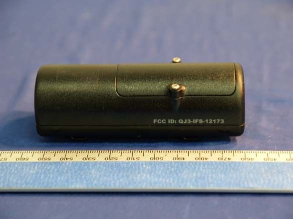
QJ3-IFS-12173Compass System with Wireless Temperature Sensor
PNI Corporation
Click to zoom
Application Details
- Equipment Class
- DXX - Part 15 Low Power Communication Device Transmitter
- Date of Grant
- Jun 14, 2004
- Application Purpose
- Original Equipment
- Date of Application
- Jun 14, 2004
- Equipment Note
- Compass System with Wireless Temperature Sensor
- Frequency Range
- 914.97500000 - 914.97500000
- Company
- PNI Corporation
- Country
- United States
Documents & Files
Document Text
Text extracted from the exhibit documents filed with the FCC. Open a document above to read the original.
Users Manual
V2020usersguideJH4W.doc 1 6/8/2004 9:44 AM WAYFINDER V2020 Manual Copy FRONT COVER: Wayfinder® Full Spectrum™ Temperature and Compass System USER’S GUIDE [insert packaging images] BACK COVER: pni logo PNI Corporation 5464 Skylane Boulevard, Suite A Santa Rosa, CA 95403 USA T – (888) 422-6672 (Customer Service) F – (707) 566-2261 www.pnicorp.com © Copyright 2004. All rights reserved. Wayfinder is a registered trademark and Full Spectrum is a trademark of PNI Corporation. TEXT – SECTION 1: WHAT’S INCLUDED Wayfinder Display Unit Mounting Bracket with suction cups Outside Temperature Sensor 3M Dual Lock industrial Velcro (3 pieces) Cable Ties (Two sets of 2) Two lithium batteries #123 12 volt power cord OPTIONAL: Inside Temperature Sensor [insert illustrations of each component -- #’s 1-8] V2020usersguideJH4W.doc 2 6/8/2004 9:44 AM TEXT – SECTION 2: MOUNTING THE OUTSIDE TEMPERATURE SENSOR The Temperature Sensor’s all-weather performance ensures that it’s water resistant and can withstand extreme temperatures from –40 o to 105 o F. There is no need to remove the Sensor during summer or winter seasons. A. Insert battery 1) Remove the 2 screws from the battery lid on the curved side of the Sensor. 2) Install a lithium battery #123 in the cavity, with the positive (+) polarity facing the near outside edge of the Sensor. 3) Replace the lid and screw down tight. [insert illustration #9 of battery installation] B. Attach to front of vehicle Choose a location underneath or behind your front bumper, or behind your grill, that allows free air circulation and is not affected by direct engine heat or sunlight. 1) Using cable ties: a) Slip the cable ties through the slots on the back of the Temperature Sensor. b) Wrap the ties around the front bumper or a component of the bumper or grill. c) Insert the tail of the cable ties through the slot in the cable tie head, and cinch the ties so the sensor is secure. Clip the loose ends. [insert illustration #10 showing cable ties through slots on back of sensor, and illustration #11 showing sensor attached to bumper.] 2) Using 3M Dual Lock fastener: a) Clean an area underneath or behind your front bumper or grill where you can easily attach the Temperature Sensor. b) Peel the tape shield off one side of the two-piece Dual Lock fastener and attach the locked pieces firmly to the bottom (flat side) of the Sensor. c) Peel the tape shield off the second side of the Dual Lock fastener and attach the Sensor to the cleaned area on your bumper or grill. [insert illustration #12 showing attachment of Dual Lock to Sensor and bumper] NOTE: The sensor can also be placed in your vehicle trunk. The Temperature Sensor will stay on continuously once the battery is installed. Battery life is approximately 3 years. V2020usersguideJH4W.doc 3 6/8/2004 9:44 AM TEXT – SECTION 3: INSTALLING THE INSIDE TEMPERATURE SENSOR (optional item) A. Insert Battery (same as for Outside Temperature Sensor, see section #2) B. Place Inside Vehicle 1) Place the optional Inside Temperature Sensor anywhere inside your vehicle, such as the glove compartment or under your seat. 2) Keep the sensor away from direct sunlight to ensure it reads the true ambient air temperature. NOTE: The Outside Temperature Sensor can be easily converted to an Inside Temperature Sensor by removing the battery cover from the back of the Sensor, and then removing the jumper from the battery cavity. [insert illustration #12.5] TEXT – SECTION 4: MOUNTING THE WAYFINDER® DISPLAY UNIT A. Insert battery 1) Slide open the battery cover on the back of the unit. 2) Insert a lithium battery #123 with the positive (+) polarity facing the top of the unit. 3) Replace the battery cover. [insert illustration #13 showing battery placement in unit] B. Attach bracket 1) Slide the compass into the mounting bracket until it clicks securely into place (it will only fit one way). 2) Adjust the unit on the bracket for optimal viewing angle. a) Hold the unit face down, grasp the bracket handle, and pull it to the right to separate the locking teeth. b) Move bracket to the appropriate position and release the handle to re-engage the teeth. [insert illustration #14 showing bracket adjustment] c) Adjust as needed after mounting. For best viewing, the display should be no more than 20 o from its horizontal position. C. Secure to windshield 1) Find a spot on your windshield that allows easy viewing of both the Wayfinder and the road, and clean well. NOTE: Be sure the location is at least 5 inches away from audio speakers to prevent interference. 2) Press the suction cups firmly against the windshield. D. Button Functions V2020usersguideJH4W.doc 4 6/8/2004 9:44 AM [insert illustration #15 showing display face with buttons, compass reading and temperature readings; also include call-outs for button functions:] ON -- turns the Display Unit on LIGHT -- turns the backlight on and off o F/ o C -- switches between Fahrenheit and Celsius readings SETUP – begins compass setup OFF -- turns the Display Unit off E. Automatic Shut-off Display Unit will shut off automatically after 10 minutes with no perceived change in magnetic field. TEXT – SECTION 5: SETTING UP THE COMPASS The compass must be setup in order to provide accurate readings. Always setup the compass with the Wayfinder Display Unit mounted on your windshield, and in an area where you can easily drive your vehicle in a small circle (such as an empty parking lot or cul-de-sac). 1) When you press the SETUP button, the screen will read, “PRESS SETUP FOR 2 SECS”. 2) Press and hold the SETUP button for 2 seconds. The screen will display “ - - - -“ and then “TURN CAR IN FULL CIRCLE.” 3) Drive your vehicle in one complete circle (any direction). Once you’ve begun the maneuver, the screen will display “PRESS SETUP WHEN DONE”. 4) When you’ve completed the circle, press SETUP. The screen will display “-----“ and then “SETUP DONE”. 5) When you move your Display Unit or change the battery, you will need to setup the co…
Text truncated - open the document above for the full version.
Cover Letter(s)
Federal Communications Commission Authorization and Evaluation Division 06/09/2004 Confidentiality Request regarding application for certification of FCC ID: QJ3-IFS-12173 Pursuant to Sections 0.457 and 0.459 of the Commission’s Rules, we hereby request confidential treatment of information accompanying this application as outlined below: All design related information pertinent to the PNI V2020 Temperature and Compass System including: • Schematics • Block diagrams • Operational Descriptions & Characteristics The above materials contain trade secrets and proprietary information not customarily released to the public. The public disclosure of these materials may be harmful to the applicant and provide unjustified benefits to its competitors. The applicant understands that pursuant to Section 0.457 of the Rules, disclosure of this application and all accompanying documentation will not be made before the date of the Grant for this application. Sincerely, Tony de Rijk VP of Research and Development PNI Corporation
External Photos
EUT – Front View EUT – Rear View
Internal Photos
EUT – Cover Off View I EUT Component View EUT – Cover Off View 2 EUT – Solder View
Test Report
REPORT OF TEST DATA FOR FOR PNI Prepared by Daniel C. Swann June 5, 2004 PNI Wireless Temperature Transmitter PN 12173 GEL File PNI 03-2004 GLEN ELLEN LABORATORIES 1876 London Ranch Road Glen Ellen, CA 95442 GEL File PNI 03-2004PNI PN 12173 Glen Ellen Laboratories 2June 5, 2004 TABLE OF CONTENTS 1.Test Methodology 2.Description of Test Facility 2.1Site Description 2.2Test Equipment List 3.Radiated Emissions Data 3.1Intentional Radiated Emissions 3.2Unintentional Radiated Emissions, Harmonics 3.3Unintentional Radiated Emissions, Other Emissions 3.4Field Strength Calculation for Radiated Emissions 4.0Photographs 4.1Front of Radiated Test Setup 4.2Rear View of Radiated Test Setup This report contains 10 pages GEL File PNI 03-2004PNI PN 12173 Glen Ellen Laboratories 3June 5, 2004 1.Test Methodology The radiated tests were performed in accordance with the procedures specified by ANSI C63.4-2001. Compliance with applicable standards was determined by comparing the measured results with respect to the limits specified in 47CFR Part 15.249 and Part 15.209. These measurements were made on June 3, 2004, by Dan Swann, Tony de Rijk and Anders Boeen, at a distance of 3 meters. Initially, the transmitter was tested at a 1 meter measurement distance on all three axis with 360 degrees of rotation on each axis to determine the direction of maximum emissions. The highest radiation level was obtained when the antenna end of the EUT was directly facing the receive antenna. Therefore, the unit was tested on the open area test site turntable as shown in the photographs of the radiated test setup. Limits were converted from mV/m and uV/m using: Limit in dBuV/meter = 20 * Log (limit in mV/meter * 1000)) = 20 * Log (limit in uV/meter) The limits used were as follows, for a Part 15.249 transmitter in the 902-928 MHz band: Intentional radiator limit, fundamental frequency quasi-peak limit = 50 mV/m at 3 meters = 94 dBuV/m peak limit = 94 dBuV/m + 20 dB = 114 dBuV/m Intentional radiator limit, harmonics of the fundamental frequency average limit = 500 uV/m at 3 meters = 54 dBuV/m peak limit = 54 dBuV/m + 20 dB = 74 dBuV/m Unintentional radiation limits 30 to 88 MHz quasi-peak limit = 100 uV/m = 40 dBuV/m 88 to 216 MHz quasi-peak limit = 150 uV/m = 43.5 dBuV/m 216 to 960 MHz quasi-peak limit = 200 uV/m = 46 dBuV/m above 960 MHz, below 1000 MHz, quasi-peak limit = 500 uV/m = 54 dBuV/m, above 1000 MHz, average limit = 500 uV/m = 54 dBuV/m, GEL File PNI 03-2004PNI PN 12173 Glen Ellen Laboratories 4June 5, 2004 2.Description of Test Facility 2.1Site Description The Glen Ellen Laboratories open field test site complies with the requirements specified by VDE 0876/9.78, VDE 0877 Part 1/11.81, VDE 0877 Part 2/2.85, CISPR 16, CISPR 22, and ANSI C63.4- 1992. The test site closely follows the theoretical normalized site attenuation specifications for both horizontal and vertical polarizations. The site has been fully described in a report dated November 3, 2002, submitted to the FCC, and accepted in a letter dated November 8, 2002 (Registration Number 90613.) The facility is located near the town of Glen Ellen, California, at the street address of 1876 London Ranch Road. The site is at approximately 175 meters altitude on the East side of Sonoma Mountain, at the coordinates of 38 degrees 22 minutes North Latitude and 122 degrees 32 minutes West Longitude. The site sits north of a ridge approximately 100 meters higher in elevation and 1000 meters to the South, which attenuates VHF and above frequencies from the San Francisco Bay area 60 kilometers to the South. The open field test site consists of a 10 by 20 meter area of galvanized hardware cloth placed on top of a flat asphalt surface located in an open meadow. All seams of adjacent widths of hardware cloth are soldered together. The metal turntable top surface is flush with the ground plane. All metal objects other than the groundscreen/flush turntable are located a considerable distance further than the standard 10-meter CISPR measurement ellipse. 2.2Test Equipment List Test equipment used included: 1.Hewlett Packard 8591EM spectrum analyzer, cal due 04-10-05. 2.Sonoma Instruments 317 preamplifier, 10 kHz to 2.5 GHz, cal due 04-14-05. 3.GEL BIC9414 biconical antenna, 30 MHz to 300 MHz, cal due 06-12-04. 4.GEL LPA-3 log periodic antenna, 275 MHz to 2 GHz, cal due 06-12-04. GEL File PNI 03-2004PNI PN 12173 Glen Ellen Laboratories 5June 5, 2004 3.Radiated Emissions Data 3.1Intentional Radiated Emissions Transmitter Intentional Radiation, 3 meter test distance FrequencyMeasured Antenna Cable AmplifierFieldPart 15.249Part 15.249 MHzAmplitudeFactorLossGainStrengthLimitMargin dBuVdB/mdBdBdBuV/mdBuV/mdB Vertical Polarization Peak Measurement 914.97583.623.97.518.496.5114.0-17.5 Quasi-Peak Measurement 914.97573.823.97.518.486.794.0-7.3 Horizontal Polarization Peak Measurement 914.97585.523.97.518.498.5114.0-15.5 Quasi-Peak Measurement 914.97575.323.97.518.488.394.0-5.7 Test Personnel: Tester SignatureDate June 5, 2004 Tester NameDaniel C. Swann GEL File PNI 03-2004PNI PN 12173 Glen Ellen Laboratories 6June 5, 2004 3.2Unintentional Radiated Emissions, Harmonics Transmitter Unintentional Radiation, 3 meter test distance FrequencyMeasured Antenna Cable AmplifierFieldPart 15.249Part 15.249 MHzAmplitudeFactorLossGainStrengthLimitMargin dBuVdB/mdBdBdBuV/mdBuV/mdB Transmitter Harmonics Horizontal Polarization Peak Measurement 1829.95038.731.110.828.052.674-21.4 Average Measurement 1829.95023.731.110.828.037.654-16.4 Peak Measurement 2744.92537.333.112.326.855.974-18.1 Average Measurement 2744.92523.033.112.326.841.654-12.4 No signals found in Vertical Polarization No signals found at other transmitter harmonics Test Personnel: Tester SignatureDate June 5, 2004 Tester NameDaniel C. Swann GEL File PNI 03-2004PNI PN 12173 Glen Ellen Laboratories 7June 5, 2004 3.3 Unintentional Radiated Emissions, Other Emissions Transmitter Unintentional Radiation, 3 meter test distance FrequencyMeasuredAnten…
Text truncated - open the document above for the full version.
Test Setup Photos
GEL File PNI 03-2004PNI PN 12173 Glen Ellen Laboratories 9June 5, 2004 4.0Photographs 4.1Front of Radiated Test Setup GEL File PNI 03-2004PNI PN 12173 Glen Ellen Laboratories 10June 5, 2004 4.0 Photographs (continued) 4.2Rear View of Radiated Test Setup
Contact Information
Applicant
George Hsu(Chairman & CEO)
Test Firm
Glen Ellen LaboratoriesDaniel Swann
Technical Specifications
| # | Rule Parts | Frequency Range | Power Output |
|---|---|---|---|
| 1 | 15C | 914.975 MHz - 914.975 MHz | - |
Other Applications from PNI Corporation

QJ3-12579
Oct 26, 2005Radar Detector
Equipment Class
CRD - Part 15 Radar Detector
QJ3-12565
Jun 15, 2005Radar Detector
Equipment Class
CRD - Part 15 Radar Detector
QJ3-IFS-12418
Dec 20, 2004Radar Detector
Equipment Class
CRD - Part 15 Radar Detector
QJ3-IFS-11875
Apr 07, 2004Radar Detector
Equipment Class
CRD - Part 15 Radar Detector
QJ3-IFS-11428
Dec 16, 2003Radar Detector
Equipment Class
CRD - Part 15 Radar Detector