QJPBFL2321D-ABallast
Sungnam Electronics Co., Ltd.
Click to zoom
Application Details
- Equipment Class
- 8CC - Part 18 Consumer Device
- Date of Grant
- Dec 16, 2002
- Application Purpose
- Original Equipment
- Date of Application
- Dec 16, 2002
- Equipment Note
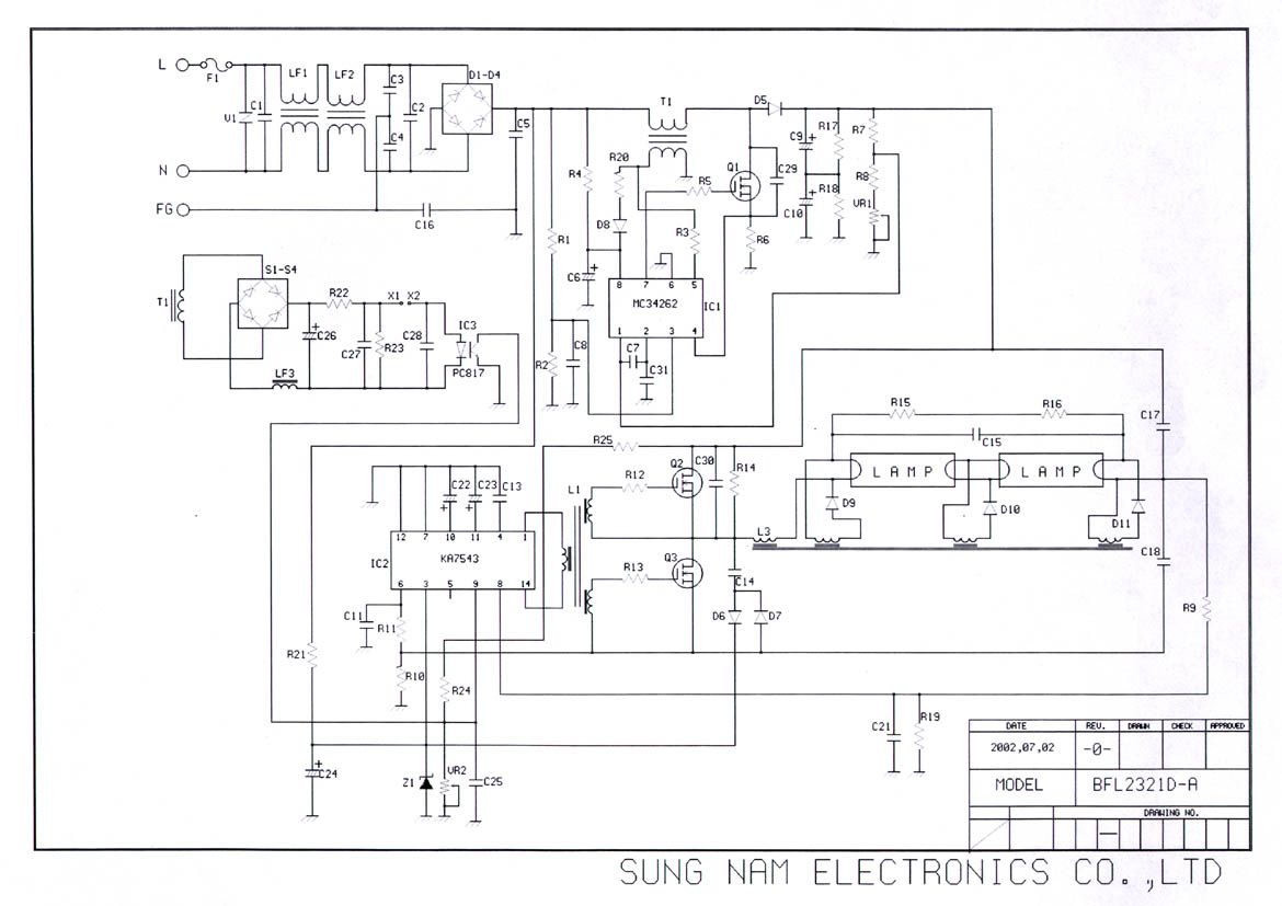
- Ballast
- Frequency Range
- 0.14000000 - 0.14000000
- Country
- South Korea
Documents & Files
Document Text
Text extracted from the exhibit documents filed with the FCC. Open a document above to read the original.
Users Manual
±± –
Test Report
KTL Korea Testing Laboratory Page 1 of 11 TEST REPORT This test report only responds to the tested sample and shall not be reproduced except in full without written approval of the Korea Testing Laboratory. Tested and reported by Reviewed by Jeong-Min Kim , Senior Engineer Hee-Soo Kim , Telecommunication Team Manager KOREA TESTING LABORATORY FG101-01-02-00 222-13, Guro-Dong Guro-Gu Seoul Korea 152-053 http://www.ktl.re.kr Ref. Report No. 02-341-022 Name and address of the applicant Sungnam Electronics Co., Ltd. 146-8, Sandaewon-dong, Joongwon-gu, Sungnam-shi, Kyounggi-do, 462-807, Korea Standard / Test regulation FCC Part 18 Test result Pass Incoming date : July 25, 2002 Test item(s) ; RF Lighting Devices – Consumer Equipment (Electronic Ballast) Model/type ref. ; BFL2321D-A Manufacturer ; Sungnam Electronics Co., Ltd. Additional information ; -Required Authorization : Certification -FCC ID. : QJPBFL2321D-A Test date : December 04, 2002 Issue date : December 16, 2002 Ref. Report No. 02 - 341 – 022 Page 2 of 11 Korea Testing Laboratory Telecommunication Team 222-13, Guro3-dong, Guro-gu, Seoul Korea 152-848 TABLE OF CONTENTS I. GENERAL INFORMATION 3 1. Grantee’s Name and Mailing Address 2. Manufacturer's Name and Mailing Address 3. Equipment Descriptions 4. Rules and Regulations 5. Measuring Procedure 6. Date of Measurement . CONDUCTED EMISSION MEASUREMENT (Section 18.307) 4 1. Test Procedure 2. Photograph for the test configuration 3. Sample Calculation 4. Measurement Data . RADIATED EMISSION MEASUREMENT (Section 18.305) 8 1. Test Procedure 2. Photograph for the test configuration 3. Sample Calculation 4. Measurement Data . TEST EQUIPMENTS USED FOR MEASUREMENT 11 Ref. Report No. 02 - 341 – 022 Page 3 of 11 Korea Testing Laboratory Telecommunication Team 222-13, Guro3-dong, Guro-gu, Seoul Korea 152-848 . GENERAL INFORMATION 1. Applicant’s Name and : Sungnam Electronics Co., Ltd. Mailing Address 146-8, Sangdaewon-dong, Joongwon-gu, Sungnam-shi, Kyounggi-do, 462-807, Korea 2. Manufacturer's Name and : Sungnam Electronics Co., Ltd. Mailing Address 146-8, Sangdaewon-dong, Joongwon-gu, Sungnam-shi, Kyounggi-do, 462-807, Korea 3. Equipment Descriptions 3.1 Input Voltage : AC 110 V, 60 Hz 3.2 Oscillation Frequency : 140 kHz 3.3 Lamp Wattage : 64 W 4. Rules and Regulations : FCC Part 18 5. Measuring Procedure : FCC / OET MP-5 (1986) 6. Date of Measurement 6.1 Conducted Emission : December 04, 2002 6.2 Radiated Emission : December 04, 2002 Ref. Report No. 02 - 341 – 022 Page 4 of 11 Korea Testing Laboratory Telecommunication Team 222-13, Guro3-dong, Guro-gu, Seoul Korea 152-848 . CONDUCTED EMISSION MEASUREMENT (Section 18.307) 1. Test Procedure The EUT was installed with fluorescent lamp in accordance with the manufacturer’s instruction and operated in a manner that is the representative of the typical usage for equipment. Conducted emission measurements on the EUT were performed by "Conducted Powerline Measurement" procedure as per MP-5. The EUT was set up on a wooden table 0.8 meters height, 1.0 by 1.5 meters in size, placed in the shielded enclosed with a side of wall of which constituted a vertical conducting surface of 2.2 m x 3.1 m in size to maintain 0.4 meters from the rear of EUT LISN's(Line Impedance Stabilization Network, EMCO, 3825/2, 50 ohm / 50 μH) were installed and electrically boned to the conducting ground plane. The EUT was connected to the LISN. One of two 50 ohm output terminals of the LISN was connected to the EMI Receiver(ROHDE & SCHWARZ, ESI7, 20 Hz to 7 GHz) and the other was terminated in 50 ohms. Measurements were again performed after interchanging such a connection oppositely. The frequency range from 150 kHz to 30 MHz was examined and the remarkable frequencies were measured with Quasi-peak and Average values using the EMI receiver instrument (ROHDE & SCHWARZ, ESI7, 20 Hz to 7 GHz ; Detector Function ; CISPR Quasi-Peak & Average). The 6 dB bandwidth of the Receiver was set to 9 kHz The position of connecting cables of the EUT was changed to find the worst case configuration during measurements. The maximum emission level from the EUT occurred in such configuration as shown in the following photograph. Ref. Report No. 02 - 341 – 022 Page 5 of 11 Korea Testing Laboratory Telecommunication Team 222-13, Guro3-dong, Guro-gu, Seoul Korea 152-848 2. Photograph for the test configuration 3. Sample Calculation The emission level measured in decibels above one microvolt (dB ) was converted into microvolt ( ) as shown in following sample calculation. For example : Measured Value at 12.13 MHz 56.9 dB @ QP-mode + Cable Losses * 0.0 dB ---------------------------------------------------------------------- = Conducted Emission 56.9 dB ( = 699.8 ) * In case of RG214/ RF cable 15 Ft, the loss is about 0.17 dB at the frequency of 30 MHz which is negligible. Ref. Report No. 02 - 341 – 022 Page 6 of 11 Korea Testing Laboratory Telecommunication Team 222-13, Guro3-dong, Guro-gu, Seoul Korea 152-848 4. Measurement Data - Resolution Bandwidth : x CISPR Quasi-Peak (6dB Bandwidth : 9 kHz) x Average (6dB Bandwidth : 9 kHz) Emission Level Limit (*) Mar gin Power Lead Tested Frequency (MHz) Q-Peak (dB ) Average (dB ) Q-Peak (dB ) Average (dB ) Q-Peak (dB ) Average (dB ) 0.150 47.8 36.1 66.0 56.0 - 18.2 - 19.9 0.180 45.1 31.5 64.5 54.5 - 19.4 - 23.0 10.770 56.8 46.5 60.0 50.0 - 3.2 - 3.5 12.130 56.9 46.5 60.0 50.0 - 3.1 - 3.5 19.170 48.4 42.4 60.0 50.0 - 11.6 - 7.6 - - - - - - - Live to Ground 0.150 46.3 36.7 66.0 56.0 - 19.7 - 19.3 0.170 44.4 31.6 65.0 55.0 - 20.6 - 23.4 10.680 54.4 46.1 60.0 50.0 - 5.6 - 3.9 12.050 56.5 46.2 60.0 50.0 - 3.5 - 3.8 18.460 49.1 42.4 60.0 50.0 - 10.9 - 7.6 - - - - - - - Neutral to Ground Note : Refer to measured graphs on next page. * Margin(dB) : Emission Level (dB) - Limit (dB) Ref. Report No. 02 - 341 – 022 Page 7 of 11 Korea Testing Laboratory Telecommunication Team 222-13, Guro3-dong, Guro-gu, Seoul Korea 152-848 (Test mode : Live to Ground) (Test mod…
Text truncated - open the document above for the full version.
Test Setup Photos
Ref. Report No. 02 - 341 – 022 Page 6 of 11 Korea Testing Laboratory Telecommunication Team 222-13, Guro3-dong, Guro-gu, Seoul Korea 152-848 2. Photograph for the test configuration 3. Sample Calculation The emission level measured in decibels above one microvolt (dB) was converted into microvolt () as shown in following sample calculation. For example : Measured Value at 12.13 MHz 56.9 dB + Cable Losses * 0.0 dB = Conducted Emission 56.9 dB ( = 699.8 ) * In case of RG214/RF cable 15 Ft, the loss is about 0.17 dB at the frequency of 30 MHz which is negligible. Ref. Report No. 02 - 341 – 022 Page 10 of 11 Korea Testing Laboratory Telecommunication Team 222-13, Guro3-dong, Guro-gu, Seoul Korea 152-848 2. Photograph for the test configuration 3. Sample Calculation The emission level measured in decibels above one microvolt (dB) was converted into microvolt per meter (/m) as shown in following sample calculation. For example : Measured Value at 30.9 MHz 17.2 dB + Antenna Factor 18.5 dB + Cable Loss 1.0 dB - Preamplifier 0.0 dB - Distance Correction Factor * 20.0 dB -------------------------------------------------------------------------------- = Radiated Emission 16.7 dB/m ( = 6.8 /m ) * Extrapolated from the measured distance to the specified distance by an inverse linear distance extrapolation.
Contact Information
Applicant
Chan Rok Park(Manager)
Test Firm
Korea Testing LaboratoryJeong-Min Kim
Technical Specifications
| # | Rule Parts | Frequency Range | Power Output |
|---|---|---|---|
| 1 | 18 | 0.14 MHz - 0.14 MHz | - |