Text extracted from the exhibit documents filed with the FCC. Open a document above to read the original.
PAT America Motion Alert Instruction Manual Description The Pat Motion Alert System is intended to provide a machine operator with the ability to warn personnel within range of a moving load when motion is imminent calling attention to the dangerous, silent moving load. Attached to the load, the Motion Alert’s Beacon is controlled wirelessly by the equipment operator. The system consists of the Beacon, typically attached to a crane hook block or to the actual moving load, and a remote Control Unit that activates the Beacon’s alarm and sets the signal mode – audio, visual or both. The system allows a crane operator to signal riggers when the crane hook and load is going to start moving, or a fork truck driver with a large load obstructing his view to warn personnel that a load is coming their way. Installation Instructions Beacon: The Beacon is attached to the load with the supplied carabineer or nylon strap or by hardware supplied by the user. It is critical that the Beacon is attached suitably to avoid accidental detachment allowing the Beacon to possibly injure personnel. The beacon can be attached either to the machine, a crane hook block or directly to a load. In situations where large loads are being moved such as steel beams, one beacon may be attached to each end and set to trigger from the same Control Unit. Control Unit: There are two versions of the Control Unit, a battery powered portable unit and a vehicle-powered unit run off a vehicle’s power system. Either unit can be permanently mounted. The Control Unit is mounted in the machine cab with the alarm button convenient to the operator using the supplied velcro strips or with optional mounting brackets and hardware. The vehicle-powered unit is wired as shown in the table. (Input Voltage 9-30VDC) In the vehicle-powered unit, up to four machine signals can be connected to cause the Beacon to alarm automatically. The inputs must be continuous signals, 5VDC up to the input voltage. Each signal is separated by a diode, so the input signals are isolated from one another. To enable the automatic feature, connect the disable wire (yellow) to common (black.) If the automatic function is not used, disable it by connecting the disable wire (yellow) to the power wire(red.) The unit is shipped in this disabled configuration. Optional Pendant Switch A pendant switch can be used with either Control Unit to remotely position the alarm button for the operator’s convenience, such as attaching it to a joystick or a crane control pendant. For use with the portable Control Unit, plug the pendant into the receptacle at the bottom of the Control Unit. For use with the vehicle-powered unit, cut the plug off the pendant and attach the two wires across the pendant (white) and common (black) leads of the multi conductor cable. Instructions for Use Beacon: Attach the Beacon to the crane hook, the load being moved or to the machine in the area of personnel danger. It is critical that the Beacon is attached suitably to avoid accidental detachment allowing the Beacon to possibly injure personnel. For the best communication between the Beacon and the Control Unit, try to place the Beacon on the side of the load nearest the Control Unit position. Control Unit: The Control Unit sets the alarm mode and triggers the Beacon. Pressing the Select Mode button scrolls through the options for visible alarm, audible alarm or both. If the unit is wired into the machine for automatic alarm, the auto alarm option can also be selected when scrolling. The Alarm On/Off button on the Control Unit turns the Beacon on or off. Pressing once causes the Beacon to alarm. Pressing the button again will turn off the Beacon. The LED on the Control Unit indicates the status of the Beacon. In automatic mode, signals from the machine automatically trigger the alarm while these functions are in use. In automatic mode, the Alarm On/Off button will still turn on the Beacon, but it cannot turn off the Beacon that is being activated automatically. The LEDs on the vehicly-powered unit are on continuously, and on the portable Control Unit they stay on momentarily. Wire Color Function Black Common White Pendant Red Power Green Auto In 1 Brown Auto In 2 Blue Auto In 3 Orange Auto In 4 Yellow Auto Disable PAT America, Inc. 1665 Orchard Dr Chambersburg, PA 17201 (717) 263-7655 Replacing the Batteries Control Unit: Remove 4 screws that hold back and front of unit together. Once open, replace 9V battery. Beacon: Remove the three screws holding the end of the unit with the light and alarm to the yellow case. Slide the assembly out and replace the three D cells. This also provides access to the learn switch required for teaching the Beacon a new address. (see below) Setting Address for Motion Alert Systems Used in the Same Area The Motion Alert system allows you to set the Beacon to respond to any Control Unit. As shipped, the Control Unit and Beacon are addressed to work together. It is possible that you may have received multiple units with the same address so that one Beacon goes off unintentionally when another is activated. The system can be set up so that each Control Unit operates a single Beacon independently, or so that one Control Unit operates multiple Beacons (to have a beacon on each end of a long beam) or so one Beacon is operated by multiple Control Units (such as a vehicle-powered Control Unit in a cab and a portable Control Unit in use by an observer.) Setting the System Address To set the address of the Control Unit and beacon, you first set the Control Unit address. The Control Unit then teaches one or multiple Beacons this address. To change the Control Unit address and place it into teach mode, press and hold the Select Mode and Alarm On/Off buttons for 5 sec until the alarm led starts flashing. The Control Unit is now in teach mode and can be readdressed, if necessary. The visual alarm mode LED blinks from 1-8 times to indicate the current address. To change address, press Select…
Text truncated - open the document above for the full version.
Date: September 20, 2002 To: Federal Communications Commission From: Ted Graef Intuitive Control Systems, LLC 204 Calder Way Suite 208 State College, PA 16801 (814) 235 7790 [email protected] Subject: Cover Letter for Form 731 Submission EA691994 In this application, we are seeking approval for the Pat Motion Alert Transmitters under Section 15.249. The Motion Alert Beacon is an alarm that gets placed on a moving load, typically a crane. An operator uses a wireless Control Unit transmitter to activate the Beacon remotely, either with the standard unit that is powered by the machine, or with a battery powered portable transmitter. The system is based on the Linx ES series RF Modules. Sheet two of this letter has more information on the product. In form 731, the wrong classification may have been selected. It was submitted under DXT –Part 15: Low power transceiver, Rx verified, but the control unit is only a transmitter. The correct classification may be the DXX classification for a Low power communication device transmitter. Please call me if I can provide any additional information. Thank you. Motion Alert Product Description: The Motion Alert protects personnel and loads. The brightly colored, loud, flashing beacon is attached to a moving load on a crane or other load-moving equipment. This beacon is wirelessly controlled by the equipment operator, who can then draw attention to the actual danger – the otherwise silent, moving load. The alarm signal is 8¼” long and weighs less than 3 pounds. Its case is designed with multiple fastening points for carabineer clips or nylon straps, allowing easy on/easy off and ensuring the beacon gets used consistently. Features and Benefits of the Motion Alert Feature: Motion Alert beacon is attached to the moving load Benefit: Attention is drawn to the location of the potential hazard Feature: Operator controlled via wireless controller Benefit: Allows operator to trigger alarm with the touch of a button before or during load movement, alerting personnel near the load without distracting the operator from equipment operation. Feature: Flexible mounting options via numerous fastening points on beacon Benefit: The Motion Alert beacon is quickly and easily attached/detached from moving loads using common attachments such as carabineers or nylon straps. Feature: Operator can select visual and/or audible alarm for Motion Alert beacon Benefit: The alert can be tailored to different situations. Feature: Both the Motion Alert beacon and controller use standard batteries Benefit: Lasting 1-3 months depending on use, these battery powered models are ready to use out of the box and require no additional recharging hardware or external wiring.
Date: September 20, 2002 To: Federal Communications Commission From: Ted Graef Intuitive Control Systems, LLC 204 Calder Way Suite 208 State College, PA 16801 (814) 235 7790 [email protected] Subject: Confidentiality of Schematics for Form 731 EA691994 Please keep the schematics attached to Form 731 EA691994 confidential. The schematic is proprietary to Intuitive Control Systems, LLC and should not be available in the public domain. Thank you, Ted Graef President
Motion Alert Battery Powered Portable Control Unit Intuitive Control Systems, 9/20/02 FCC QJRMA Page 1 of 2 PAT Motion Alert Control Unit , Part Number 4000065 Input Voltage: 9 VDC, (Duracell MN 1604 or equiv.) To place Control Unit into teach mode or change address: Press and hold mode and alarm buttons for 5 sec until alarm led starts flashing. Unit now in teach mode. Press mode button to change address, if desired. Press alarm button or wait 2 min to automatically return to operating mode. To teach Beacon Control Unit address: With Control Unit in teach mode, open signal unit and press learn button for 2 sec. 1 beep indicates learn mode, 3 beeps indicates address learned. 5 beeps indicate an error - repeat process. FCC ID USA QJRMA This device complies with part 15 of the FCC Rules. Operation is subject to the following two conditions: (1) This device may not cause harmful interference, and (2) this device must accept any interference received, including interference that may cause undesired operation. PAT America, Inc. 1665 Orchard Dr Chambersburg, PA 17201 (717) 263-7655 Motion Alert Battery Powered Portable Control Unit Intuitive Control Systems, 9/20/02 FCC QJRMA Page 2 of 2
Motion Alert Standard Portable Control Unit Intuitive Control Systems, 9/20/02 FCC QJRMA Page 1 of 2 PAT Motion Alert Control Unit , Part Number 4000060 Input Voltage: 9-30 VDC To place Control Unit into teach mode or change address: Press and hold mode and alarm buttons for 5 sec until alarm led starts flashing. Unit now in teach mode. Press mode button to change address, if desired. Press alarm button or wait 2 min to automatically return to operating mode. To teach Beacon Control Unit address: With Control Unit in teach mode, open signal unit and press learn button for 2 sec. 1 beep indicates learn mode, 3 beeps indicates address learned. 5 beeps indicate an error - repeat process. FCC ID USA QJRMA This device complies with part 15 of the FCC Rules. Operation is subject to the following two conditions: (1) This device may not cause harmful interference, and (2) this device must accept any interference received, including interference that may cause undesired operation. PAT America, Inc. 1665 Orchard Dr Chambersburg, PA 17201 (717) 263-7655 Motion Alert Standard Portable Control Unit Intuitive Control Systems, 9/20/02 FCC QJRMA Page 2 of 2
Motion Alert Beacon Intuitive Control Systems, 9/20/02 FCC QJRMA Page 1 of 3 Motion Alert Beacon Intuitive Control Systems, 9/20/02 FCC QJRMA Page 2 of 3 Motion Alert Beacon Intuitive Control Systems, 9/20/02 FCC QJRMA Page 3 of 3 PAT Motion Alert Beacon, Part Number 4000059 Input Voltage: 4.5 VDC, 3 D Cells (Duracell MN1300 or equiv.) To teach Beacon Control Unit address: With Control Unit in teach mode, open signal unit and press learn button for 2 sec. 1 beep indicates learn mode, 3 beeps indicates address learned. 5 beeps indicate an error - repeat process. FCC ID USA QJRMA This device complies with part 15 of the FCC Rules. Operation is subject to the following two conditions: (1) This device may not cause harmful interference, and (2) this device must accept any interference received, including interference that may cause undesired operation. Battery Polarity: PAT America, Inc. 1665 Orchard Dr Chambersburg, PA 17201 (717) 263-7655 Motion Alert, Model MA SN# 400006540020101 US PAT # XXXXXX Open other end for battery replacement PAT America, Inc. 1665 Orchard Dr Chambersburg, PA 17201 (717) 263-7655
Correspondence Reference Number: 24018 731 Confirmation Number: EA691994 Revised Labels for Pat Motion Alert, with USA removed between FCC ID and QJRMA FCC QJRMA Ted Graef Intuitive Control Systems 10/1/02 PAT Motion Alert Control Unit , Part Number 4000065 Input Voltage: 9 VDC, (Duracell MN 1604 or equiv.) To place Control Unit into teach mode or change address: Press and hold mode and alarm buttons for 5 sec until alarm led starts flashing. Unit now in teach mode. Press mode button to change address, if desired. Press alarm button or wait 2 min to automatically return to operating mode. To teach Beacon Control Unit address: With Control Unit in teach mode, open signal unit and press learn button for 2 sec. 1 beep indicates learn mode, 3 beeps indicates address learned. 5 beeps indicate an error - repeat process. FCC ID QJRMA This device complies with part 15 of the FCC Rules. Operation is subject to the following two conditions: (1) This device may not cause harmful interference, and (2) this device must accept any interference received, including interference that may cause undesired operation. PAT America, Inc. 1665 Orchard Dr Chambersburg, PA 17201 (717) 263-7655 PAT Motion Alert Beacon, Part Number 4000059 Input Voltage: 4.5 VDC, 3 D Cells (Duracell MN1300 or equiv.) To teach Beacon Control Unit address: With Control Unit in teach mode, open signal unit and press learn button for 2 sec. 1 beep indicates learn mode, 3 beeps indicates address learned. 5 beeps indicate an error - repeat process. FCC ID QJRMA This device complies with part 15 of the FCC Rules. Operation is subject to the following two conditions: (1) This device may not cause harmful interference, and (2) this device must accept any interference received, including interference that may cause undesired operation. Battery Polarity: PAT America, Inc. 1665 Orchard Dr Chambersburg, PA 17201 (717) 263-7655 PAT Motion Alert Control Unit , Part Number 4000060 Input Voltage: 9-30 VDC To place Control Unit into teach mode or change address: Press and hold mode and alarm buttons for 5 sec until alarm led starts flashing. Unit now in teach mode. Press mode button to change address, if desired. Press alarm button or wait 2 min to automatically return to operating mode. To teach Beacon Control Unit address: With Control Unit in teach mode, open signal unit and press learn button for 2 sec. 1 beep indicates learn mode, 3 beeps indicates address learned. 5 beeps indicate an error - repeat process. FCC ID QJRMA This device complies with part 15 of the FCC Rules. Operation is subject to the following two conditions: (1) This device may not cause harmful interference, and (2) this device must accept any interference received, including interference that may cause undesired operation. PAT America, Inc. 1665 Orchard Dr Chambersburg, PA 17201 (717) 263-7655
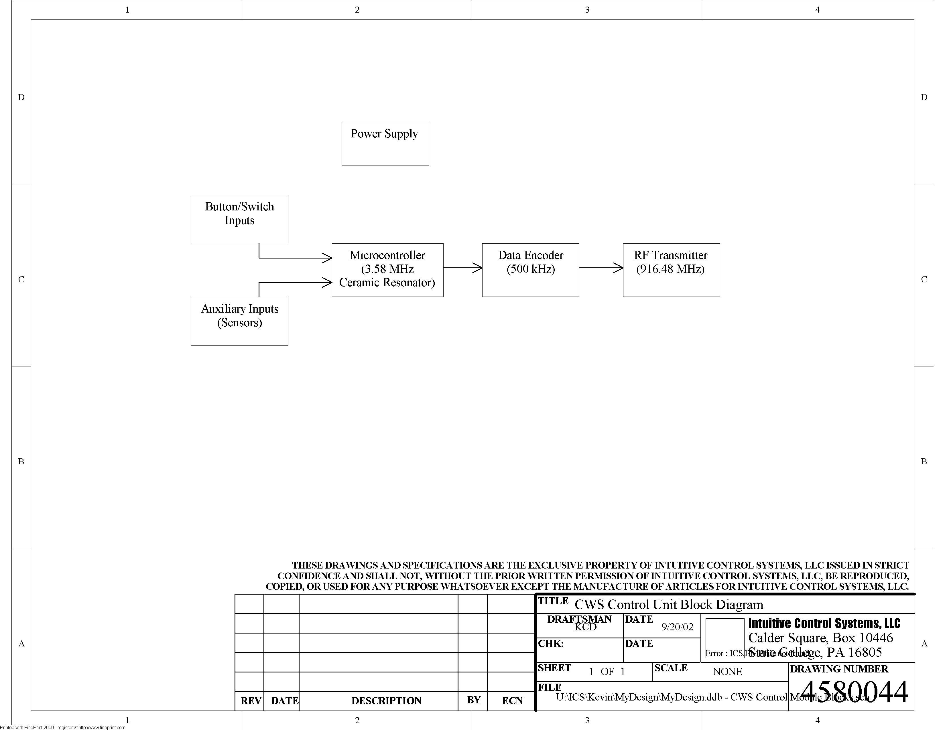
Motion Alert System Intuitive Control Systems, 9/20/02 FCC QJRMA Form 731 EA691994 Operational Description The transmitter unit come in two varieties: 1. A ‘standard’ unit which gets its power externally from the system (9V-30V) and can accommodate up to 4 auxiliary inputs to turn the alarm on and off automatically bypassing the Alarm switch 2. A portable ‘battery’ unit which is powered from a 9V battery and does not have any auxiliary inputs (the alarm must be turned on and off manually). Each transmitter unit can be broken up into four main blocks or functions: 1. Microcontroller 2. Data encoder 3. RF transmitter 4. Power regulator The microcontroller is the brains of the unit and determines the appropriate action to take based on various input conditions. The microcontroller uses a 3.58 MHz ceramic resonator for its clock. A user can select using the Mode button three possible alarm settings for the receiver (flashing lights, buzzer, or both). Using the Alarm button or external switch the user can turn the alarm on and off. (as mentioned above the standard unit also has 4 auxiliary inputs to turn the alarm on and off). Based on these inputs and conditions the microcontroller transmits one nibble (½ byte) of information to the encoder (the data is transmitted in parallel from the microcontroller to the encoder, no serial transmission occurs here). The encoder takes the data from the microcontroller and encodes it into several packets or bytes of information which is then sent to the RF transmitter module at a serial rate of 500 KHz. The encoder adds address information and start and stop bytes to the data to help prevent data corruption. The RF transmitter module transmits the encoded data to the receiver unit at a constant frequency of 916.48 MHz. No frequency hopping or spread spectrum techniques are used. The standard unit (the unit which is powered externally and has auxiliary inputs) uses a ½-wave whip antenna for its transmission while the portable battery unit (powered by a 9V battery, no auxiliary inputs) uses a ¼-wave whip antenna. The receiver unit also uses a ¼-wave whip antenna. The system is powered using a DC source which is then regulated to +5V (standard unit) or +3.3V (battery unit) using a linear regulator.
Radiation Sciences Inc. TEST REPORT NO. RSI-2367E ELECTROMAGNETIC INTERFERENCE (EMI) OF THE INTUITIVE CONTROL SYSTEMS PAT MOTION ALERT SYSTEM FCC PART 15, SUBPART C SECTION 15.249 3 SEPTEMBER 2002 PREPARED FOR: Intuitive Control Systems P.O. Box 10446 Suite 208 204 E. Calder Way State College, PA 16801 SUBMITTED BY: Radiation Sciences Inc. 3131 Detwiler Road Harleysville, PA 19438 PREPARED BY: ______________________ Jason Smith Lab Manager Test Engineer Radiation Sciences Inc. REVIEWED BY: ______________________ Jason Signore Technical Writer Radiation Sciences Inc. RSI-2367E ii Radiation Sciences Inc. TABLE OF CONTENTS SECTION TITLE PAGE Table of Contents i List of Figures i Administrative Data ii Summary of Test Results iii 1.0 INTRODUCTION 1 2.0 DESCRIPTION OF THE TEST SAMPLE 2 3.0 TEST INSTRUMENTATION 3 4.0 TEST RESULTS 4 4.1 Radiated Emissions (FCC Part 15 Section 15.249) 4 5.0 CONCLUSIONS 14 APPENDIX A RSI's Open Area Test Site ---- LIST OF FIGURES FIGURE 1 Radiated Test Setup Diagram 5 FIGURES 2, 3 Radiated Test Setup Photographs 6/7 FIGURES 4-9 RE for Intentional Radiators Data Sheets 8-13 RSI-2367E iii Radiation Sciences Inc. ADMINISTRATIVE DATA TEST PERFORMED: Measurements of Radiated Emissions. PURPOSE OF TEST: To evaluate the ElectroMagnetic Interference (EMI) characteristics of the Equipment Under Test with respect to Subpart C of Part 15 of the Federal Communications Commission (FCC) Rules for Inten- tional Radiators. EQUIPMENT UNDER TEST (EUT): Model: PAT Motion Alert System CONTRACT: Purchase Order Number: PD8070201 TEST PERIOD: 14-21 August 2002 TEST FACILITY: Radiation Sciences Incorporated (RSI), EMI/EMC Test Laboratory, located at: 3131 Detwiler Road, Harleysville Pennsylvania 19438. TEST PERSONNEL AND COORDINATORS: Radiation Sciences Inc. Intuitive Control Systems Ron Smith Ted Graef C. Kosiorek J. Smith RSI-2367E iv Radiation Sciences Inc. SUMMARY OF TEST RESULTS The PAT Motion Alert System manufactured by Intuitive Control Systems, configured as described herein, FULLY COMPLIES WITH THE REQUIREMENTS SET FORTH IN SUBPART C OF PART 15 OF THE FEDERAL COMMUNICATIONS COMMISSION (FCC) RULES FOR INTENTIONAL RADIATORS. The test results contained in this report represent emission and/or immunity characteristics of only the product (model and serial no.) tested. Radiation Sciences Inc. makes no claim that the test results contained herein will be obtained for a same model/equipment. RSI-2367E 1 Radiation Sciences Inc. 1.0 INTRODUCTION This document is a report of tests to determine the ElectroMagnetic Interference (EMI) characteristics of the PAT Motion Alert Systems presented by Intuitive Control System of State College, Pennsylvania. The purpose of the testing was to evaluate the EMI characteristics of the test sample with respect to Subpart C of Part 15 of the FCC Rules for Intentional Radiators. Test setups and procedures are described in RSI's Test Procedures 2059E/2 (see Appendix A) and test results are summarized herein on graphs. All test procedures used meet the requirements of the American National Standards Institute Procedure C63.4: "Methods of Measurements of Radio-Noise Emissions from Low-Voltage Electrical and Electronic Equipment in the Range of 9kHz to 40GHz" dated 17 July 1992. RSI-2367E 2 Radiation Sciences Inc. 2.0 DESCRIPTION OF THE EQUIPMENT UNDER TEST (EUT) The PAT Motion Alert System, manufactured by Intuitive Control Systems of State College, Penn- sylvania, is a safety device system. The transmitter sends a 916.4MHz carrier signal to the receiver/alarm, which would typically be mounted on a crane. An audible beep and/or a flashing light warning is activated alerting workers in the area that the crane is in motion or use to aid in avoiding injuries and alerting to stay clear of the work area. Hereinafter, the PAT Motion Alert System will be referred to as the EUT (Equipment Under Test). RSI-2367E 3 Radiation Sciences Inc. 3.0 TEST INSTRUMENTATION RSI CAL INV Due # Description Manufacturer Model Serial# Date Cycle 31 SPEC ANALYZER ADVANTEST R3271 J003583 3/8/2003 12 75 ANTENNA TENSOR 4108 204 5/8/2003 12 80 ANTENNA Amp. Res. Assoc. AT1000 4094-025 5/1/2003 12 391 RECEIVER Rhode &Schwartz ESVP 861744/015 1/2/2003 12 503 CONTROLLER EMCO 2090 0001-1489 52 ANTENNA EMCO 3115 2425 1/13/2003 12 705 30 FT CABLE PASTERNACK BNC TO BNC N/A 5/22/2003 12 707 6 FT CABLE BLUE CABLE SMA TO SMA N/A 4/8/2003 12 CAL DUE DATE = BLANK FIELD Calibration is not required. This equipment is not used to obtain a final reading. EXAMPLE: Transmitting Antenna RSI-2367E 4 Radiation Sciences Inc. 4.0 TEST RESULTS 4.1 Radiated Emissions (FCC Part 15 Section 15.249) Radiated Emissions Testing was performed to the requirements of FCC Part 15 Subpart C Section 15.249 at the Radiation Sciences Inc. (RSI) Open Area Test Site (OATS) located at 3131 Detwiler Road in Harleysville, Pennsylvania. Prior to testing, the EUT was pre-scanned with a near-field probe and spectrum analyzer. The probe was moved over the entire surface and all cables of the EUT and any emitting frequencies were re- corded. The EUT was then placed on a non-conductive turntable 80cm above the ground plane. The appropriate receiving antenna was placed on an antenna mast. Radiated Emissions testing was performed at a 10- meter distance from the EUT. The complete frequency range of 30MHz to 1000MHz was scanned with a Rohde & Schwarz CISPR Compliant Receiver. All signals were maximized by rotating the EUT 360° and moving the antenna from 1 to 4 meters in height. The maximum Radiated Emissions for the unin- tentional frequencies were then recorded and compared to the limits of FCC Part 15 Section 15.209. For the intentional frequency the EUT was tested at a distance of 3 meters. The levels of the fundamen- tal frequency and harmonics of the fundamental were maximized and compared to FCC Part 15 Section 15.249 limits. At frequencies above 1GHz a spectrum analyzer was used to record peak emissions. The test setup diagram is sh…
Text truncated - open the document above for the full version.
Calder Square · State College, Pennsylvania · United States
| # | Rule Parts | Frequency Range | Power Output |
|---|---|---|---|
| 1 | 15C | 916.48 MHz - 916.48 MHz | - |