QK7FSM-100FREESWITCH Wireless Transmitter
Adaptivation, Inc.
Click to zoom
Application Details
- Equipment Class
- DSR - Part 15 Remote Control/Security Device Transceiver
- Date of Grant
- Oct 15, 2002
- Application Purpose
- Original Equipment
- Date of Application
- Oct 15, 2002
- Equipment Note
- FREESWITCH Wireless Transmitter
- Frequency Range
- 309.80000000 - 309.80000000
- Company
- Adaptivation, Inc.
- Country
- United States
Documents & Files
Document Text
Text extracted from the exhibit documents filed with the FCC. Open a document above to read the original.
Users Manual
1 FREESWITCH MAX INSTRUCTIONS Please Read This Manual Before Operating ADAPTIVATION I N C O R P O R A T E D 2225 W. 50th St., Suite 100 Sioux Falls, SD 57105 1-800-723-2783 The World at a Touch 2 Table of Contents INTRODUCTION......................................................... 3 FEATURES................................................................ 3 TERMINOLOGY......................................................... 4 M ODES OF CONTROL................................................ 5 THEORY OF OPERATION............................................. 6 K EYPAD DESCRIPTION............................................... 7 SETTING THE TIMER................................................. 9 DELAYED ACTIVATION............................................. 10 S INGLE APPLIANCE SET UP.................................... 10 MULTIPLE APPLIANCE SET UP................................. 11 S CANNING OPTIONS................................................ 12 M ULTIPLE APPLIANCE SETUP USING VISUAL SCAN.... 14 MULTIPLE APPLIANCE AUDITORY SCANNING............. 15 CONSIDERATIONS.................................................... 16 T ROUBLESHOOTING................................................. 17 OVERLAY TEMPLATE.............................................. 19 WARRANTY........................................................... 20 3 INTRODUCTION With your new Adaptivation FreeSwitch Max environmental control system you can operate most AC or battery powered devices. Because the FreeSwitch Max is wireless, you are not tied down by cords or limited to a particular area in the room. The range of the FreeSwitch Max is approximately 35 to 50 feet or more. The FreeSwitch Max can accommodate a wide range of users through its various activation options. The FreeSwitch Max can operate up to 4 appliances through direct selection using the on-board keypad or by activating an external switch. It is also capable of operating up to 8 appliances when in the scanning mode. It can accommo- date users who prefer either visual or auditory scanning. The various mode operations of the FreeSwitch Max, which include a momentary, latched, or timed option, allow you to match the needs of the user to the appliance they wish to operate. The uses of the FreeSwitch Max are limited only by your imagination and ingenuity. Adaptivation strives to offer our clients the highest quality products and support. Feel free to contact us at any time for assistance using your FreeSwitch. FEATURES • Independently activate up to four AC or battery powered appliances with direct selection and eight with scanning selection all at the same time. • On-board keypad for direct and scanning selection. - Keypad templates can be made using Boardmaker 4 from Mayer-Johnson • External jacks for direct and scanning selection using adaptive switches. • All eight channels are independently capable of momen- tary, latching, timed seconds or timed minutes activa- tion. • Easy to read LED bar graph lets you know exactly what the timer is set to for each channel using timing activa- tion. NO GUESSING. • Up to 16 FreeSwitch Max units can be used in an area at the same time, each capable of operating its own eight devices. • Visual scanning selection with 4 choices of scan speed. • Auditory scanning selection with 4 choices of scan speed. - High quality, recordable voice messages for each channel. - External speaker jack for use with headphones. - Volume control knob for auditory scanning. • Scan among 2, 3, 4, 5, 6, 7 or all 8 channels. • Automatic and Inverse scanning selection. • Delayed activation with choice of four delay lengths. • Wireless (radio frequency) operation using a battery powered transmitter optimizes safety. • Up to 100 foot range indoors. • Durable design resists damage due to dropping, throwing and other rough usage. • Compatible with Powerhouse X-10 or Radio Shack Appliance Modules. • Compatible with Adaptivation's wireless receiver for operating battery powered devices. 5 TERMINOLOGY RF RF stands for radio frequency. RF devices can transmit through walls unlike infrared (IR) which requires line of sight. LED LED’s (light emitting diode) are the small red lights on the FreeSwitch Max. Transceiver Module The Transceiver Module will allow most electrical or AC appliances to be activated. The FreeSwitch sends a RF to the transceiver module which then controls other appliance modules. Appliance Module Appliance Modules activate electrical appliances. They receive their signal from the transceiver module through the wiring in your house. Wireless Receiver A Wireless Receiver will allow the FreeSwitch to control most battery-operated devices. House Code The House Code is the frequency the FreeSwitch Max uses to transmit to either a transceiver module or a wireless receiver. The House Code must be set to the same letter on both devices. Using different House Codes can allow different individuals to operate their own devices without interfering with each other. 6 Unit Code This code allows one transceiver module to operate up to 16 other appliances. The unit code on the FreeSwitch refers to the numbers 1 through 8 on the keypad. MODES OF CONTROL Momentary selection : The appliance activates for as long as the input button is depressed. Latched selection : Press once and the appliance turns on. Press again and it turns off Timed seconds : Press once and the appliance turns on then automatically turns off anywhere from 1 to 60 seconds later. Timed minutes : Press once and the appliance turns on then automatically turns off anywhere from 1 to 60 minutes later. Off: If a channel is set to Off, it will not activate. If a channel is in the off mode, there is no LED indica- tor on. 7 THEORY OF OPERATION This section contains useful information on the operation of your FreeSwitch Max. The FreeSwitch Max activates AC appliances via transceiver and appliance modules. Diagram 1 helps illustrate a typical scenario. 1.) The FreeSwitch Max is activated by p…
Text truncated - open the document above for the full version.
Cover Letter(s)
Date:09/24/2002 American Telecommunications Certification Body, Inc. 6731 Whittier Ave. Suite C110 McLean, VA 22101 RE:Certification Please be advised that the following information is to be held confidential on behalf of Adaptivation, Inc.: • Schematics The application contains technical information which Adaptivation, Inc. deems to be trade secrets and proprietary. If made public, the information might be used to the disadvantage of Adaptivation, Inc. in the market place. Thank you for your attention to this matter. Jonathan Eckrich President Adaptivation, Inc.
Cover Letter(s)
September 19, 2002 American Telecommunications Certification Body, Inc. 6731 Whittier Ave. Suite C110 McLean, VA 22101 To Whom It May Concern: Please be advised that Adaptivation, Inc. authorizes NCEE to act on our behalf, until otherwise notified, for applications submitted to American Telecommunications Certification Body, Inc. (ATCB). We certify that we are not subject to denial of federal benefits, that includes FCC benefits, pursuant to Section 5301 of the Anti-Drug Abuse ACT of 1988, U.S.C. 862. Further, no party as defined in 47 CFR 1.2002(b), to the application is subject to denial of federal benefits. Regards, Jonathan S. Eckrich President Adaptivation, Inc.
Cover Letter(s)
American Telecommunications Certification Body Inc. 6731 Whittier Ave, McLean, VA 22101 October 7, 2002 RE: FCC ID: QK7FSM-100 Attention: I have a few comments on this Application. 1 No operational or technical description has been provided with the application. Please provide an operational description for the device. xx 2 The device uses a “Momentary Mode” that the manual describes as the appliance being on as long as the switch is pressed. 15.231 devices cannot operate in a continuous transmission mode. 15.231 devices are limited to non-periodic, non-continuous control code transmissions only. Thus, it would not appear likely that an appliance could be directly connected to this device. Consequently, please explain how this mode works and how it prevents rf transmission while the switch is depressed while still operating the appliance? The maximum allowable transmission time is one second. Please explain why this device should not be denied. xx 3 This device sends rf signals over the household wiring. A current carrier system whereby signals are received by conduction directly from connection to the electric power lines are considered unintentional radiators. As such this portion is subject to verification. However, the requirements of 15.207 (conducted emissions) and 15.209 (radiated emissions) must be met for these devices. You have provided no conducted emissions results. Please provide the necessary tests for this device. xx 4 15.231 states that transmission of the device cannot be for longer than one second. Your manual states that the ‘delayed’ mode can be activated by pressing the switch for more than one second. This is not acceptable for 15.231 devices. Please explain this mode in detail and explain why this device should not be denied since it exceeds the maximum 1 second transmit requirements. xx 5 Your manual description of scanning mode is unclear. Does the device transmit during this mode? If so, it is not possible to certify under 15.231. Please provide a detailed explanation as to why the device should not be denied because of this mode. xx Dennis Ward mailto:[email protected] The items indicated above must be submitted before processing can continue on the above referenced application. Failure to provide the requested information may result in application termination. Correspondence should be considered part of the permanent submission and may be viewed from the Internet after a Grant of Equipment Authorization is issued. Please do not respond to this correspondence using the email reply button. In order for your response to be processed expeditiously, you must submit your documents through the AmericanTCB.com website. Also, please note that partial responses increase processing time and should not be submitted. Any questions about the content of this correspondence should be directed to the sender.
Cover Letter(s)
Subject: RE: FW: FW: Qk7fh-me request for info Date: Mon, 14 Oct 2002 12:19:15 -0500 From: "Doug Kramer" <[email protected]> To: <[email protected]> CC: "Jonathan Eckrich" <[email protected]> Dennis, Yes the FSM-100 also operates in this manner, the exception being 4 switches instead of 1. -----Original Message----- From: Dennis Ward [mailto:[email protected]] Sent: Monday, October 14, 2002 12:02 PM To: Doug Kramer Subject: Re: FW: FW: Qk7fh-me request for info Thanks Doug Yes it helps. Also, please understand the while I understand that this Protocol is currently in many devices, each application MUST stand on its own merit. Consequently, questions like this need to be answered so if and when the FCC has questions about these devices they can get all the answers they need by reviewing the single application. Sorry to be so picky about this, but as I said, every application must stand on its own regardless of the technology. Does the FSM-100 also operate in in this manner? If so, a return email stating This would be sufficient to answer the same question about that device. Thanks Dennis Doug Kramer wrote: > Dennis, > Does this help on the 2 FCC applications for QK7? > > -----Original Message----- > From: JSE [mailto:[email protected]] > Sent: Monday, October 14, 2002 11:40 AM > To: Doug Kramer > Subject: Re: FW: Qk7fh-me request for info > > Doug, > > Below are my responses to the questions from ATCB. > > 1 - When in "Direct Mode," the RF transmitter does not continuously > transmit. When the switch is > pressed, it transmits a single command to turn ON the A/C appliance. When > the switch is released, another single command is sent that turns OFF the A/C appliance. This gives the effect of the user have some sort of continuous control of the A/C appliance. Of course, the appliance is not directly connected to the transmitting device. The appliance is plugged into a third-party receiver (already been through FCC approval) that actually supplies or removes power from the A/C appliance. This receiver accepts commands from the RF transmitter. > > 2 - The transmitter sends 32-bits of data each time it transmits a command. Each bit takes 1.1 milliseconds, for a total of 35.2 milliseconds. After sending a command, the transmitter goes into a software loop for about 1.5 seconds where no further transmissions are allowed. This also allows enough time for the command to be processed by the receiver(s). > > ********************************************************************** > *** This protocol used is standard X10 format. There are dozens of *** > *** FCC-approved X10-compatible designs, tens of millions of units.*** > ********************************************************************** > > 3 - Because of the X10 encoding protocol, there are always as many marks > sent as nulls, and the duty > cycle over any small portion of the transmission is 50%. This is independent > of which of the 256 > address codes is selected. I would not expect a given code to result is > improved or diminished > modulation as compared to any other code. > > I hope this helps. Best Regards, > > Jon Eckrich > Adaptivation, Inc. > > Doug Kramer wrote: > > > Holly, > > > > Could you see if someone there could address the first 2 comments on the > > attached document? I've copied Jon on this too. > > > > Thanks, > > Doug Kramer > > NCEE > > 4740 Discovery Drive > > Lincoln, NE 68521 > > Tel: 402-472-5880 > > Fax: 402-472-5881
External Photos
FSM-100 Photos (Freeswitch Max)
ID Label/Location Info
FSM-100 FCC Label Artwork (Freeswitch Max) The FCC Label is white lettering on black background printed on a polyester label using a laser printer. It is affixed to the back side of the FSM-100 with permanent adhesive. The material to which the label is affixed is smooth ABS plastic. FCC ID: QK7FSM-100 This device complies with part 15 of the FCC rules. Operation is subject to the following two conditions: (1) this device may not cause harmful interference and (2) this device must accept any interference that may cause undesired operation.
ID Label/Location Info
FSM-100 FCC Label Position (Freeswitch Max) The FCC Label is white lettering on black background printed on a polyester label using a laser printer. It is affixed to the back side of the FSM-100 with permanent adhesive. The material to which the label is affixed is smooth ABS plastic.
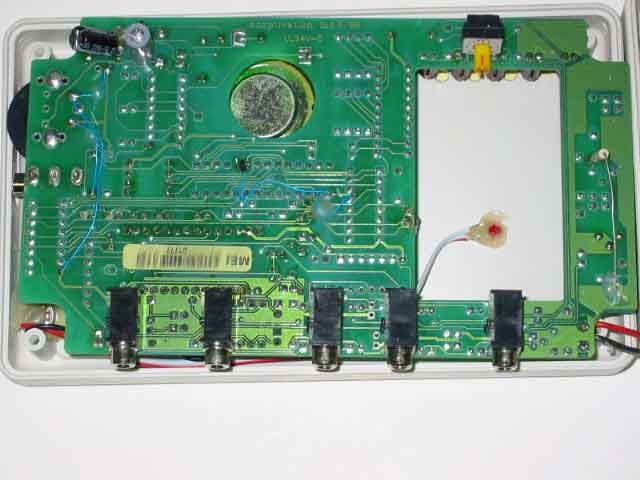
Internal Photos
FSM-100 Photos (Freeswitch Max)
Operational Description
FSM-100 Technical Description The Freeswitch Max (FSM-100) is a handheld, battery-powered RF transmitter. Its purpose is to allow users the ability to control AC appliances. The FSM-100 transmitted signal is 310-MHz, and is compatible with the prolific X10 protocol. The RF funtionality of the FSM-100 is virtually identical to X10 key chain transmitters available at numerous retail outlets (www.X10.com). The FSM-100 is physically much larger, though, to accommodate the needs of persons with disabilities. In addition, it allows the control of multiple A/C appliances. Typically, the FSM-100 is used to turn ON/OFF lamps, radios, stereos, etc. in classrooms and in special education settings. The dimensions of the ABS plastic enclosure are 3.75” x 6.25” x 1.8”. The FSM-100 consists of a PCB, through-hole electronics, and a 1/8-λ wire antenna. Following is a sample diagram showing a portion of the X10 RF protocol. The 310-MHz carrier is modulated by powering the RF oscillator ON/OFF. +--------+ +--------+ +--------+ +- | 9 msec | 4 msec | .55ms | .55ms | .55ms | .55ms 1.1ms | + +--------+ +--------+ +--------+---------------+ | preamble | logic 1 | logic 0 | Any given command transmitted by the FSM-100 sends four logical bytes to the X10 receiver including error detection, resulting in a total transmission length of 65.8 msec. The on-board microprocessor is held in sleep mode (clock oscillator disabled) until a switch is pressed, whereby the microprocessor is activated, and the clock oscillator runs at 32,7668 Hz. After the X10 command is transmitted, the microprocessor returns to sleep mode until the switch is pressed again. The X10 protocol allows up to 256 appliances to be uniquely addressed. The FSM-100 has a rotary switch that is used to set this address. The appliance plugged into the X10 receiver module that has the same address as the FSM-100 will respond to command signals sent given that the receiver and FSM-100 are in range.
Test Report
R081402-01-2 FCC ID: QK7FSM-100 NCEE NEBRASKA CENTER FOR EXCELLENCE IN ELECTRONICS 4740 Discovery Drive Lincoln, NE 68521 402-472-5880 Test Report Company: Adaptivation Inc. 2225 W 50 th Street, Suite 100 Sioux Falls, SD Contact: Jonathan Eckrich Product: FSM-100 FCC ID: QK7FSM-100 Test Report No: R081402-01-2 APPROVED BY: Steve Cass _________________________ General Manager Doug Kramer _________________________ Test Engineer DATE: 30 September 2002 Total Pages: 11 The Nebraska Center for Excellence in Electronics (NCEE) authorizes the above named company to reproduce this report provided it is reproduced in its entirety for use by the company’s employees only. Any use that a third party makes of this report, or any reliance on or decisions made based on it, are the responsibility of such third parties. NCEE accepts no responsibility for damages, if any, suffered by any third party as a result of decisions made or actions based on this report. This report applies only to the items tested. NCEE is a FCC registered lab. Registration #100875 NCEE R081402-01-2 FCC ID: QK7FSM-100 Page 2 of 11 Table of Contents 1.0 Summary of test results 1.1 Test Results 1.2 Test Methods 2.0 Description 2.1 Equipment under test 2.1.1 Identification 2.1.2 EUT received date 2.1.3 EUT tested date 2.1.4 Manufacturer 2.1.5 Serial number 2.2 Laboratory description 2.3 Special equipment or setup 3.0 Test equipment used 4.0 Detailed Results 4.1 FCC Part 15.203 Conducted Emissions 4.2 FCC Part 15.231 Radiated Emissions Appendix A – Test setup photos Appendix B – Emissions results Appendix C – Sample Calculation NCEE R081402-01-2 FCC ID: QK7FSM-100 Page 3 of 11 1.0 Summary of test results 1.1 Test Results The EUT was shown to comply with the guidelines for intentional radiators according to Parts 15.203, 15.209 and 15.231. See Section 4 for more detailed information. The unit is battery operated and does not connect to the mains network. 1.2 Test Methods The equipment was tested to comply with CFR 47, Part 15, for intentional radiators. The EUT was tested in accordance to methods of ANSI/IEEE C63.4, 2001. The configuration of the EUT was varied to maximize emissions. All measurements were made at a distance of 3 meters; the antenna height was varied from 1 meter to 4 meters. Both antenna polarizations were examined. The orientation of the EUT was first examined to determine in which position the EUT produced the greatest emissions. New 9V alkaline batteries were used. 2.0 Description 2.1 Equipment under test The FSM-100 is a battery-powered transmitter designed to work with Wireless Receivers or Powerhouse X-10 modules. The unit is intended to be used by persons unable to operate smaller buttons or reach standard switches. 2.1.1 Identification: FSM-100 2.1.2 EUT received date: 15 August 2002 2.1.3 EUT tested date: August 28 th and September 3 rd of 2002 2.1.4 Manufacturer: Adaptivation, Inc 2.1.5 Serial numbers: test1 2.2 Laboratory description All testing was performed at the NCEE Lincoln facility, which is a FCC registered lab. This site has been fully described in a report submitted to the FCC, and accepted in a letter dated May 4, 2001. Laboratory environmental conditions varied slightly throughout the tests: Relative humidity of 56 ± 5% Temperature of 24 ± 3° Celsius 2.3 Special equipment or setup The unit was modified so it would transmit continuously. NCEE R081402-01-2 FCC ID: QK7FSM-100 Page 4 of 11 3.0 Test equipment used Serial # Manufacturer Model Description Last cal. 1654 EMCO 3142B Biconilog antenna 3-May-02 6415 EMCO 3115 DRG Horn ant. 24-Oct-01 100037 Rohde & Schwarz ESIB26 EMI Test Receiver 11-Jun-02 2575 Rohde & Schwarz ES-K1 Software v1.60 N/A 4.0 Detailed Results 4.1 FCC Part 15.203 The antenna is soldered to the printed circuit board and there are no connectors attached to it or leading from the case. The plastic case is sealed. Thus the EUT complies with part 15.203. 4.2 FCC Part 15.231 The EUT, SN: test1, was used to first find the orientation of the EUT that provided the worst case. The emissions from the unit were then examined from 30MHz to 4GHz. The antenna was positioned 3m from the EUT and the antenna position was varied between 1 and 4 meters as the EUT was rotated on the turntable. Figures 1 and 2 show the test setup that provided a worst-case configuration; this configuration is also the orientation of typical use. The table below shows the final measurements. Frequency Level Limit Margin Height AnglePol. MHz dBμV/m dBμV/mdB cm deg 309.78 59.99 75 15.01100 195 HORIZONTAL 309.9 62.02 75 12.98100 200 HORIZONTAL 619.68 29.34 55 25.66100 262 VERTICAL 896.4 28.19 46 17.81304 160 HORIZONTAL 929.58 34.65 55 20.35149 274 HORIZONTAL 1548.16 35.6 53.9 18.3 349 192 HORIZONTAL 2830.66 43.22 53.9 10.68149 54 HORIZONTAL 3196.54 44.1 53.9 9.8 99 47 HORIZONTAL All final measurements were taken using a quasi-peak detector set to 120kHz bandwidth for measurements under 1GHz, for measurements over 1GHz an average detector set to 1MHz bandwidth was used. Appendix B contains a plot of the results from 30MHz to 1 GHz (Figure 3) and of the bandwidth (Figure 4) of the fundamental. The signal bandwidth as measured was 200kHz. All measurement results are located in the corresponding interval with a probability of approximately 95% (coverage factor k=2). The interval for these measurements is U x (expanded uncertainty) = +/- 3.4 dB. NCEE R081402-01-2 FCC ID: QK7FSM-100 Page 5 of 11 Appendix A Test setup photos NCEE R081402-01-2 FCC ID: QK7FSM-100 Page 6 of 11 Figure 1 Test setup Figure 2 Test setup NCEE R081402-01-2 FCC ID: QK7FSM-100 Page 7 of 11 Appendix B Emissions results NCEE R081402-01-2 FCC ID: QK7FSM-100 Page 8 of 11 0 10203040506070 Level [dBμV/m] 30M 40M 50M 70M 100M 200M 300M 400M 600M 1G Frequency [Hz] ++ + + + + + MES adp090302a_fin MES adp090302a_pre PK LIM FCC ClassB F QP/AV FCC ClassB, field strength 3m Page 1 9/3/2002 4:48PM Figure 3 Results of radiated emissions NCEE R081402-01-2 FCC ID: QK7FSM-1…
Text truncated - open the document above for the full version.
Test Setup Photos
NCEE R081402-01-2 FCC ID: QK7FSM-100 Page 6 of 11 Figure 1 Test setup Figure 2 Test setup
Contact Information
Applicant
Jonathan S Eckrich(President)
Technical Contact
Adaptivation,Jon Eckrich,
[email protected]605-335-4445
2225 W 50 St, Suite 100 · Sioux Falls, South Dakota · United States
Non-Technical Contact
Adaptivation,Holly Tull
[email protected]605-335-4445
Test Firm
Nebraska Center for Excellence in ElectronicsSteve Cass
Technical Specifications
| # | Rule Parts | Frequency Range | Power Output |
|---|---|---|---|
| 1 | 15.231 | 309.8 MHz - 309.8 MHz | - |
Other Applications from Adaptivation, Inc.

QK7FH-ME
Oct 15, 2002FreeHand wireless transmitter
Equipment Class
DSC - Part 15 Security/Remote Control Transmitter