QKFREMOTEASSMPendant Control
Tarus Products, Inc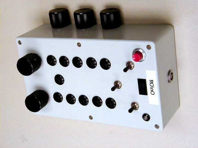
Click to zoom
Application Details
- Equipment Class
- DXT - Part 15 Low Power Transceiver, Rx Verified
- Date of Grant
- Aug 27, 2002
- Application Purpose
- Original Equipment
- Date of Application
- Aug 27, 2002
- Equipment Note
- Pendant Control
- Frequency Range
- 903.37000000 - 921.37000000
- Company
- Tarus Products, Inc
- Country
- United States
Documents & Files
Document Text
Text extracted from the exhibit documents filed with the FCC. Open a document above to read the original.
Users Manual
PENDANT CONTROL The PENDANT CONTROL (or remote pendant) is used to operate the machine away from the trackball station or keyboard. Manual machine movement (JOGGING), and CNC cutting (Cycle start and Abort) are performed from the remote pendant. The remote pendant consists of the following: 1) THREE JOG PADDLES (one for each axis) 2) TEN PUSH BUTTONS 3) FEED POTENTIOMETER (Feed pot) 4) SPINDLE R.P.M POTENTIOMETER (Spindle pot) When you first look at the remote pendant, you might be confused because none of the buttons are labeled. Don't get discouraged because the SCREEN is where all the button descriptions are given. Look at the graphic illustration of the pendant on screen to see what the buttons represent. JOGGING THE MACHINE The machine is always in the jog mode while the axis drives are on. The hand wheels are also active at this time. To make the machine move, push any one of the “jog paddles”. The feedrate can be adjusted using the “feed pot”. Below the pendant, there is the option to adjust the Maximum Jog Speed (feedrate). The feedrate can be set from 3% of maximum to 100%. Pick or highlight the percentage of maximum that you want the machine to move. JOG SPEED = 3% 25% 50% 100% The feedrate is infinitely variable UP TO the maximum jog speed with the feed pot. Pushing the jog paddles will make the machine move. It is best to start moving the machine around slowly until you have become familiar with how the machine accelerates and de-accelerates. JOG To JOG the machine the DRIVES must be ON. With the drives on, the prompt (ICON) in the lower right hand corner of the screen will indicate that the machine is in the JOG MODE. Simply move the jog paddle on the remote pendant (the axes are displayed for which paddle jogs which axis) and the machine will move. Turning the FEEDPOT (right hand pot on pendant) can infinitely vary the feedrate at which the machine jogs. The maximum feedrate is set to the system max feed. X Y Button #1 Button #3 Button #5 Button #7 Button #9 Button #2 Button #4 Button #6 Button #8 Button #10 Z Spindle pot Feed Pot JOG PADDLES REMOTE PENDANT The device that is attached to the graphics monitor is the hand held remote PENDANT. At this pendent, the operator has much flexibility to run the machine by not having to be right at the control to execute various functions. You can move around the machine freely with the pendant in hand. The on-screen-pendant menu indicates what each button on the pendant does, which is why the buttons on the pendant are not physically marked, because in different modes of operation, the buttons perform different tasks. In addition to the buttons, there are 3 jog paddles, and 2 pots (potentiometers). The top left paddle jogs X- axis, the top right jogs Y-axis and the lower middle one jogs Z as indicated on the menu. The left "pot" controls the spindle RPM'S. This “SPINDLE POT” allows you to vary the spindle speed from 0 to maximum RPM (the max RPM is set on the menu in “R.P.M”). To change Jog Modes from X Y Z jog, to A B Z jog, you press the [X Y Z] pendant button. This will toggle over to [A B Z], which means you can then jog the A and B-axis along with Z-axis. The right "pot" controls the feedrate or “feed override”. With the exception of a few commands in the software, the FEEDRATE is constantly adjustable by using the “FEED POT”. In EXECUTE or when running a CNC program the feedrate “MAX” will be determined by what is entered in FEEDRATE on the menu. The feedrate can be adjusted by using the FEED POT to go from minimum to maximum feed. EMERGENCY STOP There also is a RED button on top of the pendant. This is an EMERGENCY STOP. When this button is hit, the drives are shut off. There is also an "E-STOP" on the side of the graphics monitor. Normally when the machine is not in use, the drives should be turned off. FCC INFORMATION: Class A Device Statement: (Section 15.105(a) of the FCC Rules) Note: This equipment has been tested and found to comply with the limits for a Class A digital device, pursuant to part 15 of the FCC Rules. These limits are designed to provide reasonable protection against harmful interference when the equipment is operated in a commercial environment. This equipment generates, uses, and can radiate radio PrstY PrstX XYZ Rapid Spin Feed X Z Y PrstZ VecJog Cut frequency energy and, if not installed and used in accordance with the instruction manual, may cause harmful interference to radio communications. Operation of this equipment in a residential area is likely to cause harmful interference in which case the user will be required to correct the interference at his own expense.
External Photos
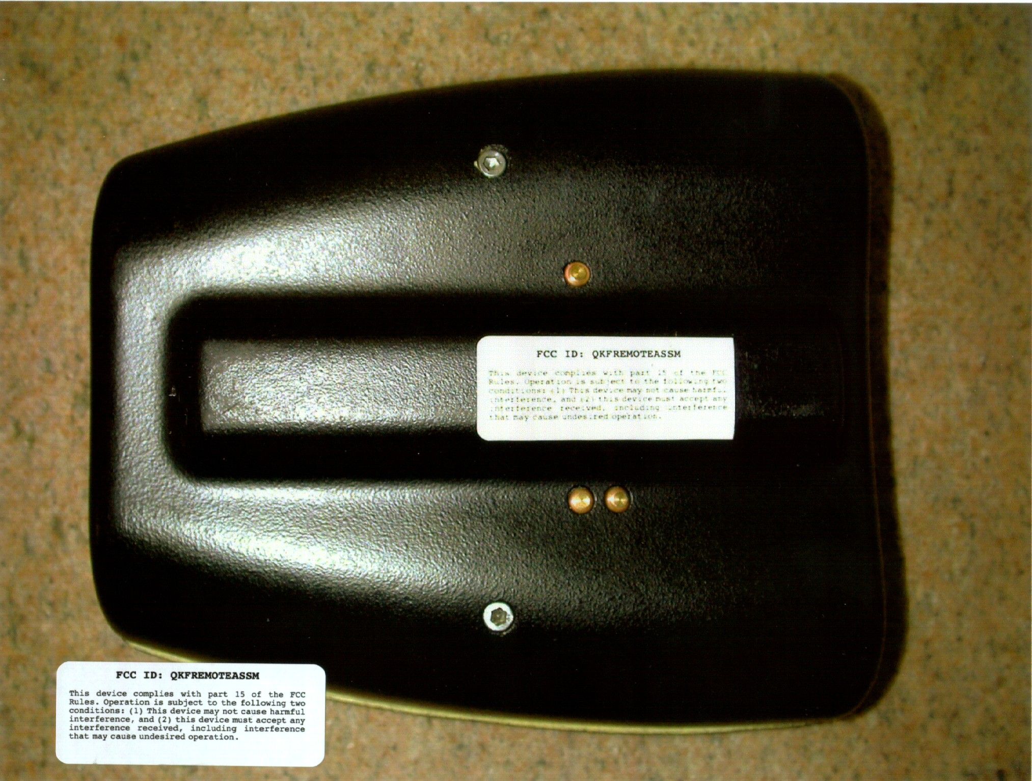
A FCC ID: QKFREMOTEASSMAugust 2002 Page 30 of 37 EXHIBIT IIIEXHIBIT III EXTERNAL PHOTOSEXTERNAL PHOTOS A FCC ID: QKFREMOTEASSMAugust 2002 Page 31 of 37 External Photo
Internal Photos
A FCC ID: QKFREMOTEASSMAugust 2002 Page 32 of 37 EXHIBIT IVEXHIBIT IV INTERNAL PHOTOSINTERNAL PHOTOS A FCC ID: QKFREMOTEASSMAugust 2002 Page 33 of 37 Internal Photo A FCC ID: QKFREMOTEASSMAugust 2002 Page 34 of 37 Internal Photo A FCC ID: QKFREMOTEASSMAugust 2002 Page 35 of 37 Internal Photo
Operational Description
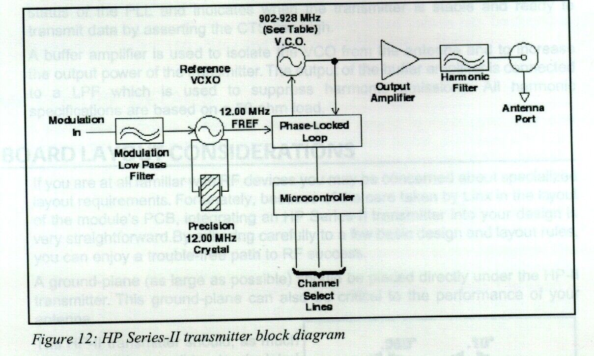
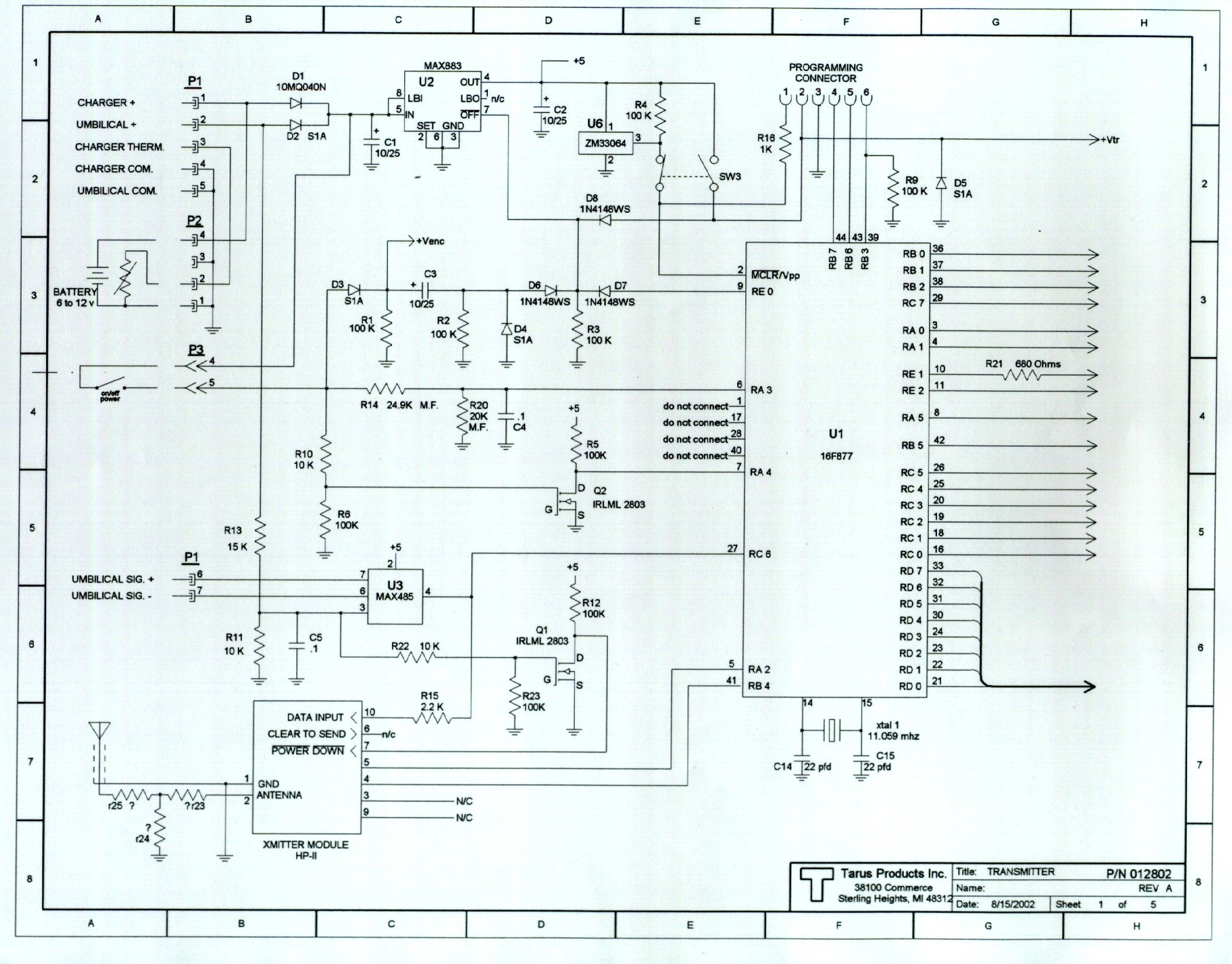
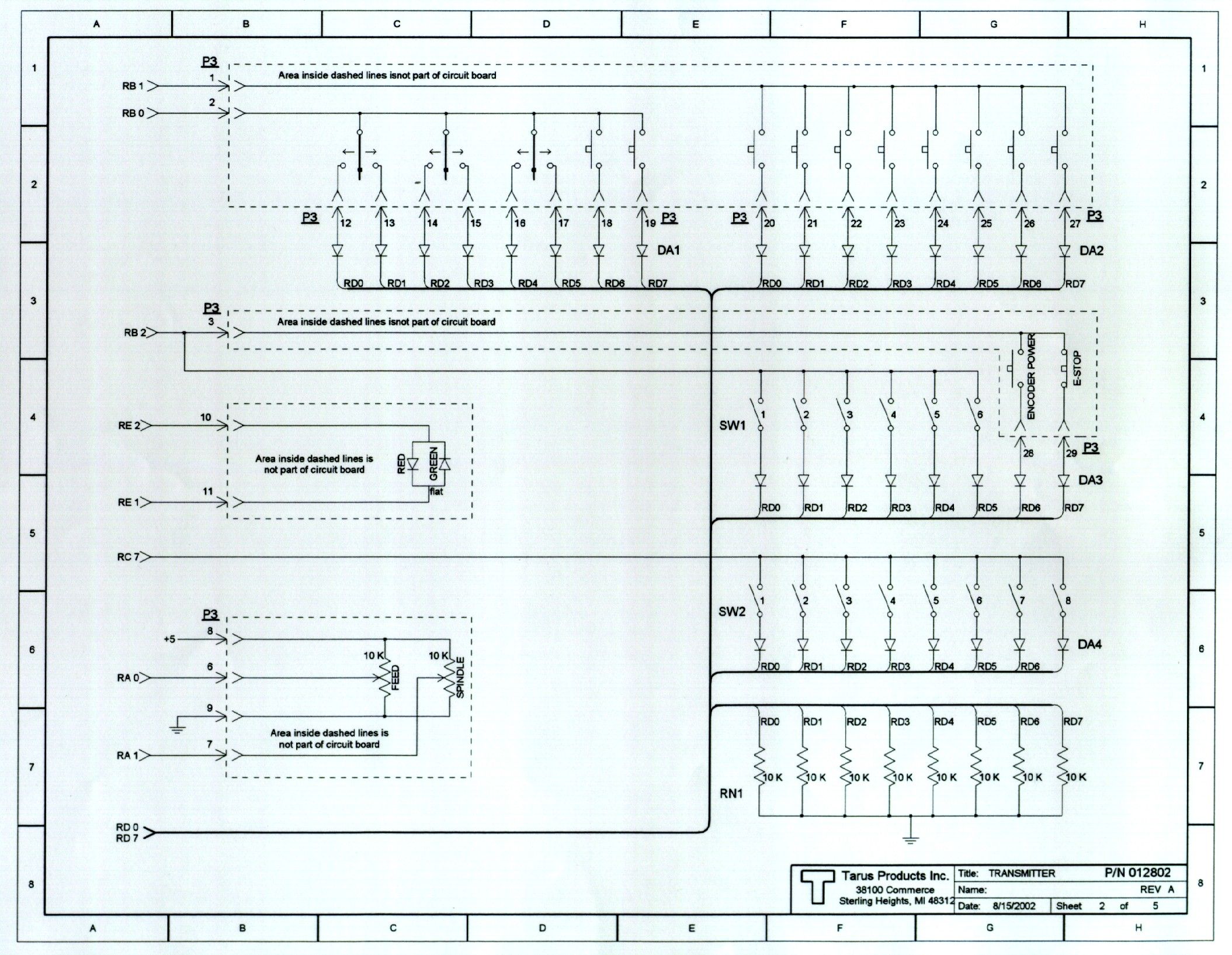
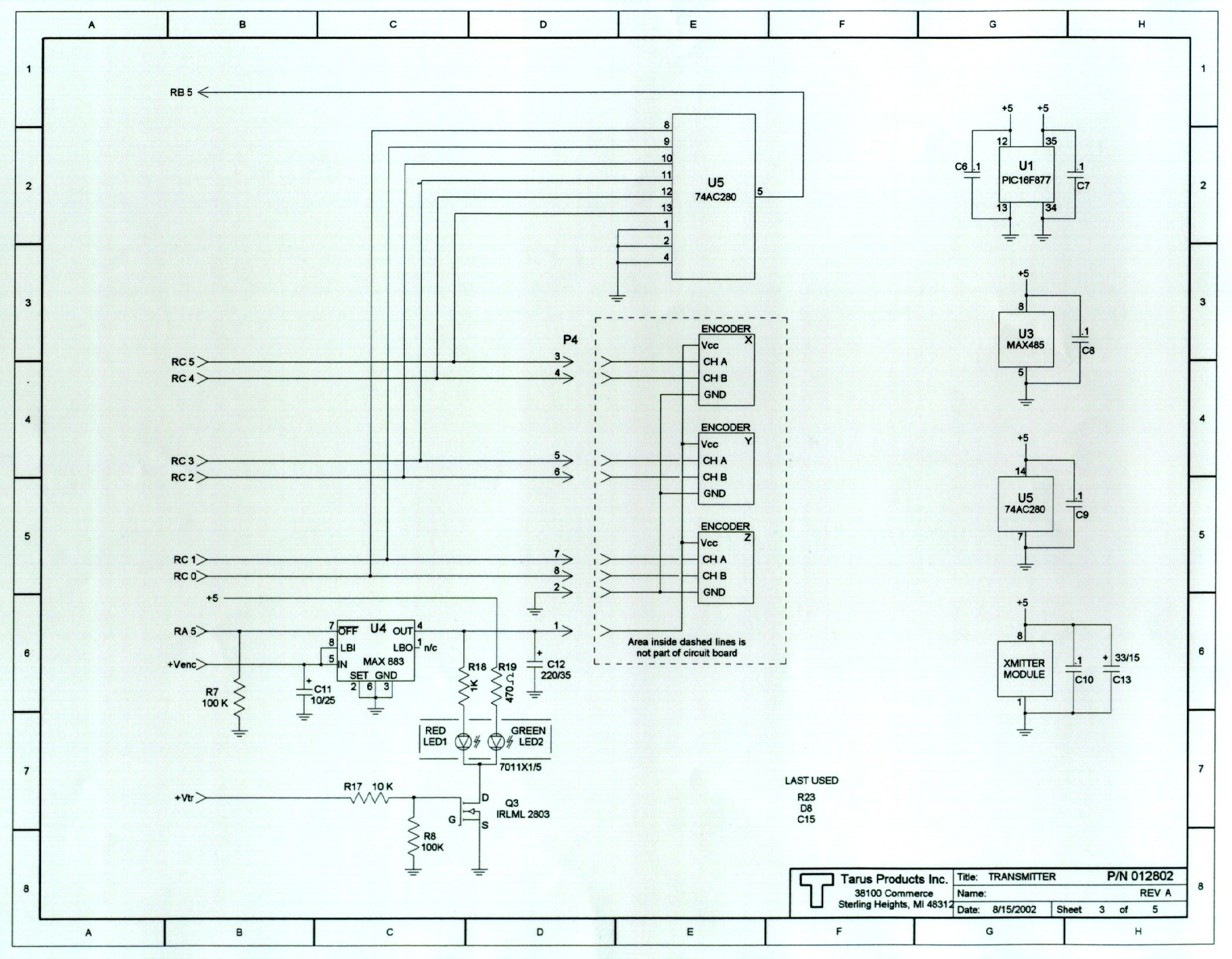
TARUS WIRELESS HANDHELD CONTROL The unit continually scans and transmits to the receiver the state of seventeen switches and two potentiometers. This is acomplished by a microcontroller (Microchip P/N PIC16F877). The microcontroller captures the state (on or off) of the switches and the position of the pots. A preamble is added along with a checksum. This is then sent to the Lynx Technologies HP2 transmitter module in a binary format. The frequency used to transmit the data is determined by the the setting of switches one and two of dip switch SW1. At startup the microcontroller reads these switches and applies them to the HP2 transmitter. The ground plane used for the transmitter is the common of the circuit board to which it is attached. At the receiver any of the seventeen switch that was detected as ON will turn on an open collector output. Depending on the position of the pots, the output voltage for the two will vary from zero to ten volts.
Test Report
A Tarus Products Inc. Application For Certification Radio Remote Control Transmitter (FCC ID: QKFREMOTEASSM)(FCC ID: QKFREMOTEASSM) August 21, 2002 All services undertaken are subject to the following general policy: Reports are submitted for exclusive use of the client to whom they are addressed. Their significance is subject to the adequacy and representative character of the samples and to the comprehensiveness of the tests, examinations or surveys made. No quotations from reports or use of Intertek Testing Services name is permitted except as expressly authorized by Intertek Testing Services in writing. The report must not be used by the client to claim product endorsement by NVLAP or any agency of the U.S. Government. The NVLAP logo is applicable for testing to I EC/CISPR 22:1993 and FCC-47 CFR part 15 only. A TABLE OF CONTENTSTABLE OF CONTENTS 1.01.0General DescriptionGeneral Description.......................................................................................1 1.1Related Submittal(s) Grants..........................................................................1 1.2Product Description...................................................................................1 1.3Test Methodology.....................................................................................1 1.4Test Facility............................................................................................1 2.02.0SystemSystem Test Configuration Test Configuration.............................................................................2 2.1Justification.............................................................................................2 2.2EUT Exercising Software............................................................................2 2.3Special Accessories...................................................................................2 2.4Equipment Modification..............................................................................2 2.5Support Equipment List and Description..........................................................2 2.6Test Configuration Block Diagram.................................................................3 3.03.0Test ResultsTest Results...................................................................................................4 3.1Field Strength of Fundamental and Harmonics Emissions, FCC 15.249(a)(b), 15.205...5 3.2Out of Band Spurious Emissions, FCC 15.249(c), 15.209....................................14 3.3Line Conducted Emissions, FCC 15.207.........................................................18 3.4Test Procedure........................................................................................21 3.5Field Strength Calculation..........................................................................22 4.04.0Test EquipmentTest Equipment.............................................................................................23 EXHIBIT IEXHIBIT I Test Set Up Photographs......................................................................................24 EXHIBIT IIEXHIBIT II FCC ID Label Location........................................................................................29 EXHIBIT IIIEXHIBIT III External Photographs..........................................................................................30 EXHIBIT IVEXHIBIT IV Internal Photographs...........................................................................................32 EXHIBIT VEXHIBIT V Electrical Schematics and Block Diagram..................................................................36 EXHIBIT VIEXHIBIT VI User Manual and Operational Description.................................................................37 A FCC ID: QKFREMOTEASSMAugust 2002 Page 1 of 37 1.0 1.0 GENERAL DESCRIPTIONGENERAL DESCRIPTION 1.1 1.1 Related Submittals GrantsRelated Submittals Grants This is single application of the RADIO REMOTE CONTROL Transmitter for Certification under Part 15 Subpart C. There are no other simultaneous applications. 1.2 1.2 Product DescriptionProduct Description The RADIO REMOTE CONTROL Transmitter is transmitter with attached antenna. The intended use of the RADIO REMOTE CONTROL Transmitter is to generate and transmit a RF encoded binary data signal. The RADIO REMOTE CONTROL Transmitter powered at 12VDC from the SCEPTRE PD1210APL06 120VAC, 60Hz/12VDC Power Adapter or from rechargeable battery located with the Transmitter in the plastic enclosure. The RADIO REMOTE CONTROL Transmitter operates in frequency range from 903.37 to 921.37MHz in eight frequency channels: - channel 0 – 903.37MHz; - channel 1 – 906.37MHz; - channel 2 – 907.87MHz; - channel 3 – 909.37MHz; - channel 4 – 912.37MHz; - channel 5 – 915.37MHz; - channel 6 – 919.877MHz; - channel 7 – 921.37MHz. The RADIO REMOTE CONTROL Transmitter Antenna is ¼ wave rubber duck antenna, SMA-type connector. 1.31.3Test MethodologyTest Methodology Emission measurements were performed according to the procedures in ANSI C63.4-1992. All field strength radiated emissions measurements were performed in the semi-anechoic chamber, and for each scan, the procedure for maximizing emissions in Appendices D and E were followed. All field strength radiated tests were performed at an antenna to EUT distance of 3 meters, unless stated otherwise in the "JustificationJustification SectionSection" of this Application. 1.41.4Test FacilityTest Facility The test site facility used to collect the radiated and conducted measurement data is located at 7250 Hudson Blvd., Suite 100, Oakdale, Minnesota. This test facility has been fully described in a report dated on January 2000 submitted to your office. Please reference the site registration number: 90706, dated May 19, 2000. A FCC ID: QKFREMOTEASSMAugust 2002 Page 2 of 37 2.02.0SYSTEM TEST CONFIGURATIONSYSTEM TEST CONFIGURATION 2.12.1JustificationJustification N/A 2.22.2EUT Exercising SoftwareEUT Exercising Software N/A 2.32.3Special ASpecial Accessoriesccess…
Text truncated - open the document above for the full version.
Test Setup Photos
A FCC ID: QKFREMOTEASSMAugust 2002 Page 24 of 37 EXHIBIT IEXHIBIT I TEST SET UP PHOTOSTEST SET UP PHOTOS A FCC ID: QKFREMOTEASSMAugust 2002 Page 25 of 37 Radiated Emissions Test Configuration A FCC ID: QKFREMOTEASSMAugust 2002 Page 26 of 37 Radiated Emissions Test Configuration A FCC ID: QKFREMOTEASSMAugust 2002 Page 27 of 37 Radiated Emissions Test Configuration A FCC ID: QKFREMOTEASSMAugust 2002 Page 28 of 37 Radiated Emissions Test Configuration
Contact Information
Applicant
VICKY L GREIG(OFFICER)
Technical Contact
Tarus Products, Inc.Tom Dawson
[email protected]586-977-1400
38100 Commerce Drive · Sterling Heights, Michigan · United States
Non-Technical Contact
Intertek Testing Services NA Inc.Yuriy Litvinov
[email protected](651)730-1188
Test Firm
Intertek Testing ServicesUri Spector
Technical Specifications
| # | Rule Parts | Frequency Range | Power Output |
|---|---|---|---|
| 1 | 15C | 903.37 MHz - 921.37 MHz | - |