QL2M3X22 CH Combination FRS/ GMRS Transceiver
Global Link Corporation Limited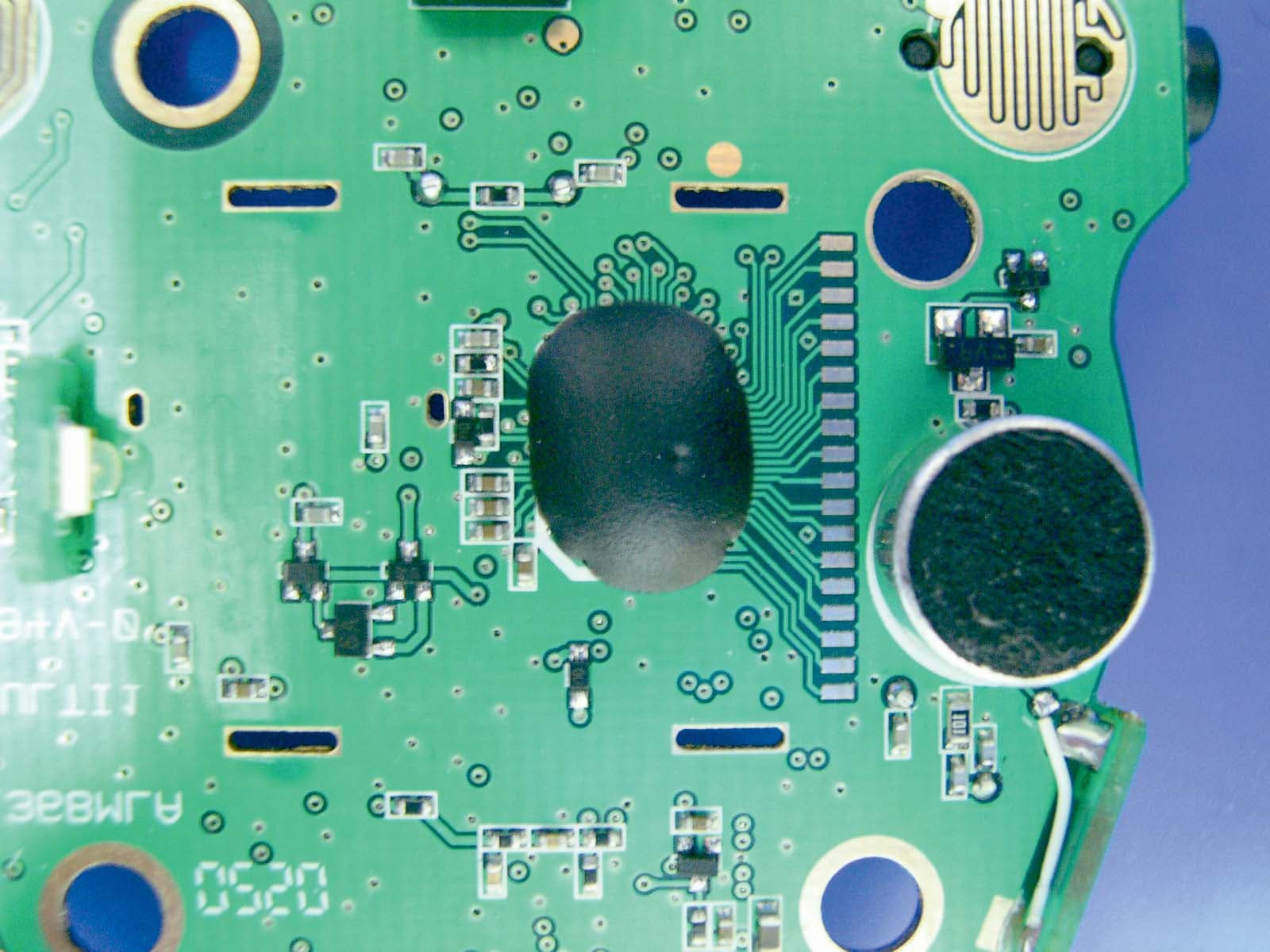
Click to zoom
Application Details
- Equipment Class
- FRF - Part 95 Family Radio Face Held Transmitter
- Date of Grant
- Mar 25, 2003
- Application Purpose
- Original Equipment
- Date of Application
- Mar 25, 2003
- Equipment Note
- 22 CH Combination FRS/ GMRS Transceiver
- Frequency Range
- 462.56250000 - 467.71250000
- Country
- Hong Kong
Documents & Files
Document Text
Text extracted from the exhibit documents filed with the FCC. Open a document above to read the original.
Users Manual
Congratulations on your selection of a quality XACT product. With proper care and adherence to the set-up and user instructions in this Owner’s Manual, this unit will provide you with years of trouble-free service. XACT is committed to providing quality products that fit your needs. We would like to have any comments or suggestions you might have on this product. You may mail your comments to: U.S. Electronics 105 Madison Avenue New York, NY 10016 The M3X is the newest generation in personal two-way communications. The M3X is a lightweight, compact two-way communication device that can be used to communicate with family or friends at parks, shopping malls, sporting events, concerts – any indoor or outdoor activity. Here are some of the features of this new two-way COMMUNICATOR: • Pendant Style with Detachable Neck Band • 22 FRS/GMRS Channels • Up to 2.0 Mile Range • Auto Squelch • Auto Battery Saving • Internal VOX • Channel Scan • 12 Hour AM/PM Time Clock • Backlit LCD Display on COMMUNICATOR Mode • Uses 3 AAA size Alkaline battery with Ni-MH battery capability (not included) Please read this Owner’s Manual carefully to get the most out of your TWO-WAY COMMUNICATOR. NOTE: The maximum range will vary depending on terrain and environment. Range will be greater in open fields. While range is shorter within and around buildings or large structures. This unit may not ensure privacy of communication. Safety Information : Your wireless hand-held portable transceiver contains a low power transmitter. When the Push-to-Talk (PTT) key is pushed it sends out COMMUNICATOR frequency (RF) signals. This devise is authorized to operate at a duty factor not to exceed 50%. In August 1996, The Federal Communications Commission (FCC) adopted RF exposure guidelines with safety levels for hand-held wireless devices. Important Note: To maintain compliance with the FCC’s RF exposure guidelines, hold the transmitter and ANTENNA at least 1 inch (2.5 centimeters) from your face and speak in a normal voice, with the antenna pointed away from the face. If you wear the handset on your body while using the headset accessory, use only the manufacturer’s supplied BELT CLIP for this product and ensure that the ANTENNA is at least 1 inch (2.5 centimeters) from your body when transmitting. Use only supplied ANTENNA. Unauthorized antennas, modifications, or attachments could damage the transmitter and may violate FCC regulations. This device complies with Part 15 of the FCC Rules. Operation is subject to the following two conditions: (1) this device may not cause harmful interference, and (2) this device must accept any interference received, including interference that may cause undesired operation. FEATURES FCC NOTICE 1. Channel Number (1~22) – Shows the current channel 2. Transmit Indicator (TX) – Indicates when the unit is transmitting 3. Receive Indicator (RX) – Indicates when the unit is receiving a transmission 4. Volume Selection (8 Bars) – Shows the current volume setting 5. Call Tone Transmission (CALL) – Indicates when the unit is paging 6. Low Battery Level indicator - Indicates when battery level is low or during charging the battery 7. VOX – Indicates when unit is in VOX mode 8. 12 Hour Time Clock (12:00) 9. Power / Menu (Multi Function) – Press and hold to turn the COMMUNICATOR ON/OFF. Momentary press will enter the Menu and Clock setting. 10. PTT / Call (Multi Function) – Press and hold to transmit voice communication. Press twice in rapid action to transmit call tone. 11. Up – Used to adjust volume level (default), change channel and clock setting (in Menu) 12. Down – Used to adjust volume level (default), change channel and clock setting (in Menu) 13. Scan – Press to enter Channel Scan. 14. MIC – Built-in microphone 15. Speaker – Built-in speaker 16. Antenna DISPLAYS KEYS and CONTROLS 1 2 3 4 5 6 7 8 16 15 14 13 12 11 10 9 Your M3X COMMUNICATOR uses 3 AAA size Alkaline battery. To install the battery: 1. Release the Battery Compartment Cover Latch located on the rear side of the unit, and remove the Battery Compartment Cover from the Battery Compartment. 2. Install the batteries into the Battery Compartment. Be certain to follow the correct battery orientation in the compartment. Installing the batteries incorrectly will prevent the unit from operating. 3. Replace the Battery Compartment Cover and lock the Battery Compartment Cover Latch into position. In Watch and COMMUNICATOR Mode the Low Battery Level icon will not appear on the display unless the unit detects that the battery is low. The unit has a Low Battery Level icon which will blink when it detects a low battery level in COMMUNICATOR and in Watch Mode. When the unit is in COMMUNICATOR Mode or Watch Mode and the battery level is low the icon will blink. You should replace the batteries by this time to continue operation. Your COMMUNICATOR has the capability to use Ni-MH batteries, if you are using Ni-MH batteries you should recharge the batteries when the level becomes low. You can recharge the batteries thru the Headset / Charger jack found at the side of the unit. Your M3X COMMUNICATOR comes with an A/C Adapter Charger to charge your Ni-MH batteries. To charge the batteries: 1. Lift the Headset / Charger Jack Cover located in the side of your unit. 2. Connect the A/C Adapter Charger into an A/C Wall outlet 2. Insert the A/C Adapter Charger into the Headset / Charger Jack. During charging, the Low Battery Level icon will disappear on the display once the battery level is above the Low Level limit. BATTERY INSTALLATION CAUTION: To reduce the risk of fire or personal injury, use only the battery listed in the instruction book. The M3X has a built in Power Saver feature for maximum battery life. But when the M3X is not being used, conserve battery power by pressing the Power Key to OFF. Remove the battery if the unit will not be used for a long period of time. ! Battery Compartment Cover Latch Battery Compartment CHARGING THE BATTERY Headset/Charger …
Text truncated - open the document above for the full version.
Cover Letter(s)
Correspondence Summary Questions and Answers March 21, 2003 SUBJECT: GLOBAL LINK CORPORATION LIMITED - FCC ID: QL2M3X TCB Q-1: The device has a connector for recharging Nickel Metal Hydride batteries using an AC/DC power adapter. Can the transmitter be operated why charging the batteries? If so, please provide conducted spurious emissions test data per part15.207. Applicant A-1: The unit cannot transmit when the power adapter is plugged into the device to charge the batteries. TIMCO ENGINEERING INC. 849 NW State Road 45 Newberry, Florida 32669 http://www.timcoengr.com 888.472.2424 F 352.472.2030 [email protected]
Operational Description
BUB TECHNICAL DESCRIPTION Page 1 Feb 12, 2003 A). GENERAL DESCRIPTION The Bub GMRS radio is a self-contained transceiver unit with integral antenna intended for use as a general communication tool. It is designed to operate on all 22 channels allocated by the FCC for the licensed GMRS. The useable range, while dependent upon terrain and other radio propagation principles, is typically two miles. The Bub uses the maximum transmit power allowed to help ensure the maximum communication range. Features include: 22 GMRS Channels, Digital Receive Volume Control, Page and LCD Display. The unit is equipped with an external Headset option connector. 3 Alkaline battery that are readily available in market retail outlets supply operating power. An automatic power savings feature allows the typical standby battery life to extend to more than 7 days. B). FREQUENCY DETERMINING CIRCUITS The fundamental frequency for both the transmitter and the receiver local oscillators are controlled by a phase lock loop (PLL) circuit Combo1 (Panasonic An6311 or equipvalent). The frequency of operation of the GMRS voltage controlled oscillator (VCO), composed of Q301 and Q302 operating in cascade is phase locked to a voltage controlled crystal reference (VCXO) operating at 20.95MHz (X202). The VCO is locked to the fundamental of the transmit signal in the transmit mode and is locked to the receive 1 st LO (Fundamental channel frequency minus 21.4MHz) in the receive mode. The crystal reference frequency is shared with the 2 nd LO of 20.95MHz. C). TRANSMITTER CIRCUITS The transmit ter amplifies the 0 dBm signal from the VCO to approximately 20.6 dBm that is fed to the antenna. The transmitter is a three stage amplifier composed of Q1,4 and Q11. The first two stages are operated class A and the final is operated class B in full saturation to help prevent unwanted amplitude modulation. The fundamental transmit signal is fed through an elliptical low pass filter (5-pole, 2 zero) in order to suppress the harmonics to below –60 dBc. The desired frequency modulation of the carrier is accomplished by modulating the current in the VCO directly with the microphone audio signal. The microphone audio is conditioned with a three-pole high pass filter at 300 Hz (Combo1, Mic Amp.), a hard clipper circuit (Combo1) to limit maximum deviation to +/- 2.5 kHz and a three-pole low pass or splatter filter at 2.8 kHz BUB TECHNICAL DESCRIPTION Page 2 (Combo1, SP amp.). The low pass filter insures that the occupied bandwidth of the FM modulated signal meets FCC requirements under all input conditions. D). RECEIVER CIRCUITS The received signal from the antenna is band limited to 600 Mhz by the transmitter harmonic filter. The desired signal is fed to a low noise amplifier (LNA – Q6) centered from 460 to 470 MHz that provides approximately 10 dB of gain. The output of the LNA is filtered with a Band Pass filter (C41,L16,C43,L17,C15,L36) with pass-band of 460 to 470 MHz and stopband attenuation of 10 dB. The filtered receive signal is one input to the 1 st mixer (Q8), the other mixer input (1 st LO) is the output of the VCO at the desired channel frequency minus 21.4MHz. The output of the mixer is tuned to the 1 st IF of 21.4 MHz. The 1 st IF is transformer coupled for impedance matching to a X-tal filter centered at 21.4MHz with a bandwidth of 3.75KHz. The filtered 1 st IF is then amplified by Combo1 and fed to the 2 nd mixer. The 2 nd LO (20.95 MHz) is generated by VCXO that is the reference frequency for the PLL of Combo1. The 2 nd mixer output of 450 kHz is filtered through a 4 section ceramic filter that in combination with the 21.4 MHz X-tal filter provides approximately 50 dB of adjacent channel attenuation. The 450 kHz 2 nd IF is then amplified, limited and fed to a quadrature detector for FM demodulation. The resulting audio output signal is highpass filtered from 300 (Combo1) and amplified to provide 200mW of audio power (IC2). A squelch circuit is provided (Combo1 pins 29 through 30) to mute the receiver noise under low signal conditions. The squelch circuit amplifies and detects noise in a narrow bandwidth at approximately 5 kHz. When the detected noise exceeds a threshold set to trigger at approximately 12 dB SINAD receive signal strength, the audio output is muted. E). TRANSMIT/RECEIVE SWITCH When the radio is in the transmit mode, pin diode switches D1 and D2 are both turned on (representing less than 0.7 ohms). D2 allows the transmit signal to pass to the antenna and D1 shorts one leg of a T matching network (L3, L15 and C4) to ground in the receive path. This results in a parallel tuned circuit high impedance being presented to the transmit signal so that the receive path does not load the transmit signal. In the receive mode, both D1 and D2 are off, resulting in the antenna signal being coupled into the receive LNA through the 50 ohm T matching network and the unwanted load of the transmit final amplifier is reduced to less than 1 pF by D1. F). RADIO CONTROL CIRCUIT A microprocessor (U1) is used to control the transceiver. User stimuli is provided through a tack switch for PTT (push to talk), along with the keypad for channel selection, receive volume, and page. Pressing the PTT switch instructs U1 to switch to the transmit mode. This is accomplished by loading the proper channel counter information through a 3-wire serial link to the PLL of Combo1, turning on power to the PLL and VCO, microphone and transmit audio circuits and the transmit RF amplifiers. Pressing the call BUB TECHNICAL DESCRIPTION Page 3 switch causes the microcontroller to transmit a warbling tone for approximately 5 seconds on the current channel selected that is used to notify another person with GMRS radio that you wish to communicate. Pressing the channel Up/Down buttons (active in receive mode only) instructs U1 to increment or decrement respectively the channel frequency by one channel from the channel previously selected. In receive mode the microcontr…
Text truncated - open the document above for the full version.
Test Report
APPLICANT: GLOBAL LINK CORPORATION LIMITED FCC ID: QL2M3X REPORT #: G/GlobalLink_QL2\290UT3\290UT3TestReport.doc TABLE OF CONTENTS TABLE OF CONTENTS LIST APPLICANT: GLOBAL LINK CORPORATION LIMITED FCC ID: QL2M3X TEST REPORT: PAGE 1......GENERAL INFORMATION & TECHNICAL DESCRIPTION PAGE 2......TECHNICAL DESCRIPTION CONTINUED & RF POWER OUTPUT PAGE 3......MOD. CHARACTERISTICS & AUDIO FREQUENCY RESPONSE GRAPH PAGE 4......MODULATION LIMITING GRAPH – 300 Hz & 1000 Hz PAGE 5......MODULATION LIMITING GRAPH – 2500 Hz PAGE 6......AUDIO LOW PASS FILTER GRAPH PAGE 7......OCCUPIED BANDWIDTH PAGE 8......OCCUPIED BANDWIDTH PLOT PAGE 9......SPURIOUS EMISSIONS AT ANTENNA TERMINALS PAGE 10.....UNWANTED RADIATION – GMRS PAGE 11.....UNWANTED RADIATION - FRS PAGE 12.....METHOD OF MEASURING RADIATED SPURIOUS EMISSIONS PAGE 13.....FREQUENCY STABILITY PAGE 14-16..LIST OF TEST EQUIPMENT EXHIBITS CONTAINING: EXHIBIT 1.........FCC ID LABEL SAMPLE EXHIBIT 2.........LABEL LOCATION EXHIBIT 3.........EXTERNAL & INTERNAL PHOTOGRAPHS EXHIBIT 4.........BLOCK DIAGRAM EXHIBIT 5.........SCHEMATICS EXHIBIT 6.........USER'S MANUAL EXHIBIT 7.........THEORY OF OPERATION EXHIBIT 8.........TUNING PROCEDURE EXHIBIT 9.........PARTS LIST EXHIBIT 10........SPECIFICATION SHEET EXHIBIT 11........SAR TES REPORT EXHIBIT 12........TEST SET UP PHOTOGRAPH APPLICANT: GLOBAL LINK CORPORATION LIMITED FCC ID: QL2M3X REPORT #: G/GlobalLink_QL2\290UT3\290UT3TestReport.doc Page 1 of 16 GENERAL INFORMATION REQUIRED FOR CERTIFICATION 2.1033(c)(1)(2) GLOBAL LINK CORPORATION LIMITED will manufacture the FCCID: QL2M3X GMRS/FRS COMBINATION TRANSCEIVER in quantity, for use under FCC RULES PART 95. GLOBAL LINK CORPORATION LIMITED ROOM 13B, CHINA MINMETALS TOWER 79 CHATHAM ROAD SOUTH TSIM SHA TSUI, KOWLOON, HONG KONG 2.1033 (c) TECHNICAL DESCRIPTION 2.1033(c)(3) Instruction book. A draft copy of the instruction manual is included as EXHIBIT 6. 2.1033(c) (4) Type of Emission: 10K5F3E 95.631 Bn = 2M + 2DK M = 3000 D = 2.250K Bn = 2(3000)+2(2250) = 10.5K GMRS Authorized Bandwidth 20.0 kHz 2.1033(c)(5) GMRS Frequency Range: 1. 462.5500 13. 462.7000 95.621 2. 462.5625 14. 462.7125 3. 462.5750 15. 462.7250 4. 462.5875 16. 467.5500 5. 462.6000 17. 467.5750 6. 462.6125 18. 467.6000 7. 462.6250 19. 467.6250 8. 462.6375 20. 467.6500 9. 462.6500 21. 467.6750 10. 462.6625 22. 467.7000 11. 462.6750 23. 467.7250 12. 462.6875 FRS Authorized Bandwidth 12.5KHz 2.1033(c)(5) FRS Frequency Range: 1. 462.5625 8. 467.5625 95.627 2. 462.5875 9. 467.5875 3. 462.6125 10. 467.6125 4. 462.6375 11. 467.6375 5. 462.6625 12. 467.6625 6. 462.6875 13. 467.6875 7. 462.7125 14. 467.7125 MHz 2.10311c)(6)(7) RF power is measured by the substitution method as 2.1046(a) outlined in TIA/EIA - 603. With a nominal battery voltage of 4.5 VDC, and the transmitter properly adjusted the RF output measures: GMRS - .115 Watts FRS - .104 Watts APPLICANT: GLOBAL LINK CORPORATION LIMITED FCC ID: QL2M3X REPORT #: G/GlobalLink_QL2\290UT3\290UT3TestReport.doc Page 2 of 16 2.1033(c)(6)(7) Power Output shall not exceed 0.50 Watts effective 95.639 radiated power. There can be no provisions for 95.649 increasing the power or varying the power. 2.1033(c)(8) DC Voltages and Current into Final Amplifier: FINAL AMPLIFIER ONLY FOR LOW POWER SETTING INPUT POWER: (4.5V)(.560A) = 2.52 Watts FOR HIGH POWER SETTING INPUT POWER: (4.5V)(.560A) = 2.52 Watts 2.1033(c)(9) Tune-up procedure. The tune-up procedure is included as EXHIBIT # 8. 2.1033(c)(10) Complete Circuit Diagrams: The circuit diagram is included as EXHIBIT 5 of this report. The block diagrams are included as EXHIBIT 4 of this report. 2.1033(c)(11) A photograph or a drawing of the equipment identification label is included as exhibit No. 1-2. 2.1033(c)(12) Photographs(8"X10") of the equipment of sufficient clarity to reveal equipment construction and layout, including meters, labels for controls, including any view under shields. See exhibits 3. 2.1033(c)(13) Digital modulation is not allowed. 2.1033(c)(14) The data required by 2.1046 through 2.1057 is submitted below. 2.1046(a) RF power output. The test procedure used was TIA/EIA-603 §2.2.1. APPLICANT: GLOBAL LINK CORPORATION LIMITED FCC ID: QL2M3X REPORT #: G/GlobalLink_QL2\290UT3\290UT3TestReport.doc Page 3 of 16 APPLICANT: GLOBAL LINK CORPORATION LIMITED FCC ID: QL2M3X REPORT #: G/GlobalLink_QL2\290UT3\290UT3TestReport.doc Page 4 of 16 2.1047(a)(b) Modulation characteristics: AUDIO FREQUENCY RESPONSE The audio frequency response was measured in ac- cordance with TIA/EIA Specification 603. The audio frequency response curve is shown on the next page. The audio signal was fed into a dummy microphone circuit and into the microphone connector. The input required to produce 30 percent modulation level was measured. See plot below. Audio Frequency Response -25 -20 -15 -10 -5 0 5 10 100100010000 Frequency Hz Attenuation dB APPLICANT: GLOBAL LINK CORPORATION LIMITED FCC ID: QL2M3X REPORT #: G/GlobalLink_QL2\290UT3\290UT3TestReport.doc Page 5 of 16 2.1047(b) Audio input versus modulation The audio input level needed for a particular per- percentage of modulation was measured in accor- dance with TIA/EIA Specification 603. The audio input curves versus modulation are on the following pages. Curves are provided for audio input frequen- cies of 300, 1000, and 3000 Hz. See Pages 4 and 5 of report. MODULATION LIMITING PLOT – 300 Hz MODULATION LIMITING PLOT – 1000 Hz 0 0.5 1 1.5 2 2.5 3 -90-80-70-60-50-40-30-20-10010 dBm Deviation 0 0.5 1 1.5 2 2.5 3 -90-80-70-60-50-40-30-20-10010 dBm Deviation APPLICANT: GLOBAL LINK CORPORATION LIMITED FCC ID: QL2M3X REPORT #: G/GlobalLink_QL2\290UT3\290UT3TestReport.doc Page 6 of 16 MODULATION LIMITING PLOT – 2500 Hz 0 0.5 1 1.5 2 2.5 3 -90-80-70-60-50-40-30-20-10010 dBm Deviation APPLICANT: GLOBAL LINK CORPORATION LIMITED FCC ID: QL2M3X REPORT #: G/GlobalLink_QL2\290UT3\290UT3TestReport.doc Page 7 of 16 95.637 Post Limiter Filter Each GMRS transmitter, except a mobile station transmitte…
Text truncated - open the document above for the full version.
Contact Information
Applicant
Ki Choi(Marketing Manager)
Test Firm
Timco Engineering, Inc.S Sanders
Technical Specifications
| # | Rule Parts | Frequency Range | Power Output | Emission | Tolerance |
|---|---|---|---|---|---|
| 2 | 95B | 462.5625 MHz - 467.7125 MHz | 104.00 mW | 10K5F3E | 2.5 ppm |
Other Applications from Global Link Corporation Limited
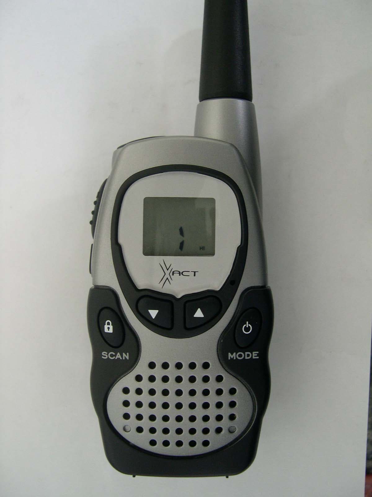
QL2GMRS2104
Apr 06, 2004FRS/GMRS
Equipment Class
FRF - Part 95 Family Radio Face Held Transmitter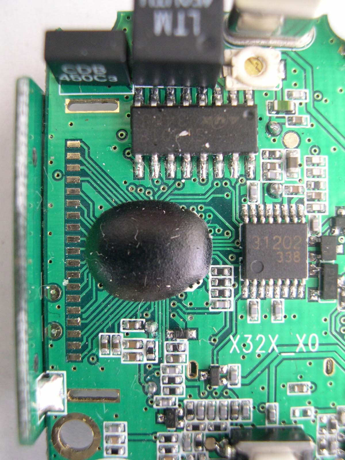
QL2FRSX32X
Mar 15, 2004FRS/GMRS
Equipment Class
FRT - Part 95 Family Radio Body Worn Transmitter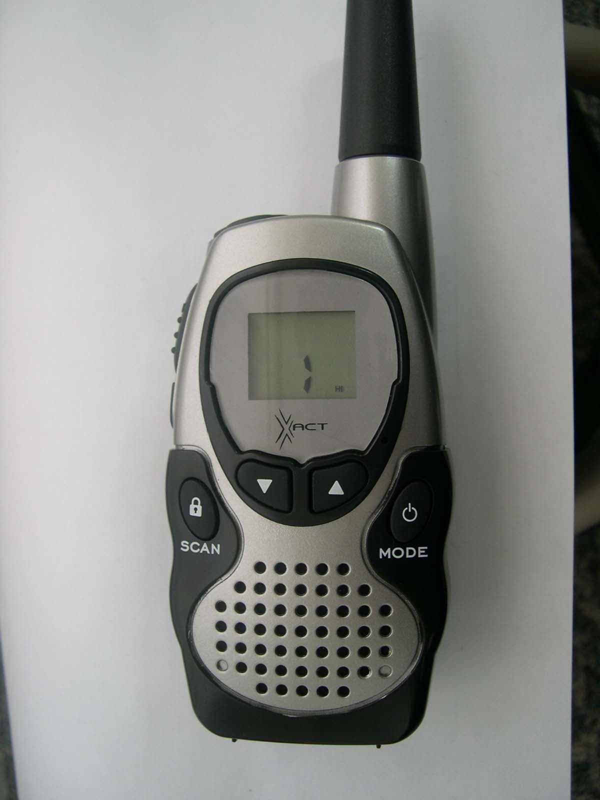
QL2GMRSXGM950
Dec 14, 2003FRS/GMRS
Equipment Class
FRF - Part 95 Family Radio Face Held Transmitter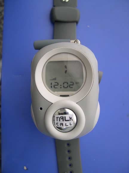
QL2FRSKP3X
Jul 01, 200314 CH FRS TRANSCEIVER - TRANSMITTER
Equipment Class
FRF - Part 95 Family Radio Face Held Transmitter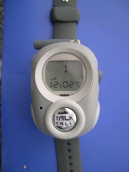
QL2FRSFW14
Jul 01, 200322 CH FRS/GMRS COMBINATION TRANSCEIVER
Equipment Class
FRF - Part 95 Family Radio Face Held Transmitter