QL3SHR5016Digital Video Recorder
KODICOM CO., Ltd.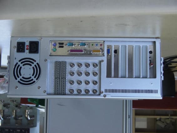
Click to zoom
Application Details
- Equipment Class
- JBC - Part 15 Class B Computing Device/Personal Computer
- Date of Grant
- Sep 15, 2002
- Application Purpose
- Original Equipment
- Date of Application
- Sep 15, 2002
- Equipment Note
- Digital Video Recorder
- Company
- KODICOM CO., Ltd.
- Country
- South Korea
Documents & Files
Document Text
Text extracted from the exhibit documents filed with the FCC. Open a document above to read the original.
Users Manual
DIGITAL RECORDING SYSTEM Note : This equipment has been tested and found to comply with the limits for a Class B digital device, pursuant to part 15 of the FCC Rules. These limits are designed to provide reasonable protection against harmful interference in a residential installation. This equipment generates, uses and can radiate radio frequency energy and, if not installed and used in accordance with the instructions, may cause harmful interference to radio communications. However, there is no guarantee that interference will not occur in a particular installation. If this equipment does cause harmful interference to radio or television reception, which can be determined by turning the equipment off and on, the user is encouraged to try to correct the interference by one or more of the following measures : - Reorient or relocate the receiving antenna. - Increase the separation between the equipment and receiver. - Connect the equipment into an outlet on a circuit different from that to which the receiver is connected. - Consult the dealer or an experienced radio/TV technician for help. ’” I II III IV I. I ❶ ❷ ❸ ❹ ❺ ❻ ❼ ❽ ❾ Feature Display current date and time PAN/TILT: controls camera in left and right / up and down / FOCUS : adjust focus of the camera lens. (not applied to AUTO FOCUS lens) ZOOM: adjust Zoom In/ Zoom Out of the camera P/T Speed: adjust Speed Dome camera’s movement speed PreSet setup : PreSet setup for Auto PAN/TILT function ❶ ❷ ❸ ❹ ❺ ❻ ❼ ❽ Auto Preset : Camera tours automatically along the configured path. Up, down or left, right button cane stop auto function. PAN/TILT number: You can move camera toward the position recorded. Display mode : convert from PAN/TILT mode to Live display mode ❾ 9 II ❶ ❷ ❸ ❹ ❺ ❻ ❼ ❽ ❾ ❶ ❷ ❸ ❹ ❺ ❻ ❼ ❽ ❾ ZOOM: adjust Zoom In/ Zoom Out of the camera FOCUS : adjust focus of the camera lens. (not applied to AUTO FOCUS lens) PAN/TILT: controls camera in left and right / up and down / II. Í Î • • • • • • • • • • • • 5 Motion detection Motion detection screen Select Camera : Select the camera to setup Feature Screen Description System starts recording when it detects any activity in the detection area without using sensors. Sensitivity : Adjust the motion detection sensitivity Default value is “80”, which is the most proper Detection area Motion Detection Area Select the camera number and draw detection area using left click dragging. Maximum five detection area can be made. To remove the selected motion detection area drag mouse pointer toward out of box. Area draw Default Restore the default color configuration for the camera by clicking [Default] button Alarm(M) : System makes beeping sound to alert when there is any activity in the selected time. When Alarm(M) button is pressed on : Alarm beeping works. When Alarm(M) button is not pressed on : Alarm beeping does not work. System beeps only when activity is detected in the selected time zone in recording schedule. System does not beep if the camera is set to ‘continuous recording’ Brightness / Hue / Contrast : Adjust Brightness, hue,and contrast Default for camera is ‘18 / 8 /10’ , and the range is -127~126 and adjustable to each camera. (Proper setup is required depending on site situation) 6 Network Network Sensor for emergency : If the sensor detects any signal it sends alarm to Center with the recorded image during the designated time. Click the sensor number to configure Feature Emergency phone numbers : When the first trial fails to connect, it tries to connect to the second number which is emergency phone number. This is to transmit emergency image or message. Select [Emergency phone numbers] button and input emergency phone number. Up to two emergency phone number can be used. Emergency IP address : Transmit emergency image or message by connecting to the assigned IP address. Click [Emergency IP address] button and input IP address. Transfer time : Select the duration in sec how long it will send images to Center on connection. If any new signal is detected while connection, image transfer time starts again. [Notice] When you try to connect to site from Center, DigiNet checks the site code and password together. Type of connection For remote connection LAN, PSTN, ISDN, Leased Circuit can be used. ISDN or Leased Circuit using router can be used. ISDN or PSTN can be used to connect to DVR without router directly. Check on “No Use” for no connection Password : Input required password to connect from Center p.c. (4 digit number is possible.) [Password] : Input password required to access to DVR from Center. [Confirm] : Input once again to confirm. Default value is “1234” PPP Setup for PSTN/ISDN connection without router PPP Setup using KPPPSetup.exe • To setup PSTN connection first install Modem in Windows. Then execute a file named “KPPPSetup.exe” both in site and center and the required setup will be made automatically. Required step before Installation •In order to use KPPPSetup.exeprogram, CD-Rom drive may ask you to put in the original Windows98 Second Edition or hard diskette must be copied with original file of Windows98 Second Edition. •This program may not work properly when the system doesn’t have a modem installed. • If a modem is not installed, first install modem and driver for that. Then execute KPPPSetup.exe PSTN or ISDN setup on Windows98 Install a modem for PSTN connection and ISDN Terminal Adapter for ISDN connection. Execute KPPPSetup.exe Reboot system after PPP setup is done. Please check the connection between Center and Site after rebooting the system. [Notice] • The system may request you original Windows98SE CD, then assign the path of Windows98SE. • For ISDN connection without router, follow the same step as required on PSTN. In other words, just execute KPPPSetup.exe Items that will be installed by KPPPSetup.exe • Dial-up Networking • Dial-Up server • Phone Dialer • Dial-Up Adapter • TCP/IP Protocol • Modification in Dial-up Server properties Notice • Any windows o…
Text truncated - open the document above for the full version.
Block Diagram
DVR DVR BLOCK DIAGRAM BLOCK DIAGRAM AC IN POWER SUPPLY (SPC-300-12V) MAIN BOARD (ASUS P4B) 24MHz 14MHz CAPTURE BOARD (SDC-1000) 28MHz CAMERA MOUSE, KEY BOARD I/O BOARD (SDI-1000) 11MHz SENSOR CONTROL RS-485 HDD, DVD... RECORDER VIDEO SIGNAL INPUT MONITOR DISPLAY DC IN CONTROL POWER LIGHT OTHER MACHINE CONTROL VGA BOARD (ATI RADEON VE) 27MHz MIC AUDIO BOARD (SDA-1000) 19MHz
Test Report
ERI Electromagnetic research institute 66-6, JEIL-RI, YANGJI-MYUN, YOUNGIN-CITY, KYUNGGI-DO, KOREA TEL: 82 31 336 1186 FAX : 82 31 336 1184 homepage : www.eri.re.kr ReportNo.:ERI-FCC-0140 Page : 1 of 16 EMI TEST REPORT Test report No.: ERI-FCC-0140 Type of equipment: Digital Video Recorder Model name: SHR-5016 Applicant: KODICOM Co.,Ltd. Test standards: FCC Part 15 Subpart B (Class B) Test Procedure and Items : - AC Power line Conducted emissions measurement: ANSI C63.4-1992 - Radiated emissions measurement: ANSI C63.4-1992 Test result : Pass This equipment has been tested to comply with the requirements of FCC Rules and Regulations Part 15 Subpart B unintentional Radiators. The results in this report apply only to the sample tested. This test report shall not be reproduced except in full, without the written approval of ERI Laboratory. Date of test: 2002. 8. 198. 28 Issued date: 2002. 8. 29 Tested by : Approved by: SEJIN, O SANG-KYU, LEE ERI Electromagnetic research institute 66-6, JEIL-RI, YANGJI-MYUN, YOUNGIN-CITY, KYUNGGI-DO, KOREA TEL: 82 31 336 1186 FAX : 82 31 336 1184 homepage : www.eri.re.kr ReportNo.:ERI-FCC-0140 Page : 2 of 16 Contents 1. Client information 2. Laboratory information 3. Test system configuration 3.1 Operation environment 3.2 Measurement uncertainty 3.3 Sample calculation 4. Description of E.U.T. 4.1 Product description 4.2 Peripherals 4.3 Used cables 4.4 E.U.T. test configuration 4.5 Operating conditions 5. Test results 5.1 Conducted emission 5.1.1 Measurement procedure 5.1.2 Used equipments 5.1.3 Measurement uncertainty 5.1.4 Test data 5.1.5 Test result ERI Electromagnetic research institute 66-6, JEIL-RI, YANGJI-MYUN, YOUNGIN-CITY, KYUNGGI-DO, KOREA TEL: 82 31 336 1186 FAX : 82 31 336 1184 homepage : www.eri.re.kr ReportNo.:ERI-FCC-0140 Page : 3 of 16 5.2 Radiated emission 5.2.1 Measurement procedure 5.2.2 Used equipments 5.2.3 Measurement uncertainty 5.2.4 Test data 5.2.5 Test result 6. Photographs Conducted emission test Radiated emission test EUT(Front, Rear, Inner, Mainboard front, rear) Attached : Conducted emission graph ERI Electromagnetic research institute 66-6, JEIL-RI, YANGJI-MYUN, YOUNGIN-CITY, KYUNGGI-DO, KOREA TEL: 82 31 336 1186 FAX : 82 31 336 1184 homepage : www.eri.re.kr ReportNo.:ERI-FCC-0140 Page : 4 of 16 1. Client information Applicant/Manufacturer: KODICOM Co., Ltd. Address : 5 th floor, A Dong, SK Twin Tower, 345-9, Gasan Dong, Gumchon-Ku, Seoul, Korea Telephone number: + 82-2-529-5768 Facsimile number: + 82-2-579-8419 2. Laboratory information Address The open area test site and EMC facilities are used for these testing. This facility was accredited by KOLAS, EK of Korea, MIC, FCC. EMC RESEARCH INSTITUTE . 66-6, JEIL-RI, YANGJI-MYUN, YOUNGIN-CITY, KYUNGGI-DO, KOREA Telephone Number : 82- 31- 336- 1186 Facsimile Number : 82- 31- 336 -1184 KOLAS No.: 111 EK: J MIC: KR0030 FCC Filing No.: 302567 ERI Electromagnetic research institute 66-6, JEIL-RI, YANGJI-MYUN, YOUNGIN-CITY, KYUNGGI-DO, KOREA TEL: 82 31 336 1186 FAX : 82 31 336 1184 homepage : www.eri.re.kr ReportNo.:ERI-FCC-0140 Page : 5 of 16 3. TEST SYSTEM CONFIGURATION 3.1 Operation environment TemperatureHumidityPressure 10m Chamber : 21.0C 52 %- Shielded room :24.0C58 %998hPa 3.2 Measurement Uncertainty All measurements involve certain levels of uncertainties, specifically in field of EMC. The factors contributing to uncertainties are test receiver, Cable loss, antenna factor calibration, Antenna directivity, antenna factor variation with height, antenna phase center variation, antenna Frequency interpolation, measurement distance variation, site imperfection, mismatch, and system repeatability. Based on NIS 80,81, The measurement uncertainty level with a 95% confidence level were applied. ERI Electromagnetic research institute 66-6, JEIL-RI, YANGJI-MYUN, YOUNGIN-CITY, KYUNGGI-DO, KOREA TEL: 82 31 336 1186 FAX : 82 31 336 1184 homepage : www.eri.re.kr ReportNo.:ERI-FCC-0140 Page : 6 of 16 3.3 Sample calculation Conducted emission The field strength is calculated by adding the LISN factor, cable loss from the measured reading. The sample calculation is as follows : FS = MR + LF + CL MR = Meter Reading LF = LISN Factor CL = Cable Loss If MR is 30dB, LISN Factor 1dB, CL 1dB The result (MR) is 30 + 1 + 1 = 32dBuV Radiated emission The field strength is calculated by adding the antenna Factor, cable loss and, Antenna pad subtracting the amplifier gain from the measured reading. The sample calculation is as follows : FS = MR + AF + CL + AT -AG MR = Meter Reading AF = Antenna Factor CL = Cable Loss AT = Antenna Pad AG=Amplifier Gain If MR is 30dB, AF 12dB, CL 5dB, AP 10dB, AG 35dB The result (MR) is 30 + 12 + 5 + 10 –35 = 22dBuV/m ERI Electromagnetic research institute 66-6, JEIL-RI, YANGJI-MYUN, YOUNGIN-CITY, KYUNGGI-DO, KOREA TEL: 82 31 336 1186 FAX : 82 31 336 1184 homepage : www.eri.re.kr ReportNo.:ERI-FCC-0140 Page : 7 of 16 4. Description of EUT 4.1 Product description Type of product :Digital Video Recorder Basic model No. :SHR-5016 Serial No. :N/A Electric rating :AC 100~120V, 5A, 200~240V, 3A General description : This EUT(Equipment under test) is digital video recorder. 4.2 Peripherals DescriptionManufacturerModel / Part #Serial No MouseN/ASWW-35N/A Keyboard Samsung Electro- Machanics Co., Ltd. SEM0DT3527007087 Monitor Samsung electronics Co., Ltd. CDP15SP041H8WKA17397 PrinterHPC6427ACN13V1B1SZ Color TV pattern generator PHILIPSPM5418TDSILD642864 EarphoneN/AN/AN/A MicN/AN/AN/A 4.3 Used cables Cable typeShield Length (meters) Connector Connection point 1 Video in 1No3.0BNC Color TV pattern generator Video in 2~10 No1.0BNCOpen MouseNo1.0-Mouse KeyboardNo1.0-Keyboard USB portYes1.0USBOpen PrinterNo1.0D-SUBPrinter Comm portNo0.5D-SUBEUT ERI Electromagnetic research institute 66-6, JEIL-RI, YANGJI-MYUN, YOUNGIN-CITY, KYUNGGI-DO, KOREA TEL: 82 31 336 1186 FAX : 82 31 336 1184 homepage : www.eri.re.kr ReportNo.:ERI-FCC-0140 Page : 8 of 16 4.4 EUT Test configuration 4.5 Operating condit…
Text truncated - open the document above for the full version.
Contact Information
Applicant
Tae Hyun Ha(Team Manager)
Test Firm
EMC Compliance LTDMin Seok Chung
Technical Specifications
| # | Rule Parts | Frequency Range | Power Output |
|---|---|---|---|
| 1 | 15B | - | - |