QLA500MHZRamac GPR/500 MHz shielded antenna
Guideline Geo AB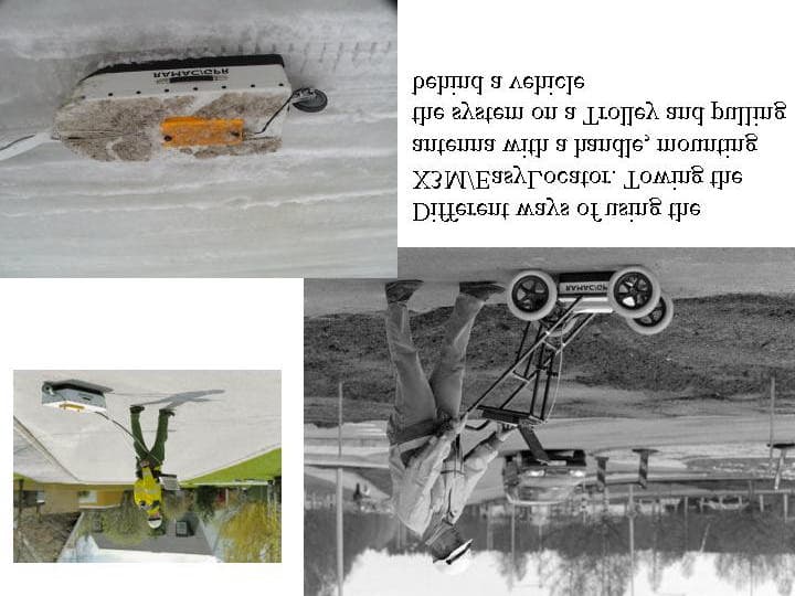
Click to zoom
Application Details
- Equipment Class
- UWB - Ultra Wideband Transmitter
- Date of Grant
- Jan 07, 2003
- Application Purpose
- Original Equipment
- Date of Application
- Sep 02, 2002
- Equipment Note
- Ramac GPR/500 MHz shielded antenna
- Frequency Range
- 195.00000000 - 486.00000000
- Company
- Guideline Geo AB
- Country
- Sweden
Documents & Files
Document Text
Text extracted from the exhibit documents filed with the FCC. Open a document above to read the original.
Users Manual
MALÅ GeoScience RAMAC X3M and EasyLocator Hardware Manual 2 Important note: In the US this unit operates under FCC rules Part 15. According to these rules a GPR system shall contain a manually operated switch that causes the transmitter to cease operation within 10 seconds of being released by the operator. Therefore all units sold after July 15 2002, in the US, will have this functionality and also be delivered with a kill switch. Units sold outside the US will have a plug attached to the kill switch connector. Removing this plug causes the unit to cease functioning. No kill switch will be delivered to destinations outside US. The kill switch and how it’s to be handled is further explained in this manual. 3 Table of Contents ____________________________________________________________ 1. Introduction 3 1.1 Unpacking and Inspection 3 1.2 Repacking and Shipping 3 2. Start up and hardware description 4 2.1 Layout of the X3M 4 2.2 Mounting on the shielded antenna 5 2.3 Power cable 5 2.4 Distance measuring devices 5 2.5 Connection to computer 6 2.6 Kill switch 6 2.7 Start up and power button 7 3. Batteries and charging 8 3.1 Batteries 8 3.2 Charging 8 4. Software 8 5. Using the RAMAC X3M 9 6. RAMAC X3M specifications 10 4 1Introduction ___________________________________________________________ Thank you for purchasing the RAMAC X3M/EasyLocator. We at Mala GeoScience welcome comments from you concerning the use and experience of this equipment, as well as the contents and usefulness of this manual. Please take the time to read through the assembling instructions carefully and address any questions or suggestions to the following: MALÅ GeoScience postal address is: Main Office:Subsidiary: Malå GeoScienceMalå GeoScience USA, Inc. E-Mail: [email protected] Skolgatan 11P.O. Box 80430 [email protected] S-930 70 MalåCharleston, SC 29416 [email protected] SwedenUSA [email protected] Phone: +46 953 345 50Phone: +1-843 852 5021 Fax: +46 953 345 67Fax:+1-843 769 7397 Information about MALÅ Geoscience’s products is also available on Internet: www.malags.com (Be sure to include instrument type and serial numbers) 1.1 Unpacking and Inspection Great care should be taken when unpacking the equipment. Be sure to verify the contents shown on the packing list and inspect the equipment for any loose parts or other damage. All packing material should be preserved in the event that any damage occurred during shipping. Any claims for shipping damage should be filed to the carrier. Any claims for missing equipment or parts should be filed with Mala GeoScience. 1.2 Repacking and Shipping If original packing materials are unavailable, the equipment should be packed with at least 80 mm of absorbing material. Do not use shredded fibers, paper wood, or wool, as these materials tend to get compacted during shipment and permit the instruments to move around inside the package. 5 2 Start up and Hardware Description ___________________________________________________________ The RAMAC X3M/EasyLocator is an integrated radar control unit, mounted directly on the shielded antennas and powered externally. X3M is compatible with the RAMAC/GPR shielded antennas 100, 250, 500 and 800MHz. EasyLocator has it own family of shielded antennas; DEEP, MID and SHALLOW. The built-in electronic design makes it a low weight and compact size system, easier to assemble and operate. No fiber optic cables are required since the unit communicates directly with the laptop. Based on the flexibility and the modularity of the RAMAC/GPR, the RAMAC X3M is fully compatible with the Windows based acquisition software Ground Vision, while the EsayLocator has it own acquisition software: EasyVision. The built-in default autostacking function secures the best data quality at maximum survey speed, in both units. This section will give a short overview of how the GPR (Ground Penetrating Radar) systems work. 2.1Layout of the RAMAC X3M /EasyLocator Figure 2.1a. Layout of the X3M The different number in Figure 2.1 corresponds to the following: 1:Connector for kill switch 2:Power button 3:Connector for encoder, 9 pin d-sub (wheel or hip chain) 4:Connector for parallel cable to a PC, 25 pin d-sub 5:Securing screws for mounting on antennas 6:Power cable connection Figure 2.1. Layout of RAMAC X3M 5. Securing screws 1. Kill switch connection 3. Encoder connection 6. Power cable connection 4. Parallel cable port connection 2. Power button 6 Figure 2.1 b. The same connectors as in figure 2.1a showed on an EasyLocator. 2.2Mounting on the shielded antennas Start by placing the X3M/EasyLocator on the antenna that you are going to use for your measurement. The Parallel port and the Power connection should point forward according to the picture (Figure 2.2). Fasten the unit on the antenna by tighten the securing screws. Figure 2.2 Mounting on the antenna 3. Encoder 6. DC power 4. PC comm. 1. Kill switch 2. ON/OFF 7 2.3Power cable When the X3M/EasyLocator is mounted on the antenna connect the Power cable from your battery. Look for the countersink and place it towards the mark on the connection. Push lightly. If you have it in the correct position it should connect smoothly. To disconnect: Pull out, holding the milled part of the connection. 2.4 Distance measuring devices The X3M/EasyLocator can be used together with the standard MALÅ GeoScience distance measuring devices (hip-chain and measuring wheels). The encoder cable is connected as shown below (Figure 2.4) 2.5Connection to computer Add the computer to the system by connecting the parallel port cable between the computer and the X3M/EasyLocator (Figure 2.5). Use an IEEE 1284 compatible parallel cable that is less than or equal to three meters long. Figure 2.4. Encoder Figure 2.3. Power cable Figure 2.5. Parallel port 8 2.6 Kill switch The kill switch is attached to a handle that can either be handheld or snapped onto a RAMAC/GPR Cart (Figure 2.6 top). The X3M/EasyLocator will not be operational without the kill switch.…
Text truncated - open the document above for the full version.
Cover Letter(s)
September 3, 2002 C OVER L ETTER Re: Malå GeoScience AB, application for Ground Penetrating Radar FCC ID: QLA500MHZ Dear Sirs, This application is for the product; Ramac/GPR 500 MHz shielded antenna, designed to operate with the Ramac/GPR X3M unit for witch an application has been filed FCC ID: QLAX3MEASYLOCATOR Best regards Bernth Johansson Head R&D Malå GeoScience Skol gata n 11 S-930 70 Malå Sweden
External Photos
1 External photos of Ramac/GPR X3M and EasyLocator units and antennas. Figure 1. An X3M unit. An EasyLocator has identical connectors but different colour and label. 2 Figure 2. EasyLocator mounted on “EasyLocator MID” antenna. The whole system incl. PC mounted on a trolley. Figure 3. Kill switch to be connected to the X3M/EasyLocator units 3 Figure 4. Overview of antenna connectors located on the bottom side of the X3M/EasyLocator and topside of antennas. 4 Figure 5. A 250MHz shielded antenna 5 Figure 6. 500MHz shielded antenna 6 Figure 7. 800MHz shielded antenna 7 Figure 8. Top view of EasyLocator MID antenna and bottom of the EasyLocator unit, showing the d-sub connectors. 8 Figure 9. EasyLocator MID antenna with wheel attached. 9 Figure 10. Different ways of using the system.
ID Label/Location Info
ID Label/Location info This document contains a figure showing the label in readable format and three photos. The first photo shows an X3M/EasyLocator together with an antenna for orientation. The next two photos show, in detail, where the labels are going to be placed. Figure 1. Label. 90mm 40mm Figure 2. Photo showing the bottom side of the X3M/EasyLocator and the top metal plate of one antenna. This top plate is identical on all shielded antennas. Figure 3. Placement of the FCC label on top metal plate on the shielded antennas and on the bottom side of the X3M/EasyLocator .
ID Label/Location Info
Corrected ID Label/Location info This document contains a figure showing the label in readable format and two photos. The first photo shows an X3M/EasyLocator together with an antenna for orientation. The next photo show, in detail, where the labels are going to be placed. Figure 1. Label. 90mm 40mm Figure 2. Photo showing the bottom side of the X3M/EasyLocator and the top metal plate of one antenna. This top plate is identical on all shielded antennas. Figure 3. Placement of the FCC label on top metal plate on the shielded 500MHz antenna
ID Label/Location Info
ID Label/Location info: QLA500MHZ Figure 1. Label. Figure 2. Placement of the FCC label on top-front of the UWB-unit, visible all times. 60mm 36mm
Test Report
AerotechTelub AB Box 360 831 25 Östersund Besöksadress: Storlienvägen 56 Telefon: 063-15 60 00 Fax: 063-15 61 99 Huvudkontor 732 81 Arboga Telefon: 0589-800 00 Fax: 0589-61 16 52 Org. nr: 556218-6790 Styrelsens säte: Arboga Överföring av dokument i elektronisk form Detta dokument är en elektronisk kopia. Vid konvertering eller överföring i elektronisk form kan dokumentet bli förvanskat. Det fastställda pappersoriginalet är det gällande dokumentet. Transfer of document in electronic form This document is an electronic copy of the original. When converting or transferring the document into electronic form, it could be distorted. The original paper document is to be considered the valid document. AerotechTelub AB Box 360. S-831 25 Östersund, Sweden. Visitors: Storlienvägen 56. Telephone: +46 63 15 61 00. Telefax: +46 63 15 61 99 Internal Ref No 91170-71145 Distribution Malå Geoscience AB Bernt Johansson Skolgatan 11 93070 Malå Copy FB/archive, FBM/archive Document Test Report Date September 3, 2002 Prepared FBM, Henrik Olsson EMC Test Engineer Ref. No E014-TR 020125 Supersedes Page 1 (10) Title EMC Test, Shielded 500 MHz antenna Equipment under test (EUT): Description: Active antenna for Ground Penetrating Radar System Manufacturer: Malå Geoscience Model name: Shielded 500 MHz Summary: The EUT complied with the requirement of radiated emissions given in FCC 15.209, measured in the frequency range 30 – 960 MHz Approved: Petter Gärdin Ass. Laboratory Technical Manager Ref No E014-TR 020125 Page 2(10) AerotechTelub AB Contents 1 Introduction .................................................................................................................3 2 Test methods and results ............................................................................................. 3 2.1 Results ............................................................................................................. 3 3 Applicable documents ................................................................................................. 3 4 Equipment under test (EUT) ....................................................................................... 4 4.1 Identification of equipment under test ............................................................ 4 4.2 Test site ........................................................................................................... 4 4.3 General configuration of EUT ........................................................................ 5 4.4 Operation of EUT during tests ........................................................................ 5 5 Emission ......................................................................................................................6 5.1 Measurement of radiated emission, ANSI C63.4............................................ 6 Ref No E014-TR 020125 Page 3(10) AerotechTelub AB 1 Introduction The object of the test is to show compliance with the emission standard FCC Part 15. Date of test: August 13, 2002 Location: Malå Geoscience, Malå Sweden Test performed by: Henrik Olsson, AerotechTelub / FBM Client: Malå Geoscience Skolgatan 11 SE-93070 Malå Sweden Client’s observers: Lars Lundmark, Malå Geoscience Bernt Johansson, Malå Geoscience 2 Test methods and results 2.1 Results The test results in this report apply only for the tested specimen. EMISSION REQUIREMENTS ACCORDING TO FCC 15.209 Environmental phenomena Test method Requirement Result Comments Test order Radiated emission ANSI C63.4 FCC 15.209 Pass 1 3 Applicable documents Measurements ANSI C63.4 1992-07-17 Radio noise emissions from low-voltage electrical and electronic equipment in the range of 9 kHz to 40 GHz. FCC Part 15 2002-07-22 Radio Frequency Devices FCC 02-42 2002-04-22 Revision of Part 15 of the Commission’s Rules Regarding Ultra- Wideband Transmission Systems Ref No E014-TR 020125 Page 4(10) AerotechTelub AB 4 Equipment under test (EUT) 4.1 Identification of equipment under test Equipment under test (EUT): Description: Active antenna for Ground Penetrating Radar System Manufacturer: Malå Geoscience Model name: Shielded 500 MHz Serial No: 006386 Build state: Production sample 4.2 Test site 4.2.1 Description The test site was located outside the Malå Geoscience’s facilities in Malå at about 50 m distance from the nearest building. According to the measurement procedures 51 cm (20”) of dry sand was placed in the ground, under the EUT. A ground plane, made by sheet metal, was formed around the EUT and protruding under the measurement antenna. The EUT was placed directly on the dry sand with no ground plane under it. Picture 1: Test Site The measurement distance antenna – EUT was 3 m. The measurement system and related equipment were placed in a van located 15 m behind the antenna. Ref No E014-TR 020125 Page 5(10) AerotechTelub AB 4.2.2 Ambient signals Mobile telephones: 460 – 470 MHz, 937 – 945 MHz FM broadcasts: 89 – 102 MHz Television: 174 – 181 MHz, 216 – 224 MHz, 494 – 501 MHz In addition many signals of short-term duration were found. Each measurement signal close to or above the limit was examined if ambient or related to the EUT. 4.3 General configuration of EUT The EUT was powered by its internal battery pack. The EUT was connected to a Malå Geoscience Control Unit CU II via fibre optic cables. The CU II was placed beside the test site, not being a subject of the test. No other cables were connected to the EUT or the Control Unit. No more connectors were provided on the EUT. 4.4 Operation of EUT during tests The Control Unit was gathering data from the EUT like in normal operation. Ref No E014-TR 020125 Page 6(10) AerotechTelub AB 5 Emission 5.1 Measurement of radiated emission, ANSI C63.4 5.1.1 Requirements according to FCC 15.209 Radiated emission from the EUT in the frequency range 30 to 960 MHz shall not exceed the limit as specified below. Frequency range Limit 30 - 88 MHz 40 dBμV/m 88 – 216 MHz 43.5 dBμV/m 216 – 960 MHz 46 dBμV/m 5.1.2 Procedures The r…
Text truncated - open the document above for the full version.
Test Report
AerotechTelub AB Box 360 831 25 Östersund Besöksadress: Storlienvägen 56 Telefon: 063-15 60 00 Fax: 063-15 61 99 Huvudkontor 732 81 Arboga Telefon: 0589-800 00 Fax: 0589-61 16 52 Org. nr: 556218-6790 Styrelsens säte: Arboga Överföring av dokument i elektronisk form Detta dokument är en elektronisk kopia. Vid konvertering eller överföring i elektronisk form kan dokumentet bli förvanskat. Det fastställda pappersoriginalet är det gällande dokumentet. Transfer of document in electronic form This document is an electronic copy of the original. When converting or transferring the document into electronic form, it could be distorted. The original paper document is to be considered the valid document. Distribution Malå Geoscience AB Bernth Johansson Skolgatan 11 93070 Malå, SWEDEN Copy FB/archive, FBM/archive Document Test Report Date December 18, 2002 Prepared FBM, Petter Gärdin EMC Test Engineer Ref. No E014-TR 020223 Supersedes Page 1 (18) Title EMC Test, 500 MHz Shielded antenna Equipment under test (EUT): Description: Ground Penetrating Radar System Manufacturer: Malå Geoscience Model name: 500 MHz Shielded antenna Summary: With modifications described in 4.5 the EUT complied with the requirement of radiated emissions given in FCC Part 15 Subpart F, measured in the frequency range 30 – 5000 MHz. Approved: Per Larsson Ass. Laboratory Technical Manager AerotechTelub AB Box 360. S-831 25 Östersund, Sweden. Visitors: Storlienvägen 56. Telephone: +46 63 15 61 00. Telefax: +46 63 15 61 99 Internal Ref No 91170-71145 Ref No E014-TR 020223 Page 2(18) Contents 1 Introduction..................................................................................................................3 2 Test methods and results..............................................................................................3 2.1 Results.............................................................................................................3 3 Applicable documents..................................................................................................4 4 Equipment under test (EUT)........................................................................................5 4.1 Identification of equipment under test.............................................................5 4.2 Test site............................................................................................................5 4.3 General configuration of EUT.........................................................................6 4.4 Operation of EUT during tests.........................................................................6 4.5 Modifications...................................................................................................7 5 Emission.......................................................................................................................8 5.1 Measurement of radiated emission, ANSI C63.4............................................8 5.2 Measurement of radiated emission................................................................10 5.3 Measurement of UWB bandwidth and peak emissions.................................15 AerotechTelub AB Ref No E014-TR 020223 Page 3(18) 1 Introduction The object of the test is to show compliance with the emission requirements of FCC Part 15 Subpart F. Date of test: December 10-11, 2002 Location: AerotechTelub AB, Östersund Test performed by: Petter Gärdin, AerotechTelub / FBM Client: Malå Geoscience Skolgatan 11 SE-93070 Malå Sweden Client’s observers: Lars Lundmark, Malå Geoscience 2 Test methods and results 2.1 Results The test results in this report apply only for the tested specimen. EMISSION REQUIREMENTS ACCORDING TO FCC Part 15 Subpart F Environmental phenomena Test method Requirement Result Comments Test order Radiated emission ANSI C63.4 FCC 15.209 PASS 3 UWB definition FCC 15.503 (a) 15.509(a) PASS f L 195 f C 340 f H 4861 Peak emission at f M FCC 02-42 FCC 15.509 (f) PASS 2 Radiated emission FCC 02-42 FCC 15.509 (d) PASS 4 Radiated emission FCC 02-42 FCC 15.509 (e) PASS 5 AerotechTelub AB Ref No E014-TR 020223 Page 4(18) 3 Applicable documents Measurements ANSI C63.4 1992-07-17 Radio noise emissions from low-voltage electrical and electronic equipment in the range of 9 kHz to 40 GHz. FCC Part 15 2002-07-22 Radio Frequency Devices FCC 02-42 2002-04-22 Revision of Part 15 of the Commission’s Rules Regarding Ultra- Wideband Transmission Systems AerotechTelub AB Ref No E014-TR 020223 Page 5(18) 4 Equipment under test (EUT) 4.1 Identification of equipment under test Equipment under test (EUT): Description: Ground Penetrating Radar System. Manufacturer: Malå Geoscience Model name: 500 MHz Shielded antenna. Build state: Production sample Serial no: 6386 4.2 Test site 4.2.1 Description The measurements were all performed on a weather protected open area test site that was modified with a flat sand bed located in the ground plane. The sand bed is about 50 cm deep. Picture 1: Test Site The measurement distance antenna – EUT was 1 and 3 m. The measurement system and related equipment were placed next to the test site. AerotechTelub AB Ref No E014-TR 020223 Page 6(18) 4.2.2 Ambient signals A number of ambient signals were detected in the different frequency ranges measurement was made; some of those are listed below. Mobile telephones: 460 – 470 MHz, 937 – 945 MHz, 1.8 GHz FM broadcasts: 87 – 108 MHz Television: 60 – 70 MHz, 650 – 800 MHz Radar system: 1.3 GHz In addition many signals of short-term duration were found. Each measurement signal close to or above the limit was examined if ambient or related to the EUT. 4.3 General configuration of EUT A battery powered the EUT. The EUT was connected with the control unit with a fiber optical cable. The EUT was placed directly on the dry sand with no ground plane under it. Picture 2: EUT setup on sand bed 4.4 Operation of EUT during tests The EUT was gathering data like in normal operation. AerotechTelub AB Ref No E014-TR 0…
Text truncated - open the document above for the full version.
Contact Information
Applicant
Johan Friborg(Research lead GPR)
Test Firm
Aerotech Telub ABPetter Gardin
Technical Specifications
| # | Rule Parts | Frequency Range | Power Output |
|---|---|---|---|
| 1 | 15F | 195 MHz - 486 MHz | - |
Other Applications from Guideline Geo AB

QLA-MIRAHDR500
Apr 15, 2020GPR Array System
Equipment Class
UWB - Ultra Wideband Transmitter
QLA450MHZHDR
May 17, 2014Ground Penetrating Radar
Equipment Class
UWB - Ultra Wideband Transmitter
QLA160MHZHDR
Jan 23, 2014Ground Penetrating Radar
Equipment Class
UWB - Ultra Wideband Transmitter
QLA750MHZHDR
Jan 23, 2014Ground Penetrating Radar
Equipment Class
UWB - Ultra Wideband Transmitter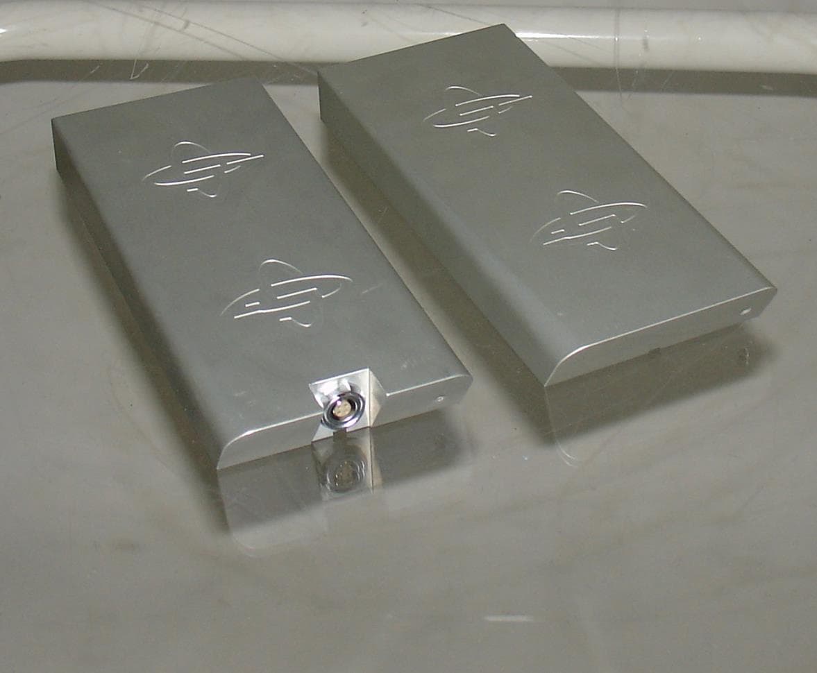
QLA80MHZHDR
Jan 23, 2014Ground Penetrating Radar
Equipment Class
UWB - Ultra Wideband Transmitter