QLA800MHZ
Guideline Geo AB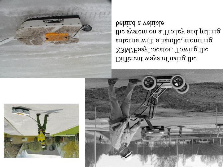
Click to zoom
Application Details
- Equipment Class
- UWB - Ultra Wideband Transmitter
- Date of Grant
- Oct 22, 2003
- Application Purpose
- Original Equipment
- Date of Application
- Sep 02, 2002
- Frequency Range
- 144.00000000 - 1570.00000000
- Company
- Guideline Geo AB
- Country
- Sweden
Documents & Files
Document Text
Text extracted from the exhibit documents filed with the FCC. Open a document above to read the original.
Users Manual
MALÅ GeoScience RAMAC X3M and EasyLocator Hardware Manual 2 Important note: In the US this unit operates under FCC rules Part 15. According to these rules a GPR system shall contain a manually operated switch that causes the transmitter to cease operation within 10 seconds of being released by the operator. Therefore all units sold after July 15 2002, in the US, will have this functionality and also be delivered with a kill switch. Units sold outside the US will have a plug attached to the kill switch connector. Removing this plug causes the unit to cease functioning. No kill switch will be delivered to destinations outside US. The kill switch and how it’s to be handled is further explained in this manual. 3 Table of Contents ____________________________________________________________ 1. Introduction 3 1.1 Unpacking and Inspection 3 1.2 Repacking and Shipping 3 2. Start up and hardware description 4 2.1 Layout of the X3M 4 2.2 Mounting on the shielded antenna 5 2.3 Power cable 5 2.4 Distance measuring devices 5 2.5 Connection to computer 6 2.6 Kill switch 6 2.7 Start up and power button 7 3. Batteries and charging 8 3.1 Batteries 8 3.2 Charging 8 4. Software 8 5. Using the RAMAC X3M 9 6. RAMAC X3M specifications 10 4 1Introduction ___________________________________________________________ Thank you for purchasing the RAMAC X3M/EasyLocator. We at Mala GeoScience welcome comments from you concerning the use and experience of this equipment, as well as the contents and usefulness of this manual. Please take the time to read through the assembling instructions carefully and address any questions or suggestions to the following: MALÅ GeoScience postal address is: Main Office:Subsidiary: Malå GeoScienceMalå GeoScience USA, Inc. E-Mail: [email protected] Skolgatan 11P.O. Box 80430 [email protected] S-930 70 MalåCharleston, SC 29416 [email protected] SwedenUSA [email protected] Phone: +46 953 345 50Phone: +1-843 852 5021 Fax: +46 953 345 67Fax:+1-843 769 7397 Information about MALÅ Geoscience’s products is also available on Internet: www.malags.com (Be sure to include instrument type and serial numbers) 1.1 Unpacking and Inspection Great care should be taken when unpacking the equipment. Be sure to verify the contents shown on the packing list and inspect the equipment for any loose parts or other damage. All packing material should be preserved in the event that any damage occurred during shipping. Any claims for shipping damage should be filed to the carrier. Any claims for missing equipment or parts should be filed with Mala GeoScience. 1.2 Repacking and Shipping If original packing materials are unavailable, the equipment should be packed with at least 80 mm of absorbing material. Do not use shredded fibers, paper wood, or wool, as these materials tend to get compacted during shipment and permit the instruments to move around inside the package. 5 2 Start up and Hardware Description ___________________________________________________________ The RAMAC X3M/EasyLocator is an integrated radar control unit, mounted directly on the shielded antennas and powered externally. X3M is compatible with the RAMAC/GPR shielded antennas 100, 250, 500 and 800MHz. EasyLocator has it own family of shielded antennas; DEEP, MID and SHALLOW. The built-in electronic design makes it a low weight and compact size system, easier to assemble and operate. No fiber optic cables are required since the unit communicates directly with the laptop. Based on the flexibility and the modularity of the RAMAC/GPR, the RAMAC X3M is fully compatible with the Windows based acquisition software Ground Vision, while the EsayLocator has it own acquisition software: EasyVision. The built-in default autostacking function secures the best data quality at maximum survey speed, in both units. This section will give a short overview of how the GPR (Ground Penetrating Radar) systems work. 2.1Layout of the RAMAC X3M /EasyLocator Figure 2.1a. Layout of the X3M The different number in Figure 2.1 corresponds to the following: 1:Connector for kill switch 2:Power button 3:Connector for encoder, 9 pin d-sub (wheel or hip chain) 4:Connector for parallel cable to a PC, 25 pin d-sub 5:Securing screws for mounting on antennas 6:Power cable connection Figure 2.1. Layout of RAMAC X3M 5. Securing screws 1. Kill switch connection 3. Encoder connection 6. Power cable connection 4. Parallel cable port connection 2. Power button 6 Figure 2.1 b. The same connectors as in figure 2.1a showed on an EasyLocator. 2.2Mounting on the shielded antennas Start by placing the X3M/EasyLocator on the antenna that you are going to use for your measurement. The Parallel port and the Power connection should point forward according to the picture (Figure 2.2). Fasten the unit on the antenna by tighten the securing screws. Figure 2.2 Mounting on the antenna 3. Encoder 6. DC power 4. PC comm. 1. Kill switch 2. ON/OFF 7 2.3Power cable When the X3M/EasyLocator is mounted on the antenna connect the Power cable from your battery. Look for the countersink and place it towards the mark on the connection. Push lightly. If you have it in the correct position it should connect smoothly. To disconnect: Pull out, holding the milled part of the connection. 2.4 Distance measuring devices The X3M/EasyLocator can be used together with the standard MALÅ GeoScience distance measuring devices (hip-chain and measuring wheels). The encoder cable is connected as shown below (Figure 2.4) 2.5Connection to computer Add the computer to the system by connecting the parallel port cable between the computer and the X3M/EasyLocator (Figure 2.5). Use an IEEE 1284 compatible parallel cable that is less than or equal to three meters long. Figure 2.4. Encoder Figure 2.3. Power cable Figure 2.5. Parallel port 8 2.6 Kill switch The kill switch is attached to a handle that can either be handheld or snapped onto a RAMAC/GPR Cart (Figure 2.6 top). The X3M/EasyLocator will not be operational without the kill switch.…
Text truncated - open the document above for the full version.
Cover Letter(s)
September 3, 2002 C OVER L ETTER Re: Malå GeoScience AB, application for Ground Penetrating Radar FCC ID: QLA800MHZ Dear Sirs, This application is for the product; Ramac/GPR 800 MHz shielded antenna, designed to operate with the Ramac/GPR X3M unit for witch an application has been filed FCC ID: QLAX3MEASYLOCATOR Best regards Bernth Johansson Head R&D Malå GeoScience Skol gata n 11 S-930 70 Malå Sweden
Cover Letter(s)
Re:FCC ID QLA800MHZ Applicant: Mala GeoScience AB (publ) Correspondence Reference Number: 24222 731 Confirmation Number: EA813498 Answers in bold. 1) You have requested confidentiality for the Test Report and internal photo's. This is not permitted. Please submit a new letter requesting confidentiality with the Test Report and internal photo's removed. Our lawyer is preparing a letter to Ed Thomas and Bruce Romano explaining why we believe the interior photographs are entitled to confidentiality protection. Please continue processing the application while we attempt to resolve this issue! If the issue has not been decided when you are prepared to grant the certification, then we will either drop the request for confidentiality or ask you to postpone the grant for a short time. If you cannot continue processing while we work on the confidentiality issue, please let me know. 2) The kill switch uses a standard BNC connector which can be easily defeated with a shorted connector. Explain what provisions are being taken to ensure that the provisions of Part 15.509(c) are compliant at all times. Also, how is the kill switch implemented when the device is dragged on the ground while being pulled by a car. Since we did not find any specifications on this device in the report and order nor in the latest part 15, we asked you what the requirements really are. Up to this date we’ve got no answer to this question. Part 15.509(c) is compliant at all time since removing or releasing the switch will cause the UWB-device to cease transmitting, immediately. If the operator wants to tow the unit behind a car he needs to order a kill switch with sufficient cable length. 3) It appears from the photo of the test setup (Picture 2) that the testing was not done in accordance with the measurement procedure of FCC 02-48 Appendix F. The ground plane covers the bed of sand. This is not permitted. Retest as necessary. The guideline requires that the device is tested under conditions of actual operating conditions. e.g. GPR's tested on floor in a bed of sand. Statement from our test lab: ”It is stated in the test report under test site description point 4.2.1 that there is NO ground plane under the EUT. This is a direct copy from the test report text "A ground plane, made by sheet metal, was formed around the EUT and protruding under the measurement antenna. The EUT was placed directly on the dry sand with no ground plane under it." The picture 2 photo shows the ground plane metal sheets formed around the EUT.” 4) Upload an exhibit demonstrating how this device meets the definition of an UWB device as specified in Part 15.503(d) of the Rules. What are the -10 dB points as required by Part 15.503(a) of the Rules? Upload a plot and data for determining the -10 dB points. Include a test procedure. In determining the -10 dB points adjust for non-linearities in the measurement system (antenna factor and preamp gain). The emission should be maximized across the band of operation. The EUT should be rotated, the antenna height should be varied as well as the antenna polarization. We have been requiring that these bandwidth plots be of the electronic signature of the device based on the maximum radiated field strength in 1 MHz RBW from the device at each frequency when using the same detector function(preferably peak) and measured from any direction when operating the device under conditions of actual operating conditions. An answer to this request is being prepared by our test lab and will be uploaded to your web soon. 5) What is the center frequency of this device? Show calculation. An answer to this request is being prepared by our test lab and will be uploaded to your web soon. 6) The Test Report indicates that radiated emissions were tested up to 960 MHz. There is no data for frequencies > 960 MHz. Upload data showing compliance with the limits of 15.509(d) of the Rules for frequencies up to 5 GHz. If there are no observable emissions, the noise floor of the measurement must be reported. This will require a pre-amplifier. Include the pre- amplifier calibration information (gain, calibration date, etc.) in the exhibit. Use the procedure of Part 15.521. For RMS average field strength measurements refer to the procedure in Appendix F. All RMS measurements should include a procedure and data as necessary. Provide the test procedure used including description on maximizing emissions and EUT configuration. Also provide test setup photos. An answer to this request is being prepared by our test lab and will be uploaded to your web soon. 7) Submit an exhibit showing compliance with the 50 MHz BW requirements of Part 15.509(f) of the Rules. Ensure that this is performed at the frequency containing the highest field strength. An answer to this request is being prepared by our test lab and will be uploaded to your web soon. 8) Upload a photo and location diagram showing compliance with the labeling requirements of Part 15.509(g) of the Rules. In addition, the labeling per 15.19 is not in a conspicuous location. It appears that it is in a location that is sandwiched between the antenna and to plate. Please correct. Sorry, I used the wrong wording. A new document defining the label as well as its location on the UWB-unit has been uploaded with the description field filled in as “New label and location”. 9) What is the pulse width of this device. Is the pulse random (dithered) or periodic? Upload an exhibit with the pulse characteristics of this device. Include a plot. The 800 MHz antenna/UWB-unit has a pulse width of about 1.1ns, in air. A plot of the pulse is shown in figure 1 below. The pulse is periodic with a repetition frequency of 100 kHz. Figure 1. Pulse characteristic of a 800 UWB-unit. 10) What measures have been taken to ensure that the emissions from the top of the device are less than the ground penetrating emissions. It is recommended that a field strength measurement be done directly above the device to show compliance w…
Text truncated - open the document above for the full version.
Cover Letter(s)
Malå 2002-11-11 Re: Ways to open up Mala UWB-equipment We were asked to let our lab describe how our UWB-units are mechanically designed and how they could be opened, in order to view the breadboards inside. Our test lab refuses to do such work! Their arguments: 1) The units cannot be opened up without causing damage. 2) As a test lab they verify whether certain equipment, with a model and serial number, complies with a specified regulation. They do not have the means nor the will to start opening up and examining equipment. In their view this is something that the manufacturer has to be responsible for. Our contact person at the lab is Petter Gärdin, as specified in our 731 form. Since this document might also be part of what FCC publish, I’m giving a short version of the mechanical design below: - The units 250, 500 and 800MHz and EasyLocator MID all have their covers fastened by means of rivets and/or one-way screws. - The antenna flares are attached to the surrounding rf-absorbers and shields by means of glued material. This material will be damaged during disassembly. - Metal shielding is surrounding each antenna flare on all sides except the bottom side, which in normal operation faces ground. - In order to view all breadboards all shields and absorbers has to be removed and breadboards de-soldered. - Disassembly of the units, by a customer or competitor, is likely to cause permanent damage of the unit. - Malå does not inform customers of how to open up the units nor do we repair units that have been tampered with, in theses cases new units will be shipped and charged for. Bernth Johansson Head R&D Malå GeoScience
Cover Letter(s)
Malå 2002-11-14 Re: Pending applications: QLA250MHZ EA586775 QLAMID EA364767 QLA500MHZ EA369105 QLA800MHZ EA813498 Rules parts for these applications were wrongly specified as 15C during filing. Correct rule parts for all the applications above should be 15F Best regards Bernth Johansson Head R&D Malå GeoScience
Cover Letter(s)
Östersund 2002-12-19 Re: Pending applications: Re: FCC ID QLA800MHZ Applicant: Mala GeoScience AB (publ) Correspondence Reference Number: 24310 731 Confirmation Number: EA813498 New test report TR020224 SA 800.pdf is uploaded to your site. Best regards Petter Gärdin Senior EMC engineer AerotechTelub AB
Cover Letter(s)
Re: FCC ID QLA800MHZ Applicant: Mala GeoScience AB (publ) Correspondence Reference Number: 24650 731 Confirmation Number: EA813498 Dear Sirs, 1) Please provide photo's of the modifications made to the device. Submit the photo's as a separate document so that they can be held confidential. New internal photos has been uploaded to your web site. 2) Indicate the frequency range of radiated measurements for the UWB bandwidth test. Plots were only submitted to 1 GHz. See uploaded document from our test lab. (SA800 email...) 3) Provide data table for QP measurements below 960 MHz. Report data per C63.4 Section 10.1.8.2, please submit the highest emission of the fundamental with the frequency and the frequency and level of the three highest emissions relative to the limit. See uploaded document from our test lab. (SA800 email...) 4) Verify that both labeling requirements of 15.509(g) and 15.19 will be placed on the device. We were not avare of this! For the uwb-units that we’ve got granted so far we did not have to put two labels on the devices. Please verify that no misstakes has been made and we will put both labels on the unit. 5) Verify that the new frequency range is 540-935 MHz. See uploaded document from our test lab.(SA800 email...)
Cover Letter(s)
Answers to your questions are inserted in the email below. To: Petter Gardin, From: Joe Dichoso [email protected] FCC Application Processing Branch Re: FCC ID QLA800MHZ Applicant: Mala GeoScience AB (publ) Correspondence Reference Number: 24649 731 Confirmation Number: EA813498 2) Indicate the frequency range of radiated measurements for the UWB bandwidth test. Plots were only submitted to 1 GHz. Plots indicate that the UWB bandwidth test was performed to from 30 MHz to 1 GHz. There is no demand in the FCC documents to do additional measurements to verify the definitions according to 15.503 (a-d) and 15.509 (a). Measurements to show compliance with 15.509 (d) have been performed up to 5 GHz. 3) Provide data table for QP measurements below 960 MHz. Report data per C63.4 Section 10.1.8.2, please submit the highest emission of the fundamental with the frequency and the frequency and level of the three highest emissions relative to the limit. Frequency Amplitude Antenna polarization Delta to quasi peak limit *) 840 35.2 quasi peak Vertical -10.8 720 39 peak Vertical -7 920 37 peak Vertical -9 600 37 peak Vertical -9 300 31 peak Vertical -15 205 29 peak Vertical -14.5 *) Negative value means below limit 5) Verify that the new frequency range is 540-935 MHz. The results of the UWB bandwidth test are described in point 5.3.3 in the test report.
Cover Letter(s)
Re: FCC ID QLA800MHZ > Applicant: Mala > GeoScience AB (publ) > Correspondence Reference Number: 25692 > 731 Confirmation Number: EA813498 > > > 1) A Photo of modification 1 was submitted on > 1/22/03 and modification 2 was submitted on > 6/25/03. The last reply indicates that modification > 3 in Section 4.5 of the new test report is the only > modification that will be made. Please verify that > I can delete modification 1 and modification 2. > Also, provide a photo of modification 3. Yes you can delete modification 1 and 2. A new document with modification 3 has been uploaded on your web. > > 2) For the UWB test, please provide the peak > measurement data for Fl(144 MHz), Fh(1.570 GHz) > and, Fm(820 MHz) at 1 MHz. Please indicate what > test distance these measurements were. This is > needed to verify UWB frequency range and the peak > level(fm). The UWB bandwidth is taken from the 10 > dB points that are the furthest from the peak emission(fm). Statement from our test lab ” Fl=35 dBμV/m, 3 meter measurement distance Fm=45 dBμV/m, 3 meter measurement distance Fh=25 dBμV/m, 1 meter measurement distance recalculated for 3 meter distance As the measurement properties are different below and above 960 MHz the Fh frequency have been estimated from the maximum background level at 960 MHz at the two measurements. ” > 3) The peak measurement must be corrected to 50 > Mhz. Please indicate what distance this test was > made. Please make appropriate corrections to > compare to limit at the proper distance. Statement from our lab ” According to point 15.521 in the standard the peak emission limit shall be corrected to the measurement bandwidh used, due to this fact the peak level was not corrected to 50 MHz bandwith but the limit for the peak level was corrected to the measurement bandwith used (1 MHz) as can be seen in the testreport point 5.3.3. The measurement distance at Fm was 3 meters. ” > 4) Please indicate whether the EUT was kept within > the boresite of the receiving antenna during all > measurements. Specifically, was the receiving > antenna adjusted to keep the EUT within the > boresite of the receiving antenna when the antenna > was raised to maximize emissions? Statement from our lab: ”YES” > 5) The confidentiality request includes the test > report and internal photo's. These items cannot > be held confidential. Please remove them from the > list and submit a new confidential request letter. In a letter dated November 7, 2002 our lawyer motivated our confidentiality request, for four pending applications, including this. FCC accepted this and I’ve got a written respond for all applications except this one. So, either have I dropped the letter somewhere or FCC didn’t send me a letter. We are in any case seeking confidentiality for the same items as before and on the same grounds as before. The other applications I’m referring to are (FCC ID): QLA250MHZ QLAMID QLA500MHZ Best regards Bernth Johansson
Cover Letter(s)
Re: FCC ID QLA800MHZ Applicant: Mala GeoScience AB (publ) Correspondence Reference Number: 25746 731 Confirmation Number: EA813498 Dear sirs, Your questions in cursive text and answers in normal. 1) With regard to the UWB bandwidth test, you must use the same measurement detector and spectrum analyzer settings to determine the proper bandwidth. We recommend using a peak detector and a 1 MHz RBW across the entire bandwidth regardless of whether the part of the emission is below 960 MHz or not. In your last reply regarding the UWB bandwidth test you performed you indicated that_. "As the measurement properties are different below and above 960 MHz the Fh frequency have been estimated from the maximum background level at 960 MHz at the two measurements." Please explain what detector and analyzer settings were used. If you used different measurement settings below and above 960 MHz, you must redo the UWB bandwidth test to ensure that the same detector and settings were used across the entire emission. Statement from our test lab ”The same spectrum analyzer setting (peak detector, 1MHz RBW) was used during the measurements above and below 960 MHz, the only difference was the measurement distance and antenna, but that was compensated for to get comparable field strength levels. ” 2) The confidentiality request includes the test report and internal photo's. Please provide the written response allowing both items to be held confidential. You need to obtain this and submit it or revise the confidentiality request removing these items. We will once again contact our lawyer and ask him to handle this case once again for us.
Cover Letter(s)
Fletcher, Heald & Hildreth, P.L.C. 1300 North 17 th Street 11 th floor Arlington VA 22209 703-812-0400 (voice) 703-812-0486 (fax) MITCHELL LAZARUS 703-812-0440 [email protected] November 7, 2002 Mr. Edmond J. Thomas Chief, Office of Engineering and Technology Federal Communications Commission 445 12th Street SW Washington DC 20554 Re:Certification Applications: Mala GeoScience AB FCC ID QLA250MHZEA586775 FCC ID QLAMIDEA364767 FCC ID QLA500MHZEA369105 FCC ID QLA800MHZEA813498 Dear Mr. Thomas: The above-referenced applications, filed by Mala GeoScience AB, seek certifications for ground-penetrating radar (GPR) devices. The applications show compliance with the Commission's Rules and do not require waivers. Request for Confidentiality The applicant made timely requests under Section 0.459 that certain photographs showing the interior of the devices be withheld from public disclosure. FCC Response FCC laboratory personnel informed the applicant that confidential treatment of the internal photographs is not permitted. Factual Basis for Confidentiality Request Ordinarily the Commission denies confidentiality to photographs of a device on the ground that the information they contain is freely available to a competitor, simply by purchasing the device and (if necessary) unscrewing the cover. Mr. Edmond J. Thomas November 7, 2002 Page 2 But the devices in question are different. The interior is sealed, and its appearance is inaccessible to the purchaser. The device is intentionally made difficult to open. To gain access to the views shown the interior photographs, a competitor would have to purchase the device and then carry out the following steps: 1.Use a drill to dismantle all the rivets securing the cover. A competitor has no way of knowing the correct drill size, or where to begin dismantling. Use of the wrong drill, or starting with the wrong rivets, will require replacing all mechanical parts. 2.Destroy the loading of both the transmitter and receiver. Absorbers are glued to the transmitter and receiver elements and cannot be removed undamaged. The antenna flares are connected to the RF absorbers, as well as to the metallic shields with thin layers of absorbers glued in place. These strips cannot be loosened without destroying them. A competitor is unlikely to have access to the right material, or even to know what grade of materials to use. 3.Use a screwdriver to dismantle the shields and the top plate. 4.De-solder the sampler head, so as to remove the electronics. But high- performance, temperature-sensitive Schottky bridges are placed directly at the soldering point connecting the sampler head to the preamp transmission line. Efforts to remove the electronics are thus likely to cause serious damage. Mala Geoscience has never released instructions on how to disassemble its units, and does not answer questions on how to do so. This information is kept internal to the company. If a unit arrives at the company's repair facility showing evidence of such tampering, the company does not repair it, but charges the customer for a new unit plus freight costs. The Commission's posting of the photographs would allow a competitor to bypass this difficult and expensive disassembly. From the photographs, a competitor could estimate: 1.the costs of manufacturing the breadboards and mechanical housing; 2.the man-hours required to assemble the device; Mr. Edmond J. Thomas November 7, 2002 Page 3 1 5 U.S.C. Sec. 552(b)(4). 2 McDonnell Douglas Corp. v. NASA, 180 F.3d 303, 304-05 (D.C. Cir. 1999), quoting Critical Mass Energy Project v. NRC, 975 F.2d 871, 879 (D.C. Cir. 1992) (en banc). 3 Worthington Compressors, Inc., v. Costle, 662 F.2d 45, 51 (D.C. Cir. 1981), citing National Parks & Conservation Ass'n v. Morton, 498 F.2d 765, 770 (D.C.Cir.1974). 4 Id. (italics in original). 3.any compatibility problems the manufacturer will have in designing new systems; and 4.the age of the electronic design (which gives valuable competitive information on upgrade and R&D efforts). The interior photographs required with an application would almost permit a competitor to conduct a complete reverse engineering, to the point of producing a schematic. We submit that manufacturers should not be required to hand over to competitors the fruits of years of expensive engineering. Legal Basis for Request The Freedom of Information Act (FOIA) protects from disclosure "commercial or financial information obtained from a person and privileged or confidential." 1 Information is confidential if it is "the kind of information 'that would customarily not be released to the public by the person from whom it was obtained,'" 2 and would cause "substantial harm to the competitive position of the person from whom the information was obtained." 3 There can be no serious question that the photographs at issue here meet both of these tests. Mala Geoscience does not make public the appearance of the interior of its products; it deliberately makes the interior difficult to access; and it withholds information on disassembly techniques. Disclosure would cause substantial harm by revealing engineering details that are not otherwise available. The D.C. Circuit in Worthington Compressors addressed the specific issue underlying the present request: the "additional wrinkle that the requested information is available, at some cost, from an additional source." 4 Here, of course, the "additional source" is the acquisition and Mr. Edmond J. Thomas November 7, 2002 Page 4 5 Id. (italics in original). 6 Id. 7 Id. 8 Id. 9 Id. (citation footnote omitted). destruction of a specimen unit, and the cost is that of repairing or replacing it following access to the interior. According to the Worthington court, availability of the information through alternate sources triggers two additional inquiries: (1) the commercial value of the information, and (2) the cost of acquiring the information through other means. 5 The court acknowledges that the submitting party ca…
Text truncated - open the document above for the full version.
External Photos
1 External photos of Ramac/GPR X3M and EasyLocator units and antennas. Figure 1. An X3M unit. An EasyLocator has identical connectors but different colour and label. 2 Figure 2. EasyLocator mounted on “EasyLocator MID” antenna. The whole system incl. PC mounted on a trolley. Figure 3. Kill switch to be connected to the X3M/EasyLocator units 3 Figure 4. Overview of antenna connectors located on the bottom side of the X3M/EasyLocator and topside of antennas. 4 Figure 5. A 250MHz shielded antenna 5 Figure 6. 500MHz shielded antenna 6 Figure 7. 800MHz shielded antenna 7 Figure 8. Top view of EasyLocator MID antenna and bottom of the EasyLocator unit, showing the d-sub connectors. 8 Figure 9. EasyLocator MID antenna with wheel attached. 9 Figure 10. Different ways of using the system.
ID Label/Location Info
ID Label/Location info: QLA800MHZ Figure 1. Label 1. Figure 2. Label 2. 60mm 36mm 60mm 36mm Figure 3. Placement of the FCC labels on front of the UWB-unit, visible all times.
Test Report
Distribution Malå Geoscience AB Bernth Johansson Skolgatan 11 93070 Malå, SWEDEN Copy FB/archive, FBM/archive Document Test Report Date 28 August, 2003 Prepared FBM, Henrik Olsson EMC Test Engineer Ref. No E014-TR 030139 Supersedes Page 1 (24) Title EMC Test, 800 MHz Shielded antenna - modified Equipment under test (EUT): Description: Ground Penetrating Radar System Manufacturer: Malå Geoscience Model name: 800 MHz Shielded antenna Summary: With modifications described in 4.5 the EUT complied with the requirement of radiated emissions given in FCC Part 15 Subpart F, measured in the frequency range 30 – 10 000 MHz. Approved: Petter Gärdin Laboratory Technical Manager AerotechTelub AB Box 360. S-831 25 Östersund, Sweden. Visitors: Storlienvägen 56. Telephone: +46 63 15 61 00. Telefax: +46 63 15 61 99 Internal Ref No 91170-71145 Ref No E014-TR 030139 Page 2(24) Contents 1 Introduction..................................................................................................................3 2 Test methods and results..............................................................................................4 2.1 Results....................…
Text truncated - open the document above for the full version.
Contact Information
Applicant
Johan Friborg(Research lead GPR)
Test Firm
Aerotech Telub ABPetter Gardin
Technical Specifications
| # | Rule Parts | Frequency Range | Power Output |
|---|---|---|---|
| 1 | 15C | 144 MHz - 1.57 GHz | - |
Other Applications from Guideline Geo AB

QLA-MIRAHDR500
Apr 15, 2020GPR Array System
Equipment Class
UWB - Ultra Wideband Transmitter
QLA450MHZHDR
May 17, 2014Ground Penetrating Radar
Equipment Class
UWB - Ultra Wideband Transmitter
QLA160MHZHDR
Jan 23, 2014Ground Penetrating Radar
Equipment Class
UWB - Ultra Wideband Transmitter
QLA750MHZHDR
Jan 23, 2014Ground Penetrating Radar
Equipment Class
UWB - Ultra Wideband Transmitter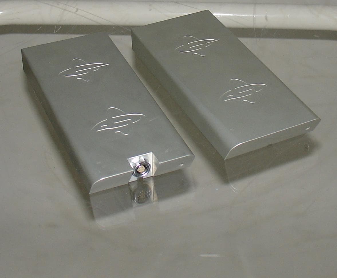
QLA80MHZHDR
Jan 23, 2014Ground Penetrating Radar
Equipment Class
UWB - Ultra Wideband Transmitter