QLACART400
Guideline Geo AB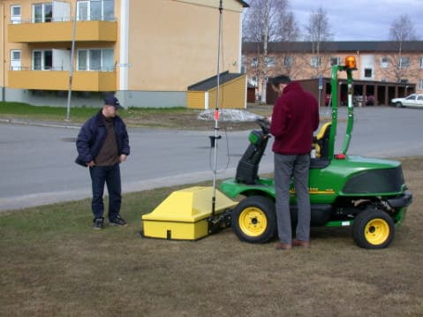
Click to zoom
Application Details
- Equipment Class
- UWB - Ultra Wideband Transmitter
- Date of Grant
- Oct 18, 2004
- Application Purpose
- Original Equipment
- Date of Application
- Jul 11, 2004
- Frequency Range
- 35.00000000 - 593.00000000
- Company
- Guideline Geo AB
- Country
- Sweden
Documents & Files
Document Text
Text extracted from the exhibit documents filed with the FCC. Open a document above to read the original.
Users Manual
Cart400 Operating manual Version 1.0 www.malags.com 2 Table of Contents _________________________________________________ 1 Introduction 3 1.1 Unpacking and Inspection 4 1.2 Repacking and Shipping 4 1.3 Limited Warranty and Liability 4 2 Hardware and Start Up 5 2.1 Hardware 5 2.2 Start up 6 www.malags.com 3 1 Introduction __________________________________________________ Thank you for purchasing the CART400 system, the ultimate system for utility detection. Together with the RAMAC Monitor for data acquisition you have a straightforward one-man operated array system for utility detection and other high-resolution applications. We at Malå GeoScience welcome comments from you concerning the use and experience of this equipment, as well as the contents and usefulness of this manual. Please take the time to read through the assembling instructions carefully and address any questions or suggestions to the following: Main Office: Subsidiary: Malå GeoScience Malå GeoScience USA, Inc. Skolgatan 11 2040 Savage Rd, P.O. Box 80430 S-930 70 Malå Charleston, SC 29416 Sweden USA Phone: +46 953 345 50 Phone: +1-843 852 5021 Fax: +46 953 345 67 Fax: +1-843 769 7397 E-mail: [email protected] E-mail: [email protected] Technical support issues can be sent to: [email protected] Information about MALÅ GeoSciences products is also available on Internet: http://www.malags.com Copyright© 2004 Malå Geoscience AB www.malags.com 4 1.1 Unpacking and Inspection Great care should be taken when unpacking the equipment. Be sure to verify the contents shown on the packing list and inspect the equipment for any loose parts or other damage. All packing material should be preserved in the event that any damage occurred during shipping. Any claims for shipping damage should be filed to the carrier. Any claims for missing equipment or parts should be filed with Mala GeoScience. 1.2 Repacking and Shipping If original packing materials are unavailable, the equipment should be packed in a wooden box with at least 80 mm of absorbing material. Do not use shredded fibres, paper wood, or wool, as these materials tend to get compacted during shipment and permit the instruments to move around inside the package. 1.3 Limited Warranty and Liability Malå Geoscience warrants that, for a period of 12 months from the delivery date to the original purchaser, Malå Geoscience products will be free from defects in materials and workmanship. Except for the foregoing limited warranty, Malå Geoscience disclaims all warranties, express or implied, including nay warranty of merchantability or fitness for a particular purpose. Malå Geoscience will repair and replace parts or equipment which are returned to Malå Geoscience, transportation and insurance pre-paid, without alteration or further damage, and which in Malå Geoscience ́s judgement, were defective or became defective during normal use. Malå Geoscience assumes no liability for any direct, indirect, special, incidental or consequential damages or injures caused by proper or improper operation of its equipment or software, whether or not defective. www.malags.com 5 2 Hardware and Start Up __________________________________________________ 2.1 Hardware The CART400 is a 16 channel array system where the antenna elements, cart control unit and power distribution are mounted in a covered fibreglass box, easily mounted on a small wheel carriage. Such as a car, a tractor or a lawn-mover. See picture below. www.malags.com 6 2.2 Start up When initialising Cart 400 measurements the following easy steps are made to connect and start up the whole GPR system: 1. Connect the DC power input to a fully charged 12 V battery(car battery) or connect it to the 12 V system of the vehicle (Se picture). 2. Connect the laptop to the DSUB-25 connector and the measuring wheel to the DSUB-9 connector. 3. Turn on the power switch on the Cart400. Turn on the laptop and start the Wincart software. Your Cart400 is now ready for operation. www.malags.com 7 Laptop Measuring wheel Power switch
Block Diagram
Block diagram, Cart 400 transmitter Impulse generator and antenna Power input +/- 8 V DC 630 V DC Tx control signal, coax Tx control signal, coax Power supply; +/- 8V 630 V Aluminium shields, inner and outer Absorbents D-sub connector PCB with connectors and current limiting resistors
Cover Letter(s)
Re: FCC ID QLACART400 Applicant: Mala GeoScience AB (publ) Correspondence Reference Number: 27372 731 Confirmation Number: EA894868 1)Please provide internal photo’s of the control box. Internal photos rev 2 filed, containing internal photos of control box. 2) The RMS measurements are made with a 1 mS integration time. Indicate how this was accomplished. For example, what was the number of bins and sweep time of the analyzer during the RMS measurements. To accomplish an integration time of less or equal to 1ms, the spectrum analyzer was set up with the following values. Sweep time: 500ms Number of pixels/bins/presentation values per sweep: 500
External Photos
External photos.
ID Label/Location Info
ID Label/Location info Figure 1. Labels. Figure 3. Location of labels. Figure 2. Placement of the FCC labels at the front of the UWB-unit. Visible at all times.
Internal Photos
Internal photos Overview over interior of Cart400 Overview over interior of Cart400 Tx antenna complete. Showing absorbents both inside shields and also on outside of outer shield. Tx antenna complete, bottom view. Showing antenna flares and loading resistors. Inside antenna top with current limiting resistors and connectors to impulse generator. Inner shield. SMA connector for control signal Connector for impulse generator power Impulse generator, balun and antenna. Impulse generator, balun and antenna. Back side
Internal Photos
Internal photos Overview over interior of Cart400 Overview over interior of Cart400 Tx antenna complete. Showing absorbents both inside shields and also on outside of outer shield. Tx antenna complete, bottom view. Showing antenna flares and loading resistors. Inside antenna top with current limiting resistors and connectors to impulse generator. Inner shield. SMA connector for control signal Connector for impulse generator power Impulse generator, balun and antenna. Impulse generator, balun and antenna. Back side Interior of control unit Control signal distribution section CPU board and timing circuitry DCDC converter board Power distribution board.
Operational Description
1(5) Cart 400 Overview and system description Content 1 Introduction.............................................................................................................................2 2 Overview.................................................................................................................................2 3 Technical Description of Cart 400 transducer.........................................................................4 General...............................................................................................................................4 Operation............................................................................................................................4 2(5) 1 Introduction This document provides an overview of the operation of the Malå GeoScience “Cart 400” system. Pulse generator circuit diagrams as well as module internal photographs are contained in separate documents. 2 Overview The CART Imaging System is the first practical system for making continuous 3D radar images (“radar tomography”) of the subsurface on a large scale. The radar in the standard 400 MHz CART system is a down-looking, ultra-wideband impulse radar, with a pulse spectrum in the bandwidth from about 100 to 650 MHz. The CART uses 9 transmitters and 8 receivers in two parallel rows to create its unique 16-channel GPR array. Spacing between channels in the normal configuration is about 3.25 inches, so the ground “swath” covered by the array is about 4.35 ft wide (1.3 m). The system can fire and collect all 16 channels once every 4 inches (measured along the direction of motion), while moving at speeds up to 1500 ft/hr (0.5 km/hr). Cart 400 is an ultra-wide band system intended for utility detection and non destructive testing. In use the system performs time domain reflectometry by radiating a radio frequency impulse with a repetition rate of 100kHz from a transmitting dipole. Transitions between materials exhibiting different wave impedances through which the electromagnetic wave travels cause the wave to be reflected. These reflections are received by the receiving dipole and sampled inside the antenna units. Results may be presented in real time on the PC connected to the system and recorded on a hard disk on the same PC for later analysis. 3(5) The Cart 400 consists off a fibreglass case with 9 transmitters and 8 receivers and a digital supporting unit that controls firing of transmitters and receivers. It also collects data and send it to a lap-top for further processing. Figure 1. Schematic overview Cart 400 antenna setup. UWB transducer: The shielded transducer comprises, an impulse generator and an antenna element. The pulse generator board is mounted directly on the antenna and it’s surrounded by absorbents and a metal shield. It’s also stuffed with absorbents between the outer aluminum housing ant the inner metal shield. There is also absorbents on the outside of the outer shield. 12 V DC power and control signal is fed to the transducer via a voltage converter unit, mounted at the top of the transducer. Control signal, +/-8 V and 630 V are then fed to the transducer via a D-sub connector. Inside the transducer, in a shielded compartment there is a PCB with current limiting resistors and connectors to the impulse generator. Power supply: The Cart 400 system is powered from a 12 V Lead/acid battery. T1 T2 T3 T4 T5 T6 T7 T8 T9 R1 R2 R3 R4R5R6 R7 R8 4(5) 3 Technical Description of Cart 400 transducer General A block diagram of a shielded transducer is shown in figure 2 below. The transducer housing is made of aluminum. It’s made like a box, open on one side(bottom), where the antenna and impulse generator is placed. In the top of the box there is a small compartment in which the PCB with current limiting resistors and connectors to the impulse generator is placed. Power and control signal is fed to the impulse generator trough cables and a coax through this PCB. The antenna and impulse generator are surrounded with an extra metal shield. Both inner and outer shield is stuffed with absorbents. No rf-signals leave the transducer trough connectors. Operation In the transmitter, high voltage DC-power, transmitter control signal as well as ground reference are fed to the impulse generator on top of the antenna element. The impulse created is fed to the antenna element. The antenna element is situated on an electromagnetic absorbing material and resistively loaded at its endpoints. 5(5) Figure 1. Schematic overview of the Cart 400 transmitter unit. Impulse generator and antenna Power input +/- 8 V DC 630 V DC Tx control signal, coax Tx control signal, coax Power supply; +/- 8V 630 V Aluminium shields, inner and outer Absorbents D-sub connector PCB with connectors and current limiting resistors
Schematics
1 (2) MALÅ GeoScienceKOMPONENTLISTA RitningsnrRevisionBenämningDatum / Sign 12-0018515 Pulsgenerator, gemensam skärmade antenner20021002KJa Ändringsmeddelande Pos 16, 30, 31,32 äro ändrade PosNamnTypTillverkareStorlekArt.nr / Tel.nrLeverantör 1KORT 13-00185113-001851.PCBUlf Andersson 2R151 ohm120660-191-86ELFA 3R21.2 kohm120660-195-17ELFA 4R34.3 kohm120660-196-40ELFA 5R4430 ohm120660-194-00ELFA 6R51.2 kohm120660-195-17ELFA 7R62 kohm120660-195-66ELFA 8R710 ohm1206ELFA 9R810 ohm1206ELFA 10R9150 ohm1206ELFA 11R1051 ohm120660-191-86ELFA 12R110 ohm120660-199-05ELFA 13R122 kohm1206ELFA 14R13510 ohm1206ELFA 15C147pF0805ELFA 16C222pF080567-798-25ELFA 17C30 ohm0805ELFA 18C45pF MicaMICA121008-757 49 00Ericsson 19C53pF MicaMICA121008-757 49 00Ericsson 20C6 4.7 uF 352867-738-65ELFA 21C7 4.7 uF 352867-738-65ELFA 22C80.1 uF120665-776-88ELFA 23C90.1 uF120665-776-88ELFA 24C1015 nF0805ELFA 25D1150 VSOD106ABZG03C150Farnell 26D2150 VSOD106ABZG03C150Farnell 27D3150 VSOD106ABZG03C150Farnell 28D4150 VSOD106ABZG03C150Farnell 29D5BAV99SOT 23BFI-IBEXA 30L1680ohm080560-174-53ELFA 31L2680ohm080560-174-53ELFA 32L3Byglas 33Q1AT41511SOT-14308-629 99 00BFI-IBEXSA 34Q2BFT 92SOT-2308-760 01 40Hatteland 35Q3BFG 19SSOT-22308-760 01 40Hatteland 36Q4BFG 194SOT-22308-760 01 40Hatteland 37Q5FMMT 415SOT-2308-757 49 00Ericsson 38Q6FMMT 415SOT-2308-757 49 00Ericsson 39K185-SMA-50-0-108-636 26 00Carlberg & son 40Stub*RG405U/UT85monteras ej40 mm711-287Farnell 41Skärmstrumpa100 mm55-085-10ELFA 42 43BalunTP 101 44* Monteras av MGS 45 46 47 48 49 50 51 52 53 54 55 56 57
Test Report
AerotechTelub AB Box 360 831 25 Östersund Besöksadress: Storlienvägen 56 Telefon: 063-15 60 00 Fax: 063-15 61 99 Huvudkontor 732 81 Arboga Telefon: 0589-800 00 Fax: 0589-61 16 52 Org. nr: 556218-6790 Styrelsens säte: Arboga Överföring av dokument i elektronisk form Detta dokument är en elektronisk kopia. Vid konvertering eller överföring i elektronisk form kan dokumentet bli förvanskat. Det fastställda pappersoriginalet är det gällande dokumentet. Transfer of document in electronic form This document is an electronic copy of the original. When converting or transferring the document into electronic form, it could be distorted. The original paper document is to be considered the valid document. AerotechTelub AB Box 360. SE-831 25 Östersund, Sweden. Visitors: Storlienvägen 56. Telephone: +46 63 15 61 00. Telefax: +46 63 15 61 99 Internal Ref No 91170-78531-0100 D istribution Malå Geoscience AB Bernth Johansson Skolgatan 11 930 70 Malå Copy FB/archive, FBM/archive D ocument Test Report Date June 21, 2004 Prepared FBM, Per Larsson EMC Test Engineer R ef. No E014-TR 040065 S upersedes P age 1 (23) T itle EMC Test, Cart 400 Equipment under test (EUT): Description: Ground Penetrating Radar System Manufacturer: Malå Geoscience AB Model name: Cart 400 Summary: The EUT complied with the requirement of radiated emissions given in FCC Part 15 Subpart F, measured in the frequency range 30 – 10 000 MHz. Approved: Petter Gärdin EMC Test Supervisor R ef No E014-TR 040065 P age 2(23) AerotechTelub AB Contents 1 Introduction ..................................................................................................................3 2 Test methods and results ..............................................................................................4 2.1 Results..............................................................................................................4 3 Applicable documents ..................................................................................................4 4 Equipment under test (EUT) ........................................................................................5 4.1 Identification of equipment under test .............................................................5 4.2 General configuration of EUT .........................................................................5 4.3 Operation of EUT during tests.........................................................................5 4.4 Modification of EUT .......................................................................................6 5 Test site ........................................................................................................................7 5.1 Description.......................................................................................................7 5.2 Ambient signals ...............................................................................................7 6 Emission .......................................................................................................................8 6.1 Measurement of radiated emission, ANSI C63.4 ............................................8 6.2 Measurement of radiated emission ................................................................13 6.3 Measurement of UWB bandwidth and peak emissions .................................19 R ef No E014-TR 040065 P age 3(23) AerotechTelub AB 1 Introduction The object of the test is to show compliance with the emission requirements of FCC Part 15 Subpart F. Date of test: Mars 29 – 31, 2004 Location: AerotechTelub AB, Östersund Test performed by: Per Larsson, AerotechTelub / FBM Client: Malå Geoscience Skolgatan 11 SE-930 70 Malå Sweden Client’s observer: Lars Mikaelsson, Malå Geoscience AB R ef No E014-TR 040065 P age 4(23) AerotechTelub AB 2 Test methods and results 2.1 Results The test results in this report apply only for the tested specimen. The results in this table are only valid with the modifications of the EUT specified in section 4.4. EMISSION REQUIREMENTS ACCORDING TO FCC Part 15 Subpart F Environmental phenomena Test method Requirement Result Comments Test order Radiated emission ANSI C63.4 FCC 15.209 PASS 1 UWB definition FCC 15.503 (a) 15.509(a) PASS f L 35 MHz f C 314 MHz f H 593 MHz 4 Peak emission at f M FCC 02-42 FCC 15.509 (f) PASS 5 Radiated emission FCC 02-42 FCC 15.509 (d) PASS 2 Radiated emission FCC 02-42 FCC 15.509 (e) PASS 3 3 Applicable documents Measurements ANSI C63.4 07/17/1992 Radio noise emissions from low-voltage electrical and electronic equipment in the range of 9 kHz to 40 GHz. FCC Part 15 12/8/2003 Radio Frequency Devices FCC 02-42 4/22/2002 Revision of Part 15 of the Commission’s Rules Regarding Ultra- Wideband Transmission Systems R ef No E014-TR 040065 P age 5(23) AerotechTelub AB 4 Equipment under test (EUT) 4.1 Identification of equipment under test Equipment under test (EUT): Description: Ground Penetrating Radar System Manufacturer: Malå Geoscience AB Model name: Cart 400 Build state: Production sample Serial no: 12627 4.2 General configuration of EUT A battery powered the EUT. The EUT was placed directly on the dry sand with no ground plane under it. 4.3 Operation of EUT during tests The EUT was gathering data like in normal operation. R ef No E014-TR 040065 P age 6(23) AerotechTelub AB 4.4 Modification of EUT Picture 1. EUT The EUT was modified as below before the tests. •The shielding of the Cart control unit was improved. The electrical contact between the casing and the cover was improved. •The ground of the digital control and data signals BNC-connectors were connected to the casing. •Improved shielding of control cable. R ef No E014-TR 040065 P age 7(23) AerotechTelub AB 5 Test site 5.1 Description The measurements were all performed on a weather protected open area test site that was modified with a flat sand bed located in the ground plane. The sand bed is about 50 cm deep. Picture 2: Test Site The measurement distance antenna…
Text truncated - open the document above for the full version.
Contact Information
Applicant
Johan Friborg(Research lead GPR)
Test Firm
AerotechTelub ABPetter G�rdin
Technical Specifications
| # | Rule Parts | Frequency Range | Power Output |
|---|---|---|---|
| 1 | 15F | 35 MHz - 593 MHz | - |
Other Applications from Guideline Geo AB

QLA-MIRAHDR500
Apr 15, 2020GPR Array System
Equipment Class
UWB - Ultra Wideband Transmitter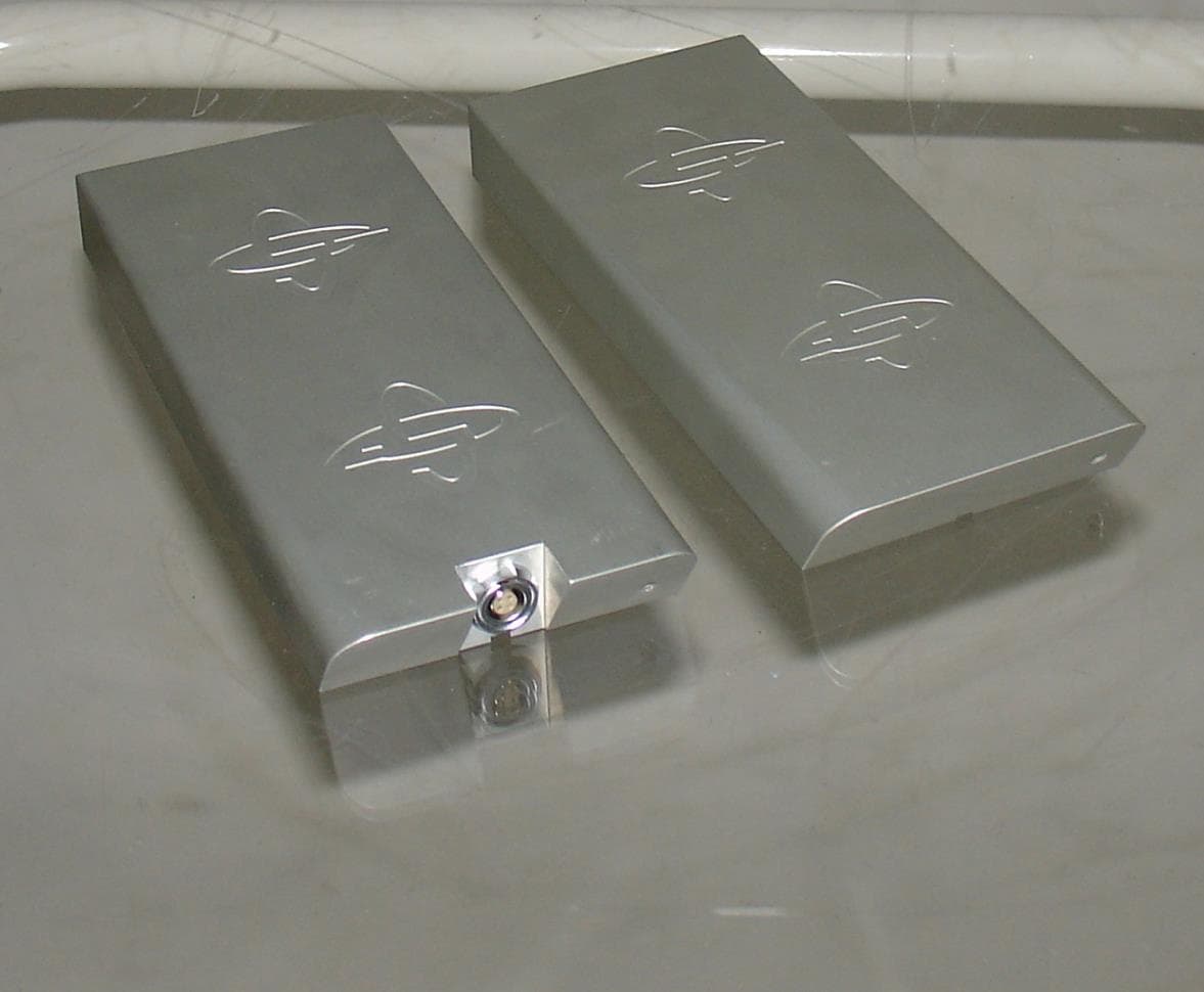
QLA450MHZHDR
May 17, 2014Ground Penetrating Radar
Equipment Class
UWB - Ultra Wideband Transmitter
QLA160MHZHDR
Jan 23, 2014Ground Penetrating Radar
Equipment Class
UWB - Ultra Wideband Transmitter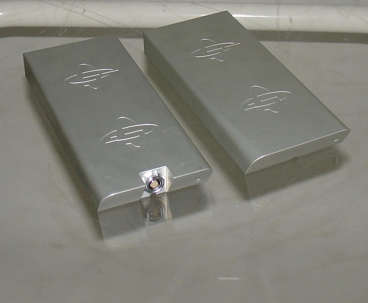
QLA750MHZHDR
Jan 23, 2014Ground Penetrating Radar
Equipment Class
UWB - Ultra Wideband Transmitter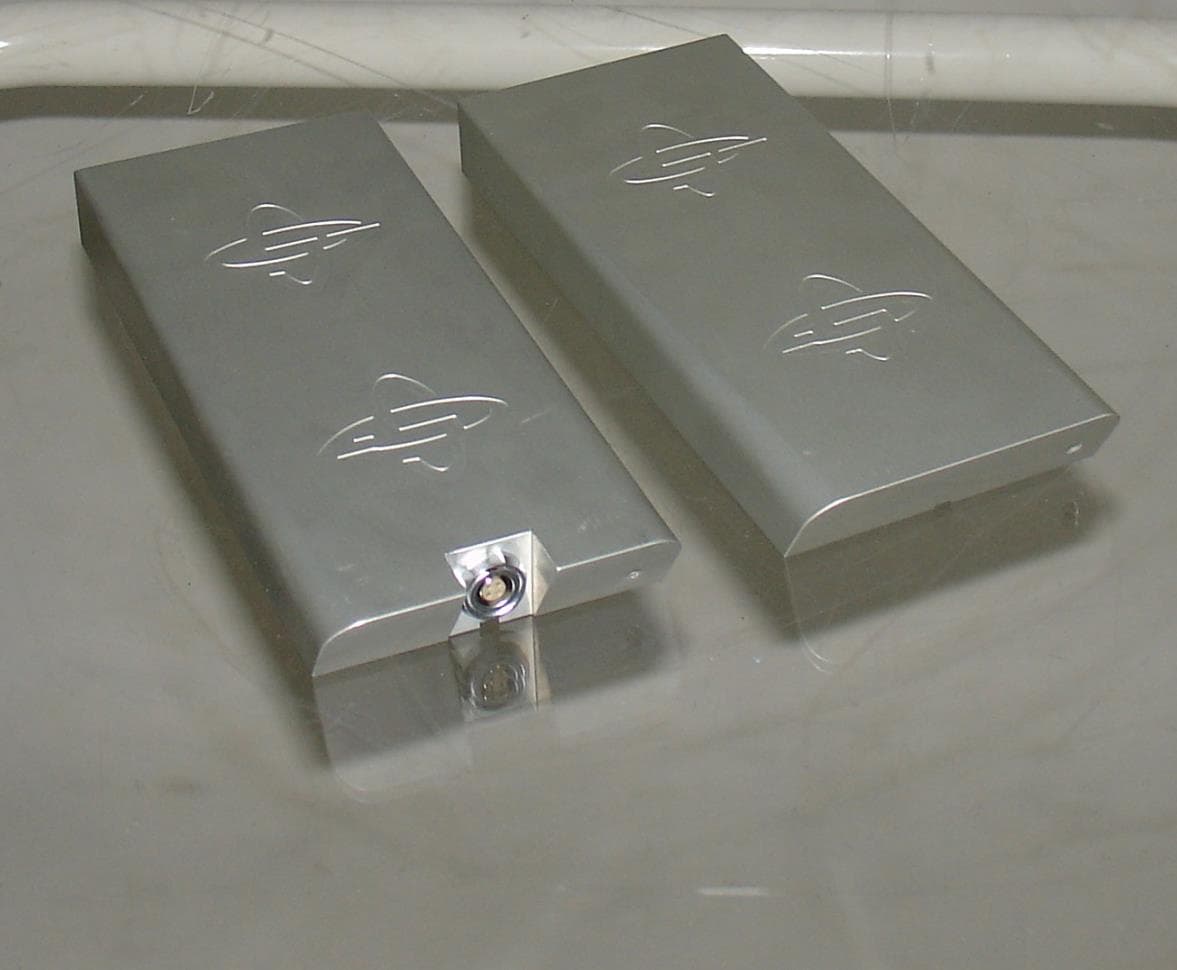
QLA80MHZHDR
Jan 23, 2014Ground Penetrating Radar
Equipment Class
UWB - Ultra Wideband Transmitter