QLASH1GHZGPR
Guideline Geo AB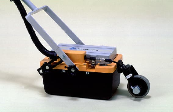
Click to zoom
Application Details
- Equipment Class
- UWB - Ultra Wideband Transmitter
- Date of Grant
- Apr 20, 2004
- Application Purpose
- Original Equipment
- Date of Application
- Nov 20, 2003
- Equipment Note
- GPR
- Frequency Range
- 240.00000000 - 1800.00000000
- Company
- Guideline Geo AB
- Country
- Sweden
Documents & Files
Document Text
Text extracted from the exhibit documents filed with the FCC. Open a document above to read the original.
Users Manual
RAMAC/GPR Operating manual Version 1.0 www.malags.com 2 Table of Contents _________________________________________________ 1 Introduction 4 1.1 Unpacking and Inspection 5 1.2 Repacking and Shipping 5 2 General 6 2.1 General description of the GPR Technique 6 2.2 Basic information in investigation depths and velocities 8 3 Radar Control Unit CUII 11 4 Unshielded antennas 14 4.1 Antenna electronics 14 4.2 Antenna elements 16 4.3 Operation modes 18 5 Shielded antennas 20 6 1 GHz shielded antenna 24 7 Power supply, Optical fibres and Communication cables 26 7.1 Power supply 26 7.2 Optical fibres 27 7.3 Communication cable 28 8 Multi-channel modules 30 9 Trigger devices 32 www.malags.com 3 10 Other accessories 34 10.1 Antenna handles 34 10.2 Skid box 35 10.3 Antenna Sled 36 11 Start up of your RAMAC/GPR CUII 38 11.1 Connecting the system components 39 11.2 Running a survey 40 12 Trouble shooting 42 13 How to assemble the RAMAC/GPR Cart 44 www.malags.com 4 1 Introduction __________________________________________________ Thank you for purchasing the RAMAC/GPR system. We at Malå GeoScience welcome comments from you concerning the use and experience of this equipment, as well as the contents and usefulness of this manual. Please take the time to read through the assembling instructions carefully and address any questions or suggestions to the following: MALÅ GeoScience postal address is: Main Office: Subsidiary: Malå GeoScience Malå GeoScience USA, Inc. Skolgatan 11 2040 Savage Rd, P.O. Box 80430 S-930 70 Malå Charleston, SC 29416 Sweden USA Phone: +46 953 345 50 Phone: +1-843 852 5021 Fax: +46 953 345 67 Fax: +1-843 769 7397 E-mail: [email protected] E-mail: [email protected] Technical support issues can be sent to: [email protected] Information about MALÅ GeoSciences products is also available on Internet: http://www.malags.com www.malags.com 5 1.1 Unpacking and Inspection Great care should be taken when unpacking the equipment. Be sure to verify the contents shown on the packing list and inspect the equipment for any loose parts or other damage. All packing material should be preserved in the event that any damage occurred during shipping. Any claims for shipping damage should be filed to the carrier. Any claims for missing equipment or parts should be filed with Mala GeoScience. 1.2 Repacking and Shipping If original packing materials are unavailable, the equipment should be packed with at least 80 mm of absorbing material. Do not use shredded fibers, paper wood, or wool, as these materials tend to get compacted during shipment and permit the instruments to move around inside the package. www.malags.com 6 2 General _________________________________________________ 2.1 General description of the GPR Technique In its simplest form the RAMAC/GPR system consists of an external PC, a Radar Control Unit, a transmitter antenna and a receiver antenna. The Radar Control Unit is connected to the transmitter and the receiver antenna with optical fibres and to the computer with a parallel communication cable. Figure 2.1 shows a schematic diagram of the system when connected. Note that this picture refers to the case where the transmitter and receiver are located in different modules. The general principle is still the same also for shielded antennas. Figure 2.1 General description of the principle In GPR context the following terminology is often used: Sample: In a digital system, the incoming signal (to the receiving antenna) is measured a certain number of times per unit of time. The result of every such measurement is a numeral, a sample. A defined number of samples are used to construct a trace. www.malags.com 7 Trace: At each point of measurement along the profile, a specific number of samples are collected. Together, these samples make up a trace, an envelope of the received waveform. Profile: A collection of traces along a line or transect. Direct wave: This is the part of the energy that travels the shortest distance between the transmitter and the receiver. When collecting a sample, the CUII sends a timing signal (a control signal) to the transmitter and receiver antenna respectively. After the transmitter has received the signal, it generates and transmits radar pulses through the antenna. The pulse then propagates through the medium. Reflections occur from underground objects, structures and other materials where there are changes in subsurface electrical properties. Once the receiver has detected the control signal, it collects a sample and passes it to the CUII. By repeating this process at very finely controlled intervals, the CUII can collect all the samples in a trace. The CUII places each incoming sample in its correct position in the current trace. When the trace is complete, it is sent to the computer where it is saved on the hard disk and displayed on the computer monitor. During data collection, the whole system is transported along the line to be investigated, while collecting and recording traces at defined distance or time intervals. The result is a continuous profile record of subsurface conditions along that line (see Fig 2.2), a so-called radargram. www.malags.com 8 SOIL LAYERS BOULDER Distance D e p t h SURFACE Figure 2.2 An example of a continuous record of radar traces. 2.2 Basic information in investigation depths and velocities The problem of range (depth) vs. resolution is well known for the type of investigations that GPR represents. Sufficient penetration depth may be achieved but it may require a low frequency that reduces the resolution. Range is defined as the distance at which a target can be detected. Resolution on the other hand is defined as the smallest size an object or thinnest layer that may be detected. There often is a compromise regarding the choice of antenna frequency for a particular application at a specific site. The depth penetration with different frequency antennas varies greatly depending on local soil conditions. Primarily the depth/resolution …
Text truncated - open the document above for the full version.
Block Diagram
1 Block diagram 1 GHz antenna. Optoconverter and power supply HV-supply 600 V DC, 60 mA max Sampler and AD-converter Impuls gene- rator Pre amp Optical signals for trig and data Antenna elements Metal shield Absorbents Plastic cover TTL-trig signal TTL-trig signal Attached 8 V battery Power input
Cover Letter(s)
October 3, 2003 COVER LETTER Re: Malå GeoScience AB, application for Ground Penetrating Radar FCC ID: QLASH1GHZ Dear Sirs, This application is for the product; Ramac/GPR 1 GHz shielded antenna. Best regards Bernth Johansson Head R&D Malå GeoScience Skolgatan 11 S-930 70 Malå Sweden
Cover Letter(s)
Re. FCC ID: QLASH1GHZ Applicant: Mala GeoScience AB(publ) Correspondence reference number: 26103 and 26102 731 Confirmation number: EA827998 Answers in bold. 1. Please explain/correct the –35dB cable loss listed/used in all RMS measurements. In all the tables in the report the cable loss is stated as a positive number. During the measurements above 1 GHz the values in column 'cable loss' is a result of loss measurement of the whole cable from antenna to the measurement receiver including a preamplifier placed at the antenna. The result is a negative loss i.e. a gain. 2. Please list the spectrum analyser used that is capable of RMS detection. The spectrum analyzer used for the RMS measurements is listed under point 5.3.4 Instrumentation and is the Rohde & Schwartz FSP 40. 3. The label(s) must include information per Section 15.19(a)3. New document “Idlabel ver 2” with description “New idlabels and location” filed. 4. What is the pulse width? The pulse width is 1.1099 nS. 5. Was the signal continuously transmitting at the pulse repetition rate stated or was the signal transmitted periodically(gated or burst transmission)? The signal was transmitted continuously. 6. Internal and external photos of the transmitter control unit(CUII). The CUII(control unit) is a class A device that is used with the system. It’s not a part of the UWB unit. 7. Photos of both sides of the PCB boards. The photo(picture 6) of the transmitter was unclear. New document “Internal photos ver 2” with description “New internal photos” filed. 8. Provide a block diagram that shows the frequencies, signal path, oscillators per 2.1033(b)5. New document “Overview of 1 GHz ver 2” with description “New overview of 1GHz” filed. 9. Indicate compliance with the manually operated switch requirement in Section 15.509(c). The dead man switch must be depressed during operation and when released, transmitter must cease within 10 seconds. The 1GHz unit is not, as stated in section 15.504(m) and 15.519(a),primarily handheld. Or meant for vertical use. The weight of the unit is 5.2 kg and it's not practical to use such a heavy unit handheld or on vertical surface. The attached photo originates from a brochure, made with a prototype of unknown weight. New document “External photos ver 2” with description” New external photos” filed. 10. What are the peak levels obtained at Fl(227 MHz) and Fh(1728 MHz)? Were these levels the highest and lowest peak levels that were 10 dB below peak emission? The measurement of the bandwidth is divided into 2 frequency ranges, above and below 1 GHz. These measurements have been performed at different distances. Because of this the - 10 dB points are difficult to obtain. The frequencies in the report Fl (227MHz) and Fh (1728 MHz) have been taken relative the point of peak emission Fm (1000 MHz). The value of Fl emission is 35 dBμV/m and the value of Fh is 25 dBμV/m. Fl is 10 dB below Fm at the measurement below 1 GHz and Fh is 10 dB below Fm at the measurement above 1 GHz. The difference in absolute emission levels is due to the fact that there are different measurement setup properties below and above 1 GHz. The Fl and Fh are based on the relative (-10dB) deviation from the measured Fm emission level in each frequency range.
Cover Letter(s)
Re. FCC ID: QLASH1GHZ Applicant: Mala GeoScience AB(publ) Correspondence reference number: 26250 731 Confirmation number: EA827998 Answers in bold. 1. Internal and external photo's of the transmitter control unit (CCUII). The CCUII is not a separate standalone digital device. It is the control unit and is an essential part of the transmitter. The control unit is a digital device which is used to produce trig signals and transfer data from the UWB-unit to a PC as well as from other instruments to the same PC. The only connection between the control unit and the UWB-tranmitter is an optical fibre. The control unit is not essential for producing the transmitter trig signal. Any 100kHz optical signal will produce exactly the same RF-emission. A higher trig frequency does not produce any higher emission since the charging of the pulse generator is current limited. This means that it cannot charge any quicker then 10 μS(100 kHz). We’ve not been asked to file any information regarding the control unit for previous applications (QLA250MHZ, QLA500MHZ, QLA800MHZ). Also, no other, published, application contain such information even though it’s clear that there’s a control unit involved when the transducers are used. Therefore we don’t understand why we should be forced to file information on the control unit. 2. Provide a block diagram that shows the frequencies, signal path, oscillators per 2.1033(b)5. This was not submitted in the last reply. New Document filed containing more details of the receiver is filed. 2.1033(b)5 is actually not applicable in this case since this isn’t a radio receiver with oscillators, mixers ant tuned stages. This is a digital system with one crystal controlled oscillator (7.94 MHz)and a frequency divider, all mounted in a shielded metal box. 3.The UWB bandwidth needs to be determined. The -10 dB points cannot be determined by two different peak emissions as you had explained in your last reply. You also had stated that the measurement setup was different below 1 GHz and above 1 GHz. The measurement set up should be similar(same detector, same distance etc...) throughout the emission profile in order to help determine the correct 10 dB points. From the overall peak of the emission, re-measure to find the - 10 dB points furthest from this peak emission to indicate the UWB bandwidth. Addendum to previously filed test report, containing new bandwidth measurement, filed. Document name: TR040118 SH1GHZ.pdf
Cover Letter(s)
Cover letter Re: QLASH1GHZ, EA827998 Correspondence ref no: 26596 Request for not to hold internal photos confidential Although we still believe the CUII is not part of the UWB-device we request that the internal photos should be held non-confidential since this issue seems to delay the application significantly. Bernth Johansson Head R&D Malå GeoScience
External Photos
Exterior Photos of 1GHz unit Picture 1. 1GHz unit with battery and distance encoder Picture 2. 1GHz with cable hose Cover for optical fibres Battery Connector for distance encoder On/Off switch Fibre connectors Connector for distance encoder Protection hose for fibres Picture 3. 1GHz unit with handle. Picture 4. Handheld measurement on wall and on floor
External Photos
External Photos of 1GHz unit Picture 1. 1GHz unit with battery and distance encoder Picture 2. 1GHz with cable hose Cover for optical fibres Battery Connector for distance encoder On/Off switch Fibre connectors Connector for distance encoder Protection hose for fibres Picture 3. UWB unit with handle. Picture 4. Measurement on floor.
External Photos
External photos CUII As Mala's lawyer has explained in emails to Mr. Dichoso, we think the digital controller (CUII) is properly treated as a digital device subject only to verification to Class B standards, so the Commission should not require photos and block diagrams. We are submitting these materials anyway to expedite a grant of the present application. But we intend to seek clarification of the rules applicable to digital devices that control UWB transmitters." Figure 1. Front site of CUII. Figure 2. Back side of CUII. Figure 3. Side view of CUII
ID Label/Location Info
ID Label/Location info Figure 1. Label. Figure 2. Placement of the FCC label on top of the UWB-unit. 51mm 32mm
ID Label/Location Info
Re. FCC ID: QLASH1GHZ Applicant: Mala GeoScience AB(publ) Correspondence reference number: 26042 and 26041 731 Confirmation number: EA827998 Answers in bold. 1. The FCC ID is not shown on the identification label. Submit a revised identification label showing the FCC ID pursuant to Section 2.925(a) of the FCC Rules. New document “Idlabel ver 2.pdf” with description “New id labels and location” filed. This document shows these pictures: Picture 1. Text on labels Picture 2. Labels on UWB unit
ID Label/Location Info
ID Label/Location info Figure 1. Labels. 51mm 32mm Figure 2. Placement of the FCC labels at the front of the UWB-unit. Visible at all times.
Internal Photos
Internal photos of 1GHz unit. Picture 1. 1GHz unit without plastic cover and shield. Picture 2. Without absorbents. Tx-antenna Rx-antenna Impulse generator Absorbents Pre-amplifier Picture 3. Plastic cover with EMC-shield. Picture 4. PCB ́s under aluminum lid. Picture 5. Transmitter antenna board with required modifications according to section 4.5 in testreport. Picture 6. Antenna board with impulse generator. RA1=22 Ohm R1 = 82 Ohm
Internal Photos
Internal photos of 1GHz unit. Picture 1. 1GHz unit without plastic cover and shield. Picture 2. Without absorbents. Tx-antenna Rx-antenna Impulse generator Absorbents Pre-amplifier Picture 3. Plastic cover with EMC-shield. Picture 4. PCB ́s under aluminum lid. Picture 5. Backside of main board Picture 6. Backside of High voltage PCB Picture 7. Backside of Sampler board Picture 8. Transmitter antenna board with required modifications according to section 4.5 in testreport. Picture 9. Antenna board with impulse generator. RA1=22 Ohm R1 = 82 Ohm Picture 10. Backside of impulse generator.
Operational Description
Ramac/GPR 1GHz Overview and system description Content 1 Introduction.............................................................................................................................2 2 Overview.................................................................................................................................2 3 Operation setups......................................................................................................................3 4 Overview Technical Description of main 1GHz Modules.....................................................4 4.1 CUII overview..................................................................................................................4 4.2 Shielded antenna overview..............................................................................................4 General...............................................................................................................................4 Operation............................................................................................................................4 2(7) 1 Introduction This document provides an overview of the operation of the Malå GeoScience Ground Penetrating Radar “Ramac/GPR 1GHz”. Pulse generator circuit diagrams as well as module internal photographs are contained in separate documents. 2 Overview Ramac/GPR 1GHz is an ultra-wide band radar intended for geophysical surveying and non destructive testing. In use the system performs time domain reflectometry by radiating a radio frequency impulse with a repetition rate of 100kHz from a transmitting dipole. Transitions between materials exhibiting different wave impedances through which the electromagnetic wave travels cause the wave to be reflected. These reflections are received by the receiving dipole and sampled inside the antenna units. Results may be presented in real time on the PC connected to the system and recorded on a hard disk on the same PC for later analysis. One or several rechargeable batteries, dependent on the setup, power the system. The system may be carried with the antenna (a distance encoder wheel may be attached to the antenna) being dragged along the ground by a simple pull handle or it may be mounted on a trolley incorporating a distance encoder. When used for data capture, 1GHz comprises the following items: PC On the PC the data collection software runs. The unit communicates with the CUII control unit via the parallel port. On the screen is the result shown in real time while the data are stored on the hard disk. The customer himself usually provides the PC. None of the existing acquisition software’s makes it possible to change the behaviour of the transmitting and receiving electronics of the antenna. CUII control unit This unit are mounted on a back pack or a cart and control the firing of the transmitting antennas as well as the sampling and digitizing of received waveforms. It communicates with the PC via the parallel port and with the antenna via optical fibres. Antenna: The shielded antenna comprises, on the transmitter side, an impulse generator, a transformer and an antenna element. On the receiver side there’s a similar antenna and transformer, a preamplifier and a sampler head. The sampler head is mounted inside a fully shielded metal box and electromagnetic absorbing materials surround both the antennas. On the perimeter of the absorbing materials there are metallic shields. The box 3(7) also contains AD-converter and optoconverters for trigger signals and data output Distance encoders: The distance encoders are commonly used for positioning each sampled wavelet with respect to its neighbors. It’s mounted on the antenna or on the cart and connected to the CUII. Battery pack: The 1GHz is powered from an external battery pack. Different types and power ratings are available. 3 Operation setups In figure 1 below a typical setup during measurement with an 1GHz is shown. The CUII unit is connected to the PC. Communication between the two units is done over the IEEE1284 ECP protocol. The CUII is also connected to the antenna through optical fibres and to the distance encoder through a cable. Attached rechargeable batteries power the CUII and the antenna. The nominal voltage of the units is 7.2V, DC. Via the data acquisition software running on the PC, the operator selects a number of suitable measurement parameters e.g. sampling frequency, time window and the amount of averaging. A number of different acquisition software’s are available; with different levels of complexity e.g. the simplest software does not allow the user to adjust any parameter at all! Figure 1. Operation setup for the 1GHz system. PC CUII Control unit Battery Optical fibres Cable Battery 1GHz antenna 4(7) When an acquisition is started the CUII continuously counts the pulses from the pulse encoder mounted on the measuring wheel and by counting the forward and backward pulses and then subtracting, it keep track of the absolute position along the profile. At predetermined positions along the profile the unit gathers waveform envelopes and transfer these 5 times every second to the PC. If a distance encoder/measuring wheel is not used the CUII can be set to gather waveforms at a certain rate/s. 4 Overview Technical Description of main 1GHz Modules 4.1 CUII The CUII is a class A device . 4.2 Shielded antenna overview. General A block diagram of a shielded antenna is shown in figure 3 below. All sides of the antenna, except the bottom, have metal shielding. A d-sub connectors on top of the antennas provide the necessary power from the battery. No rf-signals leave the antenna trough connectors. All signals to and from the unit is through optical fibres Operation On the transmitter side high voltage, DC-power, transmitter trig signal as well as ground reference are directly fed to the impulse generator on top of the antenna element. When a trig condition is received via the optical fibre, a ch…
Text truncated - open the document above for the full version.
Operational Description
Ramac/GPR 1GHz Overview and system description Content 1 Introduction.............................................................................................................................2 2 Overview.................................................................................................................................2 3 Technical Description of 1GHz Module................................................................................3 General...............................................................................................................................3 Operation............................................................................................................................3 2(7) 1 Introduction This document provides an overview of the operation of the Malå GeoScience Ground Penetrating Radar “Ramac/GPR 1GHz transducer”. Pulse generator circuit diagrams as well as module internal photographs are contained in separate documents. 2 Overview Ramac/GPR 1GHz is an ultra-wide band transducer intended for geophysical surveying and non destructive testing. In use the system performs time domain reflectometry by radiating a radio frequency impulse with a repetition rate of 100kHz from a transmitting dipole. Transitions between materials exhibiting different wave impedances through which the electromagnetic wave travels cause the wave to be reflected. These reflections are received by the receiving dipole and sampled inside the antenna units. Results may be presented in real time on the PC connected to the system and recorded on a hard disk on the same PC for later analysis. A rechargeable batteries powers the system. The system may be dragged along the ground by a simple pull handle or it may be mounted on a trolley incorporating a distance encoder. UWB transducer: The shielded transducer comprises, on the transmitter side, an impulse generator, a transformer and an antenna element. On the receiver side there’s a similar antenna and transformer, a preamplifier and a sampler head. The sampler head is mounted inside a fully shielded metal box and electromagnetic absorbing materials surround both the antennas. On the perimeter of the absorbing materials there are metallic shields. The box also contains AD-converter and optoconverters for trigger signals and data output Distance encoders: The distance encoders are commonly used for positioning each sampled wavelet with respect to its neighbors. It’s mounted on the antenna or on the trolley and connected to the data acquisition unit. Battery pack: The 1GHz is powered from an external battery pack. Different types and power ratings are available. 3(7) 3 Technical Description of 1GHz Module General A block diagram of a shielded transducer is shown in figure 1 below. All sides of the transducer, except the bottom, are metal shielded. A d-sub connector on top of the transducer provide the necessary power from the battery. No rf-signals leave the transducer trough connectors. All signals to and from the unit is through optical fibers Operation On the transmitter side high voltage, DC-power, transmitter trig signal as well as ground reference are directly fed to the impulse generator on top of the antenna element. When a trig condition is received via the optical fiber, a charge storage capacitor is de-charged trough a set of avalanche transistors and current limiting resistors. The impulse created during this discharge is fed, via a 1:4 balun (not shown in the figure below) to the antenna element. The antenna element is situated on an electromagnetic absorbing material and resistively loaded at its endpoint. On the receiver side DC-power, receiver trig signal and ground reference is fed to the sampler head located in a shielded cavity in the upper part of the antenna. DC-power and ground reference is fed to the preamplifier located on top of the antenna element. The antenna element is identically mounted as on the transmitter side. 4(7) Figure 1. Block schematic of the 1GHz antenna. Incoming signals are fed from the antenna element to the preamplifier, 18dB low noise, via a 1:1 balun (not shown on the figure above). From the preamplifier the signal is fed to the sampler head via a semi-rigid transmission line. A trig condition on the receiver fiber causes the sampler head to sample the analog level of the signal arriving from the preamplifier. The sampled signal is fed to the AD-converter and then to the optoconverter and through the fiber to a data acquisition unit. Plastic cover HV-supply 600 V DC, 60 mA max Sampler and AD-converter Im- pulse gene- rator Pre amp Optical signal for transmitter trig. Antenna elements Metal shield Absorbents TTL-trig signal TTL-trig signal Attached 8 V battery Power input Optical signal for receiver trig. Optical signal for data transfer Optoconverter for data and trigger signals
Schematics
1 (2) MALÅ GeoScienceKOMPONENTLISTA RitningsnrRevisionBenämningDatum / Sign 12-0018515 Pulsgenerator, 1 GHz20021002KJa Ändringsmeddelande Pos 16, 30, 31,32 äro ändrade PosNamnTypTillverkareStorlekArt.nr / Tel.nrLeverantör 1KORT 13-00185113-001851.PCBUlf Andersson 2R151 ohm120660-191-86ELFA 3R21.2 kohm120660-195-17ELFA 4R34.3 kohm120660-196-40ELFA 5R4430 ohm120660-194-00ELFA 6R51.2 kohm120660-195-17ELFA 7R62 kohm120660-195-66ELFA 8R710 ohm1206ELFA 9R810 ohm1206ELFA 10R922pF1206ELFA 11R1051 ohm120660-191-86ELFA 12R1182 kohm120660-199-05ELFA 13R122 kohm1206ELFA 14R13510 ohm1206ELFA 15C122pF0805ELFA 16C222pF080567-798-25ELFA 17C30 ohm0805ELFA 18C48pFMICA121008-757 49 00Ericsson 19C54pFMICA121008-757 49 00Ericsson 20C6 4.7 uF 352867-738-65ELFA 21C7 4.7 uF 352867-738-65ELFA 22C80.1 uF120665-776-88ELFA 23C90.1 uF120665-776-88ELFA 24C1015 nF0805ELFA 25D1150 VSOD106ABZG03C150Farnell 26D2150 VSOD106ABZG03C150Farnell 27D3150 VSOD106ABZG03C150Farnell 28D4150 VSOD106ABZG03C150Farnell 29D5BAV99SOT 23BFI-IBEXA 30L1680ohm080560-174-53ELFA 31L2680ohm080560-174-53ELFA 32L3Byglas 33Q1AT41511SOT-14308-629 99 00BFI-IBEXSA 34Q2BFT 92SOT-2308-760 01 40Hatteland 35Q3BFG 19SSOT-22308-760 01 40Hatteland 36Q4BFG 194SOT-22308-760 01 40Hatteland 37Q5FMMT 415SOT-2308-757 49 00Ericsson 38Q6FMMT 415SOT-2308-757 49 00Ericsson 39K185-SMA-50-0-108-636 26 00Carlberg & son 40Stub*RG405U/UT85monteras ej40 mm711-287Farnell 41Skärmstrumpa100 mm55-085-10ELFA 42 43 44 45 46 47 48 49 50 51 52 53 54 55 56 57 2 (2) MALÅ GeoScienceKOMPONENTLISTA RitningsnrRevisionBenämningDatum / Sign 12-0018515 Pulsgenerator, 1 GHz20021002KJa Ändringsmeddelande Pos 16, 30, 31,32 äro ändrade PosNamnTypTillverkareStorlekArt.nr / Tel.nrLeverantör 58 59
Test Report
Distribution Malå Geoscience AB Bernth Johansson Skolgatan 11 93070 Malå, SWEDEN Copy FB/archive, FBM/archive Document Test Report Date 28 August, 2003 Prepared FBM, Henrik Olsson EMC Test Engineer Ref. No E014-TR 030140 Supersedes Page 1 (24) Title EMC Test, 1 GHz Shielded antenna - modified Equipment under test (EUT): Description: Ground Penetrating Radar System Manufacturer: Malå Geoscience Model name: 1 GHz Shielded antenna Summary: With modifications described in 4.5 the EUT complied with the requirement of radiated emissions given in FCC Part 15 Subpart F, measured in the frequency range 30 – 10 000 MHz. Approved: Petter Gärdin Laboratory Technical Manager AerotechTelub AB Box 360. S-831 25 Östersund, Sweden. Visitors: Storlienvägen 56. Telephone: +46 63 15 61 00. Telefax: +46 63 15 61 99 Internal Ref No 91170-71145 Ref No E014-TR 030140 Page 2(24) Contents 1 Introduction..................................................................................................................3 2 Test methods and results..............................................................................................4 2.1 Results.............................................................................................................4 3 Applicable documents..................................................................................................5 4 Equipment under test (EUT)........................................................................................6 4.1 Identification of equipment under test.............................................................6 4.2 Test site............................................................................................................6 4.3 Ge…
Text truncated - open the document above for the full version.
Contact Information
Applicant
Johan Friborg(Research lead GPR)
Test Firm
AerotechTelub ABPetter G�rdin
Technical Specifications
| # | Rule Parts | Frequency Range | Power Output |
|---|---|---|---|
| 1 | 15F | 240 MHz - 1.80 GHz | - |
Other Applications from Guideline Geo AB

QLA-MIRAHDR500
Apr 15, 2020GPR Array System
Equipment Class
UWB - Ultra Wideband Transmitter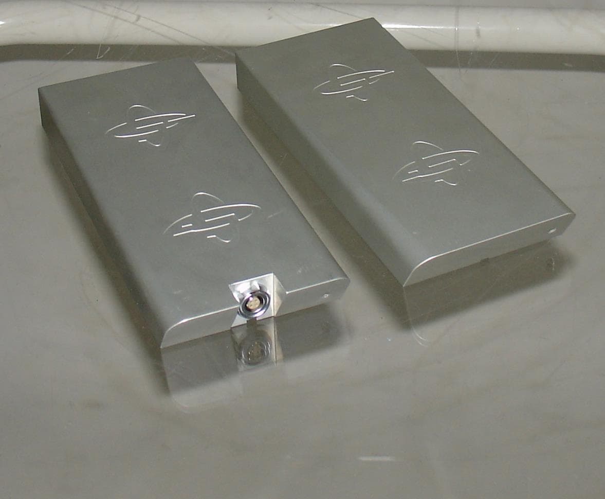
QLA450MHZHDR
May 17, 2014Ground Penetrating Radar
Equipment Class
UWB - Ultra Wideband Transmitter
QLA160MHZHDR
Jan 23, 2014Ground Penetrating Radar
Equipment Class
UWB - Ultra Wideband Transmitter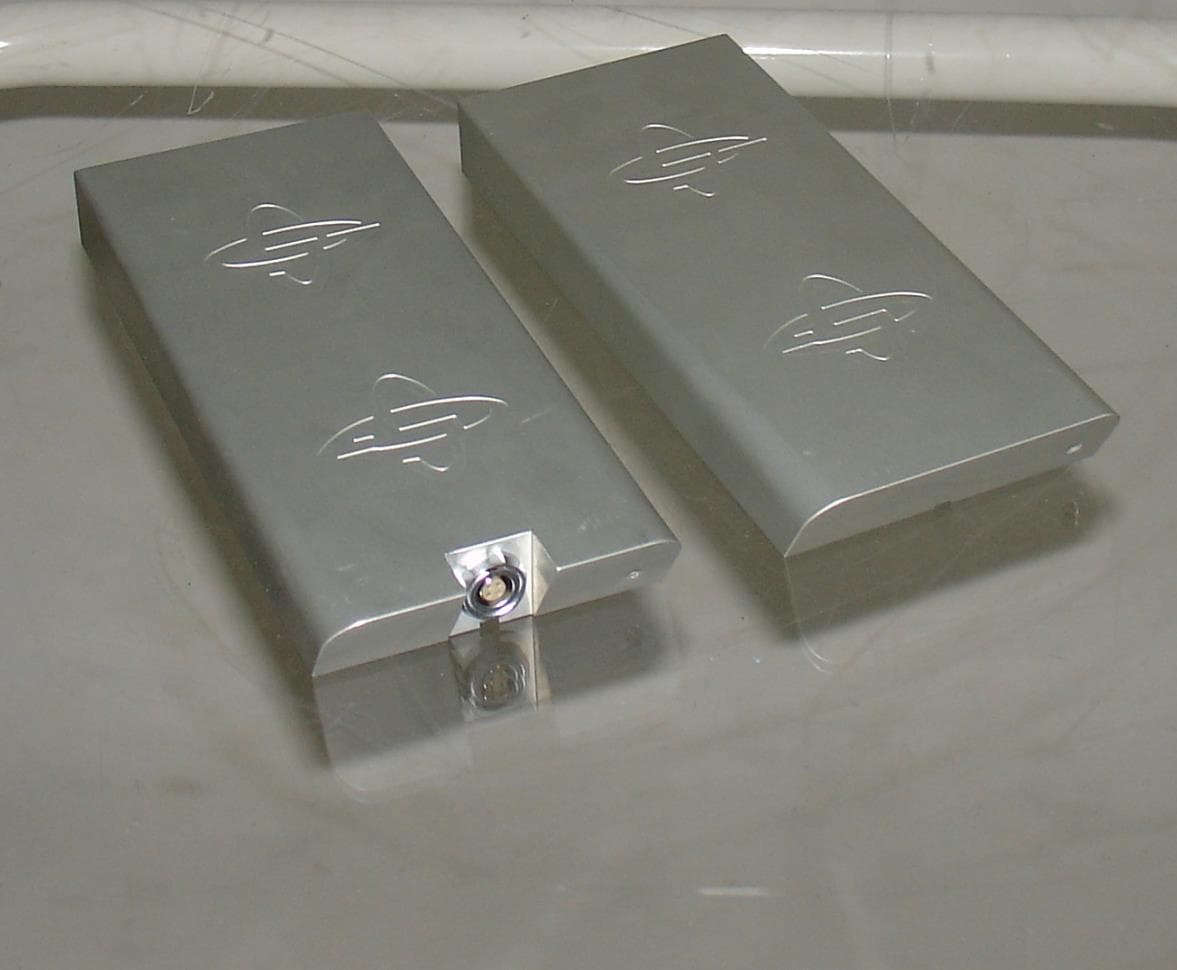
QLA750MHZHDR
Jan 23, 2014Ground Penetrating Radar
Equipment Class
UWB - Ultra Wideband Transmitter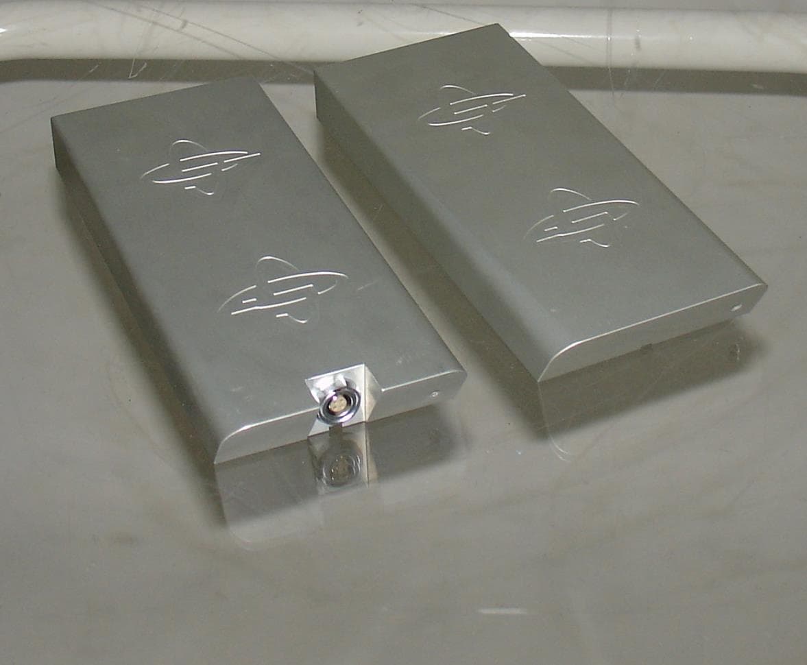
QLA80MHZHDR
Jan 23, 2014Ground Penetrating Radar
Equipment Class
UWB - Ultra Wideband Transmitter