QN5XT400-RTire Pressure Monitor System
Felio Electronics (M) Sdn Bhd
Click to zoom
Application Details
- Equipment Class
- CYY - Communications Receiver used w/Pt 15 Transmitter
- Date of Grant
- Oct 22, 2002
- Application Purpose
- Original Equipment
- Date of Application
- Oct 22, 2002
- Equipment Note
- Tire Pressure Monitor System
- Frequency Range
- 433.92000000 - 433.92000000
- Country
- Malaysia
Documents & Files
Document Text
Text extracted from the exhibit documents filed with the FCC. Open a document above to read the original.
Users Manual
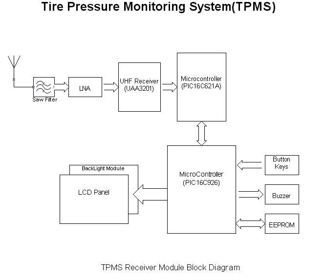
08-09-01-001-0 Tire Pressure Monitoring System OWNER’S MANUAL An advance tire pressure monitoring system that gives you the maximum control TABLE OF CONTENTS 1. Notices ................................................................................................... FCC Notice System Scope of Use and Warnings System Installation and Usage Reacting To Alerts Use of Chemicals Page 2 1. Technical Specifications ........................................................................... Sensor/Transmitter Module Display/Receiver Module Page 3 2. Components Part Code List ........................................................................ Page 4 3. Getting Started ......................................................................................... How it works Handling Alerts Page 5 4. Sensor/Transmitter Module ......................................................................... Installation Tools Required Installing Sensor/Transmitter on a wheel Page 6 5. Display/Receiver Module ............................................................................ Installation Wiring Diagram Function Keys/Buttons Explanation Programming Manual Threshold Setting ............................................. Display Mode ................................................................................ Rotation Mode Normal Mode Sensor ID Exchange Mode .............................................................. Sensor ID Learning Mode (Replacing Display Module or Sensor) ............ Page 7 Page 8 Page 9 Page 10 Page 11 6. Troubleshooting ....................................................................................... Page 12 7. Appendix Glossary ................................................................................ Page 12 8. Annex .............................................................................................. Page 13 The manufacturer reserves the right to change the contents of this manual at any time without prior notice. The information contained in this manual is proprietary and must not be reproduced without prior consent from the manufacturer. Page 1 NOTICE FCC Notice This device complies with Part 15 of the FCC Rules. Operation is subject to the following two conditions: (1) this device may not cause harmful interference, and (2) this device must accept any interference received, including interference that may cause undesired operation. This equipment has been tested and found to comply with the limits for a Class B digital device, pursuant to Part 15 of the FCC Rules. These limits are designed to provide reasonable protection against harmful interference in a residential installation. This equipment generates, uses and can radiate radio frequency energy and, if not installed and used in accordance with the instructions, may cause harmful interference to radio communications. However, there is no guarantee that interference will not occur in a particular installation. If this equipment does cause harmful interference to radio or television reception, which can be determined by turning the equipment off and on, the user is encouraged to try to correct the interference by one or more of the following measures: • Reorient or relocate the receiving antenna. • Increase the separation between the equipment and receiver. • Connect the equipment into an outlet on a circuit different from that to which the receiver is connected. Caution : Any changes or modifications in construction of this device which are not expressly approved by the party responsible for compliance could void the user’s authority to operate the equipment. System Scope of Use and Warnings Tire Pressure Monitoring System (TPMS) This system is a sensing device designed to measure and display tire operation and/or activate an alert to the driver when pressure and temperature irregularities are detected. It is the responsibility of the driver to react promptly and with discretion to alerts. Abnormal tire inflation pressure should be corrected at the earliest opportunity. System Installation and Usage Use of the TPMS requires that it has been properly installed by qualified personnel according to the instructions here. This system is suitable for use in passenger car, SUV and 4X4 tires up to maximum cold inflation pressure of 500 kPa (or 73 psi). Reacting to Alerts When an alert or warning is received, reduce vehicle speed and proceed to a safe stop location where the tire can be inspected and/or serviced. The low-pressure alert indicates that the air pressure has dropped to a selected minimum and a high- temperature alert indicates that the temperature of the tire content has surpassed the threshold value set. Use of Chemical Temporary resealing or re-inflation products containing internal sealants or propellants in any tire assembly may adversely affect the operation of the Sensor/Transmitter. Page 2 1. TECHNICAL SPECIFICATION Sensor / Transmitter Module Operating Temperature Range -40°C to +125°C Operating Humidity 100% Weight 48 gram Size 101 mm x 26 mm x 44 mm Battery Life (Projected) 5 years in normal use Transmitting Frequency 433.92 MHz Transmitter Activation Pressure change Table 1 Display/Receiver Module Power Supply 9 ~ 15 V DC Current Consumption 30mA nominal, 80mA during alert @ 12V DC. Operating Temperature Range -40°C to +85°C Weight 146 gram Receiving Frequency 433.92 MHz Monitored Temperature Range -40 ~ 125°C (-104 ~ 257°F) Monitored Pressure Range 0 ~ 500 kPa (Accuracy: ± 10 kPa) 0 ~ 73 psi (Accuracy: ± 1.5 psi) Table 2 Page 3 2. Component Part Code List After unpacking, ensure that all the parts listed below are available. Should any part(s) is/are found missing, please return to your dealer and get a complete replacement set. Item Description Part Code Quantity 1 TPMS DISPLAY MODULE ASSY 70-08-01-001-0 1 2 TPMS SENSOR MODULE ASSY#1 70-08-01-002-0 1 3 TPMS SENSOR MODULE ASSY#2 70-08-01-003-0 1 4 TPMS SENSOR MODULE ASSY#3 70-08-01-004-0 1 5 TPMS SENSOR MODULE ASSY#4 70-08…
Text truncated - open the document above for the full version.
External Photos
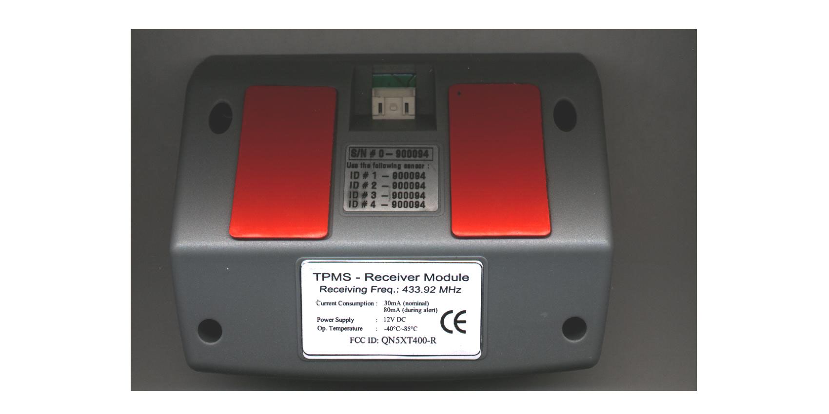
(External Photos)
Internal Photos
(Internal Photos)
Test Report
KTL Korea Testing Laboratory Page 1 of 8 TEST REPORT This test report only responds to the tested sample and shall not be reproduced except in full without written approval of the Korea Testing Laboratory. Tested and reported by Reviewed by Jeong-Min Kim , Senior Engineer Hee-Soo Kim , Telecommunication Team Manager KOREA TESTING LABORATORY FG101-01-02-00 222-13, Guro-Dong Guro-Gu Seoul Korea 152-053 http://www.ktl.re.kr Ref. Report No. 02-341-035-02 Name and address of the applicant Felio Group(M) Sdn. Bhd. Lot 5, Jalan Gudang 16/9 Seksyen 16, Shah Alam, 40200 Malaysia Standard / Test regulation FCC Part 15, Subpart B Test result Pass Incoming date : October 01, 2002 Test item(s) ; Communication Receiver used with Part 15 Tx (Tire Pressure Monitoring System) Model/type ref. ; TPMS Manufacturer ; Felio Group(M) Sdn. Bhd. Additional information ; -Required Authorization : Certification -FCC ID. : QN5XT400-R -Note : Test report(Certification) of Transmitter portion of this System is issued on Ref. Report No. 02-341-035-01. Test date : October 08, 2002 Issue date : October 16, 2002 Ref. Report No. 02 - 341 – 035 - 02 Page 2 of 8 Korea Testing Laboratory Telecommunication Team 222-13, Guro3-dong, Guro-gu, Seoul Korea 152-848 TABLE OF CONTENTS I. GENERAL INFORMATION 3 1. Grantee’s Name and Mailing Address 2. Manufacturer's Name and Mailing Address 3. Equipment Descriptions 4. Rules and Regulations 5. Measuring Procedure 6. Place of Measurement 7. Date of Measurement . GENERAL REQUIREMENTS OF THE EUT 4 1. Labeling Requirement (Section 15.19) 2. Information to User (Sections 15.21) 3. Special Accessories (Section 15.27) . RADIATED EMISSION MEASUREMENT (Section 15.109) 5 1. Test Procedure 2. Photograph for the test configuration 3. Sample Calculation 4. Measurement Data . TEST EQUIPMENTS USED FOR MEASUREMENT 8 Ref. Report No. 02 - 341 – 035 - 02 Page 3 of 8 Korea Testing Laboratory Telecommunication Team 222-13, Guro3-dong, Guro-gu, Seoul Korea 152-848 . GENERAL INFORMATION 1. Grantee’s Name and : Felio Group(M) Sdn. Bhd. Mailing Address Lot 5, Jalan Gudang 16/9 Seksyen 16, Shah Alam, 40200 Malaysia 2. Manufacturer's Name and : Felio Group(M) Sdn. Bhd. Mailing Address Lot 5, Jalan Gudang 16/9 Seksyen 16, Shah Alam, 40200 Malaysia 3. Equipment Descriptions 3.1 Operating Frequency : 433.92 MHz 3.2 Detect Method : Superheterodyne Detector 3.3 Local Oscillator : Local Osc. Frequency = Operating Frequency – 0.5 MHz (IF) 3.4 Power Supply : DC 12 V (Car Battery) 4. Rules and Regulations : FCC Part 15, Subpart B 5. Measuring Procedure : ANSI C63.4-1992 6. Place of Measurement : Absorber-lined Room (KTL) 7. Date of Measurement 7.1 Conducted Emission : Not Applicable 7.2 Radiated Emission : October 08, 2002 Ref. Report No. 02 - 341 – 035 - 02 Page 4 of 8 Korea Testing Laboratory Telecommunication Team 222-13, Guro3-dong, Guro-gu, Seoul Korea 152-848 . GENERAL REQUIREMENTS OF THE EUT 1. Labeling Requirement (Section 15.19) This device complies with Part 15 of the FCC Rules. Operation is subject to the following two conditions: (1) this device may not cause harmful interface, and (2) this device must accept any interference received, including interference that may cause undesired operation. 1.1 Location of Label : User’s Guide Manual 1.2 How Applied : Printed 2. Information to User (Section 15.21) The following or similar statements were provided in the manual for user instruction. Please refer page 2 of the attached manual for details. CAUTION : Any changes or modifications in construction of this device which are not expressly approved by the party responsible for compliance could void the user's authority to operate the equipment. 3. Special Accessories (Section 15.27) 3.1 Were the special Accessories provided? [ ] yes, [ x ] no 3.2 If yes, details for the special accessories are as follows : 3.3 If yes, were the appropriate instructions provided on the first page of the text concerned with the device? [ ] yes, [ ] no 3.4 Are these accessories provided of the type which can be readily obtained from multiple retail outlets ? [ ] yes, [ ] no And therefore does the manual specify what additional components or accessories are required to used in order to comply with the Rules? [ ] yes, [ ] no Ref. Report No. 02 - 341 – 035 - 02 Page 5 of 8 Korea Testing Laboratory Telecommunication Team 222-13, Guro3-dong, Guro-gu, Seoul Korea 152-848 . RADIATED EMISSION MEASUREMENT (Section 15.109) 1. Test Procedure 1.1 Preliminary Testing for Reference Preliminary testing was performed in a KTL absorber-lined room to determine the emission characteristics of the EUT. The EUT was placed on the wooden table which has dimensions of 0.8 meters in height, 1 meter in length and 1.5 meters in width. Receiving antenna (Biconical antenna : 30 to 300 MHz, Log-periodic antenna : 200 to 1000 MHz or Horn Antenna : 1 to 18 GHz) was placed at the distance of 1 meter from the EUT. An attempt was made to maximize the emission level with the various configurations of the EUT while rotating the table and varying antenna height. Emission levels from the EUT with various configurations were examined on a Spectrum Analyzer connected with a RF amplifier and graphed by a plotter. 1.2 Final Radiated Emission Test at an Absorber-Lined Room The final measurement of radiated field strength was carried out in a KTL Absorber-Lined Room that was listed up at FCC according to the "Radiated Emissions Testing" procedure specified by ANSI C63.4. Based on the test results in preliminary test, measurement was made in same test set up and configuration which produced maximum emission level. Receiving antenna was installed at 3-meter distance from the EUT, and was connected to an EMI receiver or spectrum analyzer with a RF amplifier. Turntable was rotated through 360 degrees and receiving antenna height was varied from 1 to 4 meters above the ground plane to read maximum emission level. If necessary, the radiated emission measurements could be performed …
Text truncated - open the document above for the full version.
Test Setup Photos
Ref. Report No. 02 - 341 – 035 - 02 Page 7 of 8 Korea Testing Laboratory Telecommunication Team 222-13, Guro3-dong, Guro-gu, Seoul Korea 152-848 2. Photograph for the test configuration 3. Sample Calculation The emission level measured in decibels above one microvolt (dB) was converted into microvolt per meter (/m) as shown in following sample calculation. For example : Measured Value at 866.68 MHz 12.4 dB/m + Antenna Factor 23.0 dB + Cable Loss 5.3 dB Preamplifier 0.0 dB Distance Correction Factor * 0.0 dB = Radiated Emission 40.7 dB/m ( = 108.4 /m) * Extrapolated from the measured distance to the specified distance by an inverse linear distance extrapolation.
Contact Information
Applicant
Tek Heng Ong(General Manager)
Test Firm
Korea Testing LaboratoryJeong-Min Kim
Technical Specifications
| # | Rule Parts | Frequency Range | Power Output |
|---|---|---|---|
| 1 | 15B | 433.92 MHz - 433.92 MHz | - |
Other Applications from Felio Electronics (M) Sdn Bhd

QN5XT400-T
Oct 22, 2002Tire Pressure Monitoring System
Equipment Class
DSC - Part 15 Security/Remote Control Transmitter