QNA-SL2000Tank Unit
Raven Industries, Inc.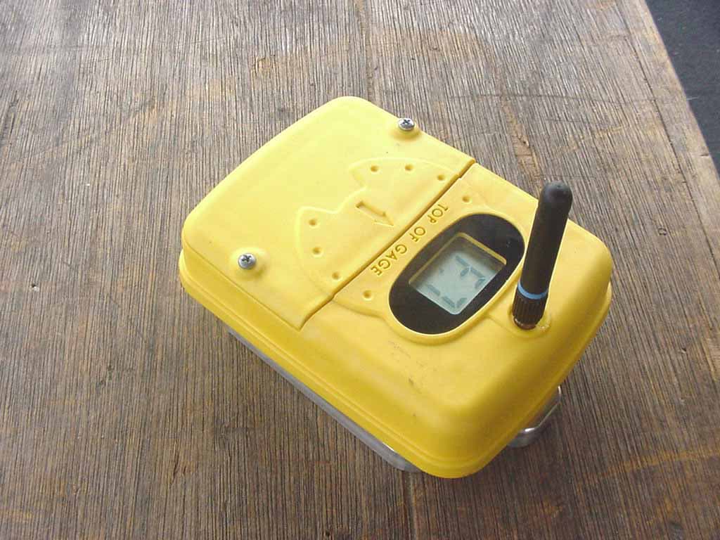
Click to zoom
Application Details
- Equipment Class
- DSC - Part 15 Security/Remote Control Transmitter
- Date of Grant
- Oct 02, 2002
- Application Purpose
- Original Equipment
- Date of Application
- Oct 02, 2002
- Equipment Note
- Tank Unit
- Frequency Range
- 418.00000000 - 418.00000000
- Company
- Raven Industries, Inc.
- Country
- United States
Documents & Files
Document Text
Text extracted from the exhibit documents filed with the FCC. Open a document above to read the original.
Users Manual
Rev. A Date 10/02 Smartlink ™ Anhydrous Ammonia Fluid Monitoring System Owner’s Guide Page - 2 – Fluent Systems – SmartLink System Table of Contents Instruction to the User Page 2 Introduction Page 3 Features / System Components Page 4 Cab Unit Quick Reference Guide Page 8 Using the Smartlink (tm) System Page 9 Troubleshooting Page 14 Instruction to the User This equipment has been tested and found to comply with the limits for a class B digital device, pursuant to part 15 of the FCC rules. These limits are designed to provide reasonable protection against harmful interference in a residential installation. This equipment generates uses and can radiate radio frequency energy and if not installed and used in accordance with the instructions, may cause harmful interference to radio communications. However, there is not guarantee that interference will not occur in a particular installation. If this equipment does cause harmful interference to radio or television reception which can be determined b turning the equipment off and on, the user is encouraged to try to correct the interference by one or more of the following measures: Reorient or relocate the receiving antenna Increase the separation between the equipment and the receiver. Consult dealer or an experienced radio/TV technician for help. This equipment has been certified to comply with the limits for a class B computing device, pursuant to FCC rules. In order to maintain compliance with FCC regulations, shielded cables must be used with the equipment. Operation with non-approved equipment or unshielded cables is likely to result in interference with radio and TV reception. The user is cautioned that changes and modifications made to the equipment without the approval of the manufacturer could void the user’s authority to operate this equipment. Page - 3 – Fluent Systems – SmartLink System Introduction Congratulations on your purchase of the Smartlink (tm) monitoring system from Fluent Systems. Smartlink (tm) is an innovative electronic system that allows you to continuously monitor the application of anhydrous ammonia fertilizer from within the tractor cab. This patent-pending product utilizes modern RF and electromagnetic sensing technologies in a novel and revolutionary way and dramatically improves the process by which anhydrous ammonia is applied to your field. The Smartlink (tm) is a two-module system composed of a tank module that sits atop the field tank and a cab module that is positioned within the tractor cab. The tank module can be set directly on top of the existing fluid level gage with no modifications required to the tank and no tools necessary. The tank module continuously monitors the fluid level within the field tank and then sends it in a wireless fashion to the display module mounted inside the tractor cab. The display module receives the signal from the tank module, decodes the information and displays fluid level to the user via a liquid crystal display. The cab module allows the farmer to quickly input implement and tank size. This information is processed along with groundspeed data from the tractor to output other useful information to the farmer including application rate per acre, time remaining until tank is empty and a "tank-empty" audible alert. The Smartlink (tm) is a capable agricultural aid that provides convenience and added functionality not present today. The Smartlink (tm) is a useful addition to the existing process of applying anhydrous ammonia to farmland worldwide. It solves the difficult task of measuring fluid in a hazardous environment while remaining completely safe to use. Information gathered by the Smartlink (tm) can be used during application to increase operator efficiency and decrease common problems associated with the current method. It also accurately reports fertilizer application rate per acre, which adds greatly to the farmer's information. The Smartlink (tm) is a system that includes one display module and one tank module, along with necessary groundspeed interface, power cable and cab mounting hardware. The product carries a one-year limited warranty. Page - 4 – Fluent Systems – SmartLink System Features and System Components Your Smartlink (tm) System comes complete and ready to use with the following components: Cab Module Tank Module Windshield Adaptor Ground Speed Adaptor 12 V Cigarette Lighter Adaptor Carrying Case Page - 5 – Fluent Systems – SmartLink System Operation: General Operating Conditions: Tank Unit Cab Unit Maximum Temperature XX degrees F XX Minimum Temperature XX degrees F XX The Smartlink (tm) system has been designed for durable, robust operation and should withstand years of use. The unit does contain precision electronic components and should be treated carefully to ensure trouble free operation. Do not expose the either Cab or Tank unit to excessive heat or cold. The Tank unit has been designed to be water and dust resistant. Prolonged exposure to driving rain, excessive sleet or snow should be avoided. If the Tank unit will not be used for extended periods of time, the unit should be removed from a tank and stored inside it’s protective case. The batteries should be removed to prevent leakage. Do not leave the Cab Unit in excessive heat or cold or direct sunlight for prolonged periods of time. The user should be aware that extreme temperatures inside tractor cabs can cause damage to the Cab Unit. Avoid exposing the Cab Unit to extremely dusty conditions. Avoid dropping either the Cab or Tank unit. While both units have been designed for shock and vibration resistance, sensitive electronic components can be damaged due to excessive shock or vibration. Tank Unit Batteries The Tank unit runs on three AA sized batteries. Do not mix old batteries with new batteries. Do not use different types of batteries together. There is no need to turn the tank unit on or off. Under normal use, the tank unit will run three months before needing to change batteries. If…
Text truncated - open the document above for the full version.
Block Diagram
Low Power Micro with A/D TI MSP430F133-149 Internal 1MHz-8MHz RC Oscillator 3V LDO linear regulator TPS79030 DC 3 AA batteries DC 2.7V Reset IC TC54 DC 2 digit LCD Transmitter Linx TXM-433-LC 418 MHz Antenna & Connector Linx RPSMA ANT-418-CW-RH Magnetic sensor system 1/2 Amp 10uS pulses DC DC 418 MHz Smartlink Tank Unit (Magnetic Sensor & Transmitter) DCI Project 1279 9/30/02 saw 418MHz Block Diagram 64Hz 1.6Hz LCD drivers 74HC86 XOR 64Hz 5V Inverter REG710 1 MHz 2405 baud 1202.5Hz DC 32,768 crystal 32.768KHz 1-10HzDC DC
Cover Letter(s)
114 OLINDA DRIVE • •• • BREA, CALIFORNIA 92823 • •• • (714) 579-0500 • •• • FAX (714) 579-1850 September 30, 2002 Compatible Electronics TCB 114 Olinda Drive Brea, CA 92823 Subject: Request for Certification of the Fluent Systems, LLC. Tank Unit Model: SL2000 FCC ID: QNA-SL2000 Gentlemen: We have enclosed a package for the certification of the Fluent Systems, LLC Tank Unit Model: SL2000. We have enclosed the completed Form 731 with the applicable exhibits. If you have any questions or need any additional information, please give me a call at (714) 579-0500. Sincerely, Kyle Fujimoto Test Engineer
ID Label/Location Info
Tank Unit Label Size And Location Labels adhered to bottom of case Label Dimensions SmartLink System Tank Unit – SL2000Serial Number:xxxxxxxSoftware Build Version:xxxxxxxx FCC ID: QNA-SL2000 This device complies with Part 15 of the FCC Rules. Operation is subject to the following two conditions:(1)This device may not cause harmful interference and (2) This device must accept any interference received, including interference that may cause undesired operation Tank Unit Label Size And Location Labels adhered to bottom of case Label Dimensions SmartLink System Tank Unit – SL2000Serial Number:xxxxxxxSoftware Build Version:xxxxxxxx FCC ID: QNA-SL2000 This device complies with Part 15 of the FCC Rules. Operation is subject to the following two conditions:(1)This device may not cause harmful interference and (2) This device must accept any interference received, including interference that may cause undesired operation
Test Report
Report Number: B20927A1 FCC Part 15 Subpart B and FCC Section 15.231(e) Test Report Tank Unit Model: SL2000 114 OLINDA DRIVE, BREA, CALIFORNIA 92823 PHONE: (714) 579-0500 FAX: (714) 579-1850 Page 1 of 1 7 FCC PART 15, SUBPART B and C TEST REPORT for TANK UNIT MODEL: SL2000 Prepared for FLUENT SYSTEMS, LLC 5325 WALL STREET MADISON, WISCONSIN 53718 Prepared by:_____________________ KYLE FUJIMOTO Approved by:____________________ MICHAEL CHRISTENSEN COMPATIBLE ELECTRONICS INC. 114 OLINDA DRIVE BREA, CALIFORNIA 92823 (714) 579-0500 DATE: SEPTEMBER 30, 2002 REPORT APPENDICES TOTAL BODY A B C D E PAGES 17 2 2 2 10 18 51 This report shall not be reproduced except in full, without the written approval of Compatible Electronics. Report Number: B20927A1 FCC Part 15 Subpart B and FCC Section 15.231(e) Test Report Tank Unit Model: SL2000 114 OLINDA DRIVE, BREA, CALIFORNIA 92823 PHONE: (714) 579-0500 FAX: (714) 579-1850 Page 2 of 1 7 TABLE OF CONTENTS Section / Title PAGE GENERAL REPORT SUMMARY 4 SUMMARY OF TEST RESULTS 4 1. PURPOSE 5 2. ADMINISTRATIVE DATA 6 2.1 Location of Testing 6 2.2 Traceability Statement 6 2.3 Cognizant Personnel 6 2.4 Date Test Sample was Received 6 2.5 Disposition of the Test Sample 6 2.6 Abbreviations and Acronyms 6 3. APPLICABLE DOCUMENTS 7 4. Description of Test Configuration 8 4.1 Description of Test Configuration - EMI 8 4.1.1 Cable Construction and Termination 9 5. LISTS OF EUT, ACCESSORIES AND TEST EQUIPMENT 10 5.1 EUT and Accessory List 10 5.2 EMI Test Equipment 11 6. TEST SITE DESCRIPTION 12 6.1 Test Facility Description 12 6.2 EUT Mounting, Bonding and Grounding 12 7. Test Procedures 13 7.1 Radiated Emissions (Spurious and Harmonics) Test 13 7.2 Bandwidth of the Fundamental 15 7.3 Plot Showing the Time between Transmissions 16 8. CONCLUSIONS 17 Report Number: B20927A1 FCC Part 15 Subpart B and FCC Section 15.231(e) Test Report Tank Unit Model: SL2000 114 OLINDA DRIVE, BREA, CALIFORNIA 92823 PHONE: (714) 579-0500 FAX: (714) 579-1850 Page 3 of 1 7 LIST OF APPENDICES APPENDIX TITLE A Laboratory Recognitions B Modifications to the EUT C Additional Models Covered Under This Report D Diagrams, Charts, and Photos • Test Setup Diagrams • Radiated Emissions Photos • Antenna and Effective Gain Factors E Data Sheets LIST OF FIGURES FIGURE TITLE 1 Plot Map And Layout of Test Site Report Number: B20927A1 FCC Part 15 Subpart B and FCC Section 15.231(e) Test Report Tank Unit Model: SL2000 114 OLINDA DRIVE, BREA, CALIFORNIA 92823 PHONE: (714) 579-0500 FAX: (714) 579-1850 Page 4 of 1 7 GENERAL REPORT SUMMARY This electromagnetic emission test report is generated by Compatible Electronics Inc., which is an independent testing and consulting firm. The test report is based on testing performed by Compatible Electronics personnel according to the measurement procedures described in the test specifications given below and in the "Test Procedures" section of this report. The measurement data and conclusions appearing herein relate only to the sample tested and this report may not be reproduced without the written permission of Compatible Electronics, unless done so in full. This report must not be used to claim product endorsement by NVLAP or any other agency of the U.S. Government. Device Tested: Tank Unit Model: SL2000 S/N: N/A Product Description: See Expository Statement. Modifications: The EUT was not modified during the testing. Manufacturer: Fluent Systems, LLC 5325 Wall Street Madison, Wisconsin 53718 Test Date: September 17, 2002 Test Specifications : EMI requirements CFR Title 47, Part 15 Subpart B; and Subpart C, Sections 15.205, 15.209, and 15.231(e) Test Procedure: ANSI C63.4: 1992 Test Deviations: The test procedure was not deviated from during the testing. SUMMARY OF TEST RESULTS TEST DESCRIPTION RESULTS 1 Conducted RF Emissions, 450 kHz - 30 MHz This test was not performed because the EUT operates on battery power only and cannot be plugged into the AC public mains. 2 Radiated RF Emissions, 10 kHz - 4300 MHz Complies with the Class B limits of CFR Title 47, Part 15, Subpart B; and Subpart C, sections 15.205, 15.209, and 15.231(e). Report Number: B20927A1 FCC Part 15 Subpart B and FCC Section 15.231(e) Test Report Tank Unit Model: SL2000 114 OLINDA DRIVE, BREA, CALIFORNIA 92823 PHONE: (714) 579-0500 FAX: (714) 579-1850 Page 5 of 1 77 1. PURPOSE This document is a qualification test report based on the Electromagnetic Interference (EMI) tests performed on the Tank Unit Model: SL2000. The EMI measurements were performed according to the measurement procedure described in ANSI C63.4: 1992. The tests were performed in order to determine whether the electromagnetic emissions from the equipment under test, referred to as EUT hereafter, are within the Class B specification limits defined by CFR Title 47, Part 15, Subpart B; and Subpart C, sections 15.205, 15.209, and 15.231(e). Report Number: B20927A1 FCC Part 15 Subpart B and FCC Section 15.231(e) Test Report Tank Unit Model: SL2000 114 OLINDA DRIVE, BREA, CALIFORNIA 92823 PHONE: (714) 579-0500 FAX: (714) 579-1850 Page 6 of 1 7 2. ADMINISTRATIVE DATA 2.1 Location of Testing The EMI tests described herein were performed at the test facility of Compatible Electronics, 114 Olinda Drive, Brea, California 92823. 2.2 Traceability Statement The calibration certificates of all test equipment used during the test are on file at the location of the test. The calibration is traceable to the National Institute of Standards and Technology (NIST) . 2.3 Cognizant Personnel Fluent Systems, LLC Jaume Villanueva Chief Operations Officer Compatible Electronics, Inc. Kyle Fujimoto Test Engineer Michael Christensen Test Engineer 2.4 Date Test Sample was Received The test sample was received on September 16, 2002. 2.5 Disposition of the Test Sample The sample has not been returned to Fluent Systems, LLC as of September 30, 2002. 2.6 Abbreviations and Acronyms The following abbreviations and acronyms may be used in this document. RF Radio Frequency EMI…
Text truncated - open the document above for the full version.
Contact Information
Applicant
Dan Rykhus(Vice President and Flow Control Div Gen Mgr)
[email protected]605-335-0272
Technical Contact
Compatible ElectronicsKyle Fujimoto
714-579-0500
114 Olinda Drive · Brea, California · United States
Test Firm
Compatible ElectronicsScott McCutchan
714-579-0500Fax: 714-579-1850
Technical Specifications
| # | Rule Parts | Frequency Range | Power Output |
|---|---|---|---|
| 1 | 15.231(e) | 418 MHz - 418 MHz | - |