QNEM760REMAVIATION TRANSCEIVER
PS Engineering, Incorporated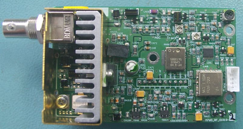
Click to zoom
Application Details
- Equipment Class
- TNB - Licensed Non-Broadcast Station Transmitter
- Date of Grant
- May 03, 2011
- Application Purpose
- Original Equipment
- Date of Application
- May 03, 2011
- Equipment Note
- AVIATION TRANSCEIVER
- Frequency Range
- 118.00000000 - 136.97500000
- Company
- PS Engineering, Incorporated
- Country
- United States
Documents & Files
Document Text
Text extracted from the exhibit documents filed with the FCC. Open a document above to read the original.
Users Manual
Microair Avionics M760REM User Manual M760REM-USER 01R1.doc Page 1 of 12 10 th March 2011 M760REM-01-0 Airband VHF Transceiver User Manual Microair Avionics M760REM User Manual M760REM-USER 01R1.doc Page 2 of 12 10 th March 2011 Table of Contents 1.0 INTRODUCTION............................................................................................ 3 2.0 DEVELOPMENT HISTORY......................................................................... 3 3.0 INSTALLATION ............................................................................................. 4 3.1 Mounting .................................................................................................................. 4 3.2 Connection ............................................................................................................... 4 3.3 Location ...................................................................................................................4 3.4 Antenna ....................................................................................................................4 3.5 Wiring ......................................................................................................................5 3.6 Wiring Diagram ....................................................................................................... 5 3.7 Technical Drawing ................................................................................................... 6 4.0 TRANSCEIVER CONTROL ......................................................................... 7 4.1 RS232 Serial Data Interface..................................................................................... 7 4.1.1 Transceiver Function ................................................................................................... 7 4.1.2 Transceiver Status ........................................................................................................8 4.1.3 Set Squelch Level ........................................................................................................8 4.1.4 Report Squelch Level................................................................................................... 9 4.2 PTT Line ................................................................................................................ 10 4.3 Microphone Audio Input........................................................................................ 10 4.4 Headphone Audio Output ...................................................................................... 10 5.0 SPECIFICATION.......................................................................................... 11 Microair Avionics M760REM User Manual M760REM-USER 01R1.doc Page 3 of 12 10 th March 2011 1.0 Introduction The M760REM-USER describes installation, data interface, and operation of the transceiver. The M760REM-USER is a controlled document and may not be chnaged without the prior consent of Miroair Avionics. 2.0 Development History The M760REM is a development of the Microair M760 Airband Transceiver. This development replaces the human interface display assembly, with a serial data interface. The M760REM retains the serial data SL30 interface from the M760, for control over the active frequency, standby frequency, and dual monitor mode. The serial data interface replaces all controls normally accessible from the display assembly, with serial command codes. A third party control unit can use these commands to maintain full control and operation of the M760REM. Existing controls and interfaces such as the microphone audio in, headphone audio out, and PTT line remain unchanged from the original M760. Microair Avionics M760REM User Manual M760REM-USER 01R1.doc Page 4 of 12 10 th March 2011 3.0 Installation The M760REM has no display or human interface control. The unit can fixed to any appropriate aircraft structure which is inside the aircraft cabin. The M760REM should be located clear of air vents or cabin heating, and should not be subject to outside weather. For pressurised aircraft, the M760REM shall be located inside the pressure hull, in a temperature controlled space. 3.1 Mounting The M760REM has mounting flanges with four M4 x 10 (5/32” x 3/8”) slotted holes. 3.2 Connection Electrical connection is made using a Sub- D15 connector, which is held in place using thumbscres or lock bolts (4-40). The RF connection is made using a 50 ohm BNC connector. 3.3 Location The location of the M760REM should consider access to the adjustment trimpots for microphone gain, sidetone level, and headphone aduio level. Consideration should also be given to the connector and cable bending radius for the wiring harness and coax cable. 3.4 Antenna The M760REM is compatible with any TSO C37d/C38d compliant Airband antenna. The coaxial cable shall be 50 ohm (eg RG58/RG400). Microair Avionics M760REM User Manual M760REM-USER 01R1.doc Page 5 of 12 10 th March 2011 3.5 Wiring Microair recommends the use of the Mil-Spec wiring for all lines, and installaed in accordance with the techniques described in FAA AC43-13-2A Pin Line Wire 1 Pilot Microphone Electret or amplified dynamic 2 RS232 RX RS232 TX (data in) 5 RS232 TX RS232 RX (data out) 7 PTT <3Vdc to activate 9 Power +14V (do not exceed 16Vdc) 10 Power +14V (do not exceed 16Vdc) 11 Ground Aircraft Ground 12 Ground Aircraft Ground 14 Headphone Line level Audio (typical 100mW into 600Ohms) BNC Aerial RG58C/U 50 ohm Coaxial Cable All wiring is connected by soldering to the DB15 connector. Inspect the solder cup side of the DB15 carefully to determine the pin numbering. 3.6 Wiring Diagram Microair Avionics M760REM User Manual M760REM-USER 01R1.doc Page 6 of 12 10 th March 2011 3.7 Technical Drawing Microair Avionics M760REM User Manual M760REM-USER 01R1.doc Page 7 of 12 10 th March 2011 4.0 Transceiver Control The M760REM is fully controlled via the following connections: RS232 Serial Data Interface PTT line Microphone Audio In…
Text truncated - open the document above for the full version.
Users Manual
Microair Avionics M760REM Declaration of Design Performance M760REM-DDP 01R3.doc Page 1 of 21 18 th April 2011 M760REM-01-0 Airband VHF Transceiver Declaration of Design Performance Microair Avionics M760REM Declaration of Design Performance M760REM-DDP 01R3.doc Page 2 of 21 18 th April 2011 Table of Contents 1.0 INTRODUCTION............................................................................................ 3 2.0 DEVELOPMENT HISTORY......................................................................... 3 3.0 PRODUCT DESCRIPTION ........................................................................... 4 3.1 AF Board........................................................................................................ 4 3.2 RF Board ........................................................................................................ 5 3.3 Micro Board ................................................................................................... 6 3.4 Chassis ........................................................................................................... 7 4.0 FREQUENCY TUNING ................................................................................. 8 5.0 PC EMULATION ............................................................................................ 8 6.0 TRANSMITTER FUNCTION ....................................................................... 9 7.0 RECEIVER FUNCTION .............................................................................. 12 8.0 SPECIFICATION.......................................................................................... 13 9.0 NON-INTERFERENCE TESTING............................................................. 14 9.1 Table of Testing ........................................................................................... 14 9.2 Test Equipment ............................................................................................ 14 10.0 SUPPORTING DATA ................................................................................... 15 11.0 TECHNICAL DRAWING ............................................................................ 21 Microair Avionics M760REM Declaration of Design Performance M760REM-DDP 01R3.doc Page 3 of 21 18 th April 2011 1.0 Introduction The M760REM-DDP lists and describes the performance of the transceiver. Where necessary, the performance items are referenced to RTCA standards, which define the performance items and the method of measurement. All performance measurements for this document are made at Microair’s factory at Bundaberg Australia, under standard environmental conditions. 2.0 Development History The M760REM is a development of the Microair M760 Airband Transceiver. This development replaces the human interface display assembly, with a serial data interface. The M760REM retains the serial data SL30 interface from the M760, for control over the active frequency, standby frequency, and dual monitor mode. The serial data interface replaces all controls normally accessible from the display assembly, with serial command codes. A third party control unit can use these commands to maintain full control and operation of the M760REM. Existing controls and interfaces such as the microphone audio in, headphone audio out, and PTT line remain unchanged from the original M760. Microair Avionics M760REM Declaration of Design Performance M760REM-DDP 01R3.doc Page 4 of 21 18 th April 2011 3.0 Product Description The M760REM consist of three major sub assemblies: AF Board (p/n M760_AF_01R18-6A) RF Board (p/n M760_RF_01R19-2) Micro Board (p/n M760UAV_MICRO_01R1-0) 3.1 AF Board The AF (Audio Frequency) board holds the following systems: IF filter, three stage strip, & Detector AGC Mute Microphone input and audio compression PTT switching Audio PA DB15 electrical connector RS232 line driver 9.5V regulator 5V regulator Microair Avionics M760REM Declaration of Design Performance M760REM-DDP 01R3.doc Page 5 of 21 18 th April 2011 3.2 RF Board The RF (Radio Frequency) board holds the following systems: TCXO PLL/VCO Receiver front end & LP filter Transmitter & PA Modulator Microair Avionics M760REM Declaration of Design Performance M760REM-DDP 01R3.doc Page 6 of 21 18 th April 2011 3.3 Micro Board The Micro Board holds the following systems: Microcontroller Squelch adjust Headphone audio adjust 5V regulator Microair Avionics M760REM Declaration of Design Performance M760REM-DDP 01R3.doc Page 7 of 21 18 th April 2011 3.4 Chassis The M760REM has a sheet aluminium chassis with a divider plate in the centre, to which the AF and RF boards are fixed. The MICRO board is fixed to the front of the divider plate. Harnessing from the MICRO board connects the AF and RF boards. The chassis is completed by a base plate, front plate, back plate, and top cover. The top cover features mounting flanges, to facilitate installation. Microair Avionics M760REM Declaration of Design Performance M760REM-DDP 01R3.doc Page 8 of 21 18 th April 2011 4.0 Frequency Tuning The M760REM frequency control is via the SL30 command interface. Upon receipt of a valid “set active” or set standby” command, the microcontroller will decode the frequency value and pass it to the PLL via an SPI interface. The PLL will set the control volts for the VCO, which in turn provides the signal source to the transceiver. 5.0 PC Emulation Microair provides a PC application to emulate a standard M760 display. The emulator interfaces to the M760REM via the PC’s serial port, and used the SL30 command set. All functions can be tested, and the application provides a communications window to confirm the command traffic. Microair Avionics M760REM Declaration of Design Performance M760REM-DDP 01R3.doc Page 9 of 21 18 th April 2011 6.0 Transmitter Function M760 Transmitter Figure 1 The above figure shows the basic layout of the transmitter in block diagram. The VHF fundamental frequency is generated by…
Text truncated - open the document above for the full version.
ID Label/Location Info
Location sketch of Serial tag/FCC ID M760REM
ID Label/Location Info
M760REM Serial No. Label 1038 Material: Black, printed 1 color on 3M #7983 Silver computer imprintable Mylar (0.010") and die cut. Continuous feed roll or sheet 9800 Martel Road Lenoir City TN 37772 Phone (865) 988-9800 Fax (865) 988-6619 Serial No. Part Number 050-760-6746 M760 REM VHF COM FCC ID: QNEM760REM 2.25 in 2.25 in
Internal Photos
Microair Avionics M760REM Declaration of Design Performance M760REM-DDP 01R2 Page 5 of 18 11 th March 2011 3.2 AF Board The AF (Audio Frequency) board holds the following systems: • IF filter, three stage strip, & Detector • AGC • Mute • Microphone input and audio compression • PTT switching • Audio PA • DB15 electrical connector • RS232 line driver • 9.5V regulator • 5V regulator Microair Avionics M760REM Declaration of Design Performance M760REM-DDP 01R2 Page 6 of 18 11 th March 2011 3.3 RF Board The RF (Radio Frequency) board hold the following systems: • TCXO • PLL/VCO • Receiver front end & LP filter • Transmitter & PA • Modulator Microair Avionics M760REM Declaration of Design Performance M760REM-DDP 01R2 Page 7 of 18 11 th March 2011 3.4 Micro Board The Micro Board holds the fllowing systems: • Microcontroller • Squelch adjust • Headphone audio adjust • 5V regulator Microair Avionics M760REM Declaration of Design Performance M760REM-DDP 01R2 Page 8 of 18 11 th March 2011 3.5 Chassis The M760REM has a sheet aluminium chassis with a dividor plate in the centre, to which the AF and RF boards are fixed. The MICRO board is fixed to the front of the divider plate. Harnessing from the MICRO board connects the AF and RF boards. The chassis is completed by a base plate, front plate, back plate, and top cover. The top cover features mounting flanges, to facilitate installation.
Operational Description
Microair Avionics M760REM Declaration of Design Performance M760REM-DDP 01R2 Page 8 of 18 11 th March 2011 3.5 Chassis The M760REM has a sheet aluminium chassis with a dividor plate in the centre, to which the AF and RF boards are fixed. The MICRO board is fixed to the front of the divider plate. Harnessing from the MICRO board connects the AF and RF boards. The chassis is completed by a base plate, front plate, back plate, and top cover. The top cover features mounting flanges, to facilitate installation.
Parts List/Tune Up Info
Operating Procedure for M760REM Radio Document: 002-760-0150 Date: 03-15-11 Revision: New Page 1 of 3 Operating Procedure for M760UAV VHF COM radio Equipment setup: Required equipment: 14 VDC power supply, 0-3 A PC with RS232 port, 9-pin connector Test harness provided by PS Engineering Microair Control panel software provided by PS Engineering Installing the Terminal Program File: Extract file M760 Test Panel PC App.zip to local hard drive Launch the file, m760UAV.exe, from PC App folder. Using the Terminal Program: With the EUT connector to the computer RS-232 port, and after power applied, click the Connect button. Operating Procedure for M760REM Radio Document: 002-760-0150 Date: 03-15-11 Revision: New Page 2 of 3 The display will read the last used frequencies in the radio. The M760REM can now be controlled using the terminal program. Frequency control (1) Four preset frequencies are available in the Frequency Control section (band ends and mid band) that enter into the active frequency, plus a direct access frequency entry that can be entered into either active or standby frequency register. Frequencies are entered with the decimal point, and all significant digits for 25 kHz channels. NOTE: The EUT only transmits in the frequency range 118.00 to 136.975 MHz. Frequencies bwtween 108.00 and 117.95 are receive only in the aeronautical navigation band. Receiver squelch control (2) The receiver squelch threshold is adjusted in the “Squelch Function” section. The receiver squelch can be instantly set at the ends and middle of the range, in increment of a single step (single chevron) or in increments of eight steps (double chevrons). Operating Procedure for M760REM Radio Document: 002-760-0150 Date: 03-15-11 Revision: New Page 3 of 3 NOTE: The higher the squelch number, the smaller the RF signal is required to open the squelch. Max (127) is the squelch completely open. Miscellaneous (3) Misc Functions are for troubleshooting and debugging, and not used for control. Receiver volume control (4) Unit receiver volume is factory set to maximum, and screwdriver adjustable through the hole on chassis. Turn clockwise to decrease volume. Shutdown procedure Remove power from the EUT, and exit the terminal program.
Parts List/Tune Up Info
Microair Avionics M760REM Declaration of Design Performance M760REM-DDP 01R2 Page 9 of 18 11 th March 2011 4.0 Frequency Tuning The M760REM frequency control is via the SL30 command intrface. Upon receipt of a valid “set active” or set standby” command, the microcontoller will decode the frewquency value and pass it to the PLL via an SPI interface. The PLL will set the control volts for the VCO, which in turn provides the signal source to the transceiver. 5.0 PC Emulation Microair provides a PC application to emulate a standard M760 display. The emulator interfaces to the M760REM via the PC’s serial port, and used the SL30 command set. All functions can be tested, and the application provides a communications window to confirm the command traffic. 6.0 Receiver Function The M760REM has a superhetrodyne receiver with an IF frequency of 10.7MHz. The receiver is “high side” tuned (eg for 127.000MHz the VCO is tuned to 137.700MHz. The M760REM is also fitted with a dual monitor function, where the PLL is rapidly switched between the active and standby frequencies. If carrier is detected, the switching process is locked to receive that signal. When carrier is no longer present the M760REM will return to rapid switching between the active and standby. If the M760 is receiving on the standby frequency, it will regularly resample the active for the presence of carrier. If carrier is detected on the active, the M760REM will switch back to the active frequency. The M760 can be pout into or out of dual monitor by setting the applicable bit in either the set active or set standby commands.
Test Report
FCC PART 87 TEST REPORT APPLICANT PS Engineering, Inc. 9800 Martel Road Lenoir City TN 37772 USA FCC ID QNEM760REM MODEL NUMBER M760REM PRODUCT DESCRIPTION VHF COM RADIO DATE SAMPLE RECEIVED 3/22/2011 DATE TESTED 4/4/2011 TESTED BY Nam Nguyen APPROVED BY Mario R. de Aranzeta TIMCO REPORT NO. 557AUT11TestReport.doc TEST RESULTS PASS FAIL THE ATTACHED REPORT SHALL NOT BE REPRODUCED EXCEPT IN FULL WITHOUT THE WRITTEN APPROVAL OF TIMCO ENGINEERING, INC. 849 NW STATE ROAD 45 NEWBERRY, FL 32669 USA PH: 888.472.2424 OR 352.472.5500 FAX: 352.472.2030 EMAIL: [email protected] HTTP://WWW.TIMCOENGR.COM Certificate # 0955-01 Applicant: PS Engineering, Inc. FCC ID: QNEM760REM Report: P\PS Engr\557AUT11\557AUT11TestReport.doc Page 2 of 17 TABLE OF CONTENTS STATEMENT OF COMPLIANCE .................................................................................3 GENERAL INFORMATION .........................................................................................4 DUT Specification ........................................................... 4 EMC EQUIPMENT LIST ............................................................................................6 TEST PROCEDURE ..................................................................................................7 RF POWER OUTPUT .................................................................................................8 MODULATION CHARACTERISTICS ...........................................................................9 VOICE MODULATED COMMUNICATION EQUIPMENT ............................................. 10 FIELD STRENGTH OF SPURIOUS EMISSIONS ........................................................ 15 FREQUENCY STABILITY ......................................................................................... 16 POWER LINE CONDUCTED INTERFERENCE .......................................................... 17 Applicant: PS Engineering, Inc. FCC ID: QNEM760REM Report: P\PS Engr\557AUT11\557AUT11TestReport.doc Page 3 of 17 STATEMENT OF COMPLIANCE This equipment has been tested in accordance with the standards identified in the referenced test report. To the best of my knowledge and belief, these tests were performed using the measurement procedures described in this report and demonstrate that the equipment complies with the appropriate standards. No modifications were made to the equipment during testing in order to demonstrate compliance with these standards. I attest that the necessary measurements were made by me or under my supervision, at Timco Engineering, Inc. located at 849 N.W. State Road 45, Newberry, Florida 32669 USA. Authorized by: Mario R. de Aranzeta Signature: Function: Engineer Date: 4/14/2011 Applicant: PS Engineering, Inc. FCC ID: QNEM760REM Report: P\PS Engr\557AUT11\557AUT11TestReport.doc Page 4 of 17 GENERAL INFORMATION DUT Specification The test results relate only to the items tested. DUT Description VHF COM RADIO FCC ID QNEM760REM Model Number M760REM Operating Frequency TX: 118.000 – 136.975 MHz RX: 108.000 – 139.975 MHz No. of Channels 760 channels – 25 kHz spacing Modulation AM DUT Power Source 110–120Vac/50– 60Hz DC Power 14 Vdc Battery Operated Exclusively Test Item Prototype Pre-Production Production Type of Equipment Fixed Mobile Portable Applicant: PS Engineering, Inc. FCC ID: QNEM760REM Report: P\PS Engr\557AUT11\557AUT11TestReport.doc Page 5 of 17 Test Facility: The test sites used by Timco Engineering Inc. for collecting radiated and conducted emission data are located at 849 NW State Road 45 Newberry, FL 32669 USA. Test Condition: The DUT was tested in the laboratory in an environment with normal temperature and humidity. The temperature was 26ºC with a relative humidity of 50%. Modification to the DUT: No modification was made to the DUT during testing. Test Exercise (e.g. software description, test signal, etc.): The DUT was placed in continuous transmit mode of operation. Applicable Standards: TIA 603 FCC CFR 47 Part 87 Part 2.1033(c) (4) Type of Emission: 6K00A3E Bn = 2M M = 3000 Bn = 2(3000) = 6k The authorized bandwidth is 25 kHz. Part 2.1033(c)(8) DC Voltages and Current into Final Amplifier: POWER INPUT: FINAL AMPLIFIER ONLY INPUT POWER – HIGH: (14 Vdc)(1.65A) = 23.10 Watts Applicant: PS Engineering, Inc. FCC ID: QNEM760REM Report: P\PS Engr\557AUT11\557AUT11TestReport.doc Page 6 of 17 EMC EQUIPMENT LIST Device Manufacturer Model Serial Number Cal/Char Date Due Date 3-Meter Semi- Anechoic Chamber Panashield N/A N/A Listed 3/10/10 3/10/12 AC Voltmeter HP 400FL 2213A14499 CAL 3/23/09 3/23/12 Antenna: Dipole Kit Electro- Metrics TDA-30/1-4 153 CHAR 6/10/09 6/10/11 Frequency Counter HP 5385A 3242A07460 CAL 5/26/09 5/26/11 Hygro- Thermometer Extech 445703 0602 CAL 1/30/09 1/30/12 Modulation Analyzer HP 8901A 3435A06868 CAL 5/26/09 5/26/11 Digital Multimeter Fluke FLUKE-77-3 79510405 CAL 5/18/09 5/18/11 Analyzer Tan Tower Preamplifier HP 8449B-H02 3008A00372 CAL 11/21/09 11/21/11 Analyzer Tan Tower Quasi- Peak Adapter HP 85650A 3303A01690 CAL 11/22/09 11/22/11 Analyzer Tan Tower RF Preselector HP 85685A 3221A01400 CAL 11/21/09 11/21/11 Analyzer Tan Tower Spectrum Analyzer HP 8566B Opt 462 3138A07786 3144A20661 CAL 11/24/09 11/24/11 Temperature Chamber Tenney Engineering TTRC 11717-7 CHAR 4/25/10 4/25/12 Applicant: PS Engineering, Inc. FCC ID: QNEM760REM Report: P\PS Engr\557AUT11\557AUT11TestReport.doc Page 7 of 17 TEST PROCEDURE Power Line Conducted Interference: The procedure used was TIA 603 using a 50uH LISN. Both lines were observed with the UUT transmitting. The bandwidth of the spectrum analyzer was 10 kHz with an appropriate sweep speed. Bandwidth 20 dB: The measurements were made with the spectrum analyzer's resolution bandwidth (RBW) = 1 MHz and the video bandwidth (VBW) = 3 MHz and the span set as shown on plot. Power Output: The RF power output was measured at the antenna feed point using a peak power meter. Antenna Conducted Emissions: The RBW = 100 kHz, VBW = 300 kHz and the span set …
Text truncated - open the document above for the full version.
Contact Information
Applicant
Gary Picou(Vice President of Technical Services)
Test Firm
Timco Engineering, Inc.Bruno Clavier
Technical Specifications
| # | Rule Parts | Frequency Range | Power Output | Emission | Tolerance |
|---|---|---|---|---|---|
| 1 | 87 | 118 MHz - 136.975 MHz | 5 W | 6K00A3E | 0.4000000000 ppm |