QNS24GWVSAVSWireless Surveillance System
VECCOM GBE LTD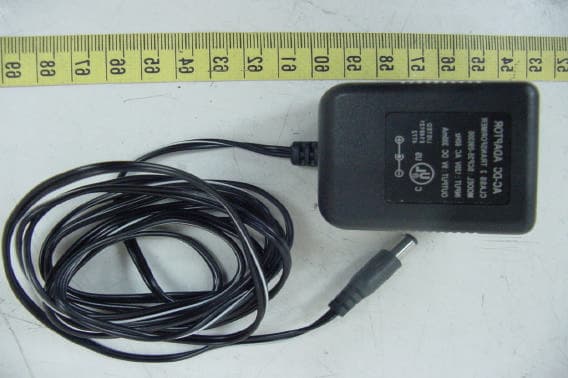
Click to zoom
Application Details
- Equipment Class
- DXX - Part 15 Low Power Communication Device Transmitter
- Date of Grant
- Jun 02, 2003
- Application Purpose
- Original Equipment
- Date of Application
- Jun 02, 2003
- Equipment Note
- Wireless Surveillance System
- Frequency Range
- 2412.00000000 - 2472.00000000
- Company
- VECCOM GBE LTD
- Country
- Taiwan
Documents & Files
Document Text
Text extracted from the exhibit documents filed with the FCC. Open a document above to read the original.
Users Manual
H. Specifications 18 Transm itter: O u t p ut Level O p erat i ng F r equency B a nd M o d u latio n V i deo I n p u t Level A u di o In p u t Level V i deo I n p u t Im p e dance A u di o In p u t Im p e dance P o wer cons um pt i o n D i m e nsi o ns We i g h t Rec e iv er: O u t p ut Level No ise Figu re P o wer C o n s um pt i o n Rem o te Co ntro l Tran sm itte r Freq uency D i m e nsi o ns We i g h t 90 dB m i crovolts/m eter at 3 meters (com pl y wi t h F C C , B ZT) 2. 4 t o 2. 48 3 5 GHZ FM (vi d eo and audio) 1 V p - p @ 75 oh m 1V p-p @ 6 0 0 ohm 75 o h m s 60 0 o h m s 9 Vd c, 12 0 m A 12 .8 X 9. 7 X 5 . 0 cm (5.0 X 3 . 8 X 2. 0 i n ches) 2 66g ( 9 .4 oun ces) 1 vol t p-p ( v i d eo), 1 vo l t p-p (audi o) 3. 5 dB 9 Vd c, 30 0 m A 43 3. 9 2 M H z (PAL) , 41 8M H z ( N TSC)* 12 .8 X 9. 7 X 5 . 0 cm (5.0 X 3 . 8 X 2. 0 i n ches) 2 66g ( 9 .4 oun ces) * F o r M o del M 3 0 1 o n l y All specific a tions are subject to ch an g e with ou t no tice. 1 □ Important-Safety Precautions . To pre v ent fire or shock ha zard, do not expose this product to rain or m o isture. Do not use near a bath tub, wash bow l, kitche n sink, or laundry tub, in a wet baseme nt, or ne a r a swimmi ng pool. . To avoid el ec tric a l shock, do not open this product. . This product should be opera te d using only the power supply included with it or provided as an a c c e ssory. . Do not overload wall out lets a nd extension cords as this can result in the risk of fire or e l e c t r ic shock. . Re fer servicing to quali fi ed per s onnel only. □ Note: This equipment has been t e sted a nd found to comply wit h the li mits f o r CTC, FCC and CE EMC directive. These li mits are designed to provide reasonable protect ion against har m ful inter f er enc e in a residential insta lla ti on. This equipment generat e s, uses and c a n radiat e r a dio frequency energy a nd, if not ins t all e d and used in ac corda n ce with the instruction, ma y c a use har m ful int e rferenc e to radio communic ations. However, there is no guarant ee t h at interfere nce wil l not occur in a particular install a tion. I f t h is equipme n t does cause har m ful interference to radio or tel e vision reception, which can be det e r m ined by turning the equipment off and on, the user is encourage to try to correct the i n terference by one or m o r e of the following measures: . Reorient or relocate th e receiving antenn a. . Increase the separation between the equipm ent and receiver. . Connect the equipment into an ou tlet on a circuit different from that to which the re ceiver is connected. . Consult the d e al er or an experi enced radio/TV technician for he l p . Caution: Changes or m o difi ca t ons not expressly approved by the party responsible for complianc e co uld void the user' s authority to operat e the equipme n t. ! G. Troubleshooting, Ca r e a n d ma i n te na nce Table of Contents Please r e ad th i s own e r's man u a l c a r e fu lly a n d fo ll o w th e step s d e scrib e d in it . If y o u still h a v e d i fficu lties, con s u lt t h e fo llowing tab l e. It wi ll g u i d e yo u t h o ugh th e m o st co m m on pro b l e m s and t h ei r s o l u t i o n s . A. Introduction to 2.4 GHz Wire less Video Sender...................................3 B. Descripti on of Box Contents..................................................................4 C. Panel Controls and F eatur es...................................................................5 D. Setting up Syste m ...................................................................................9 Conne cti ng the System Trans m it t e r to: . VCR.................................................................................................10 . Satell i t e Rec e iver or Laser Disc Player...........................................11 Conne ct ing the Syste m Rec e iver to: . Televi sion ( or Vi deo Monitor ).....................................................12 . VCR................................................................................................13 E. Orient ing Syste m for Opti mal Per f or mance........................................14 F. U s ing The Re mot e Control Feature.....................................................16 G. Troubleshooting & Care and Mai n tenanc e.........................................17 H. Specific a tions......................................................................................18 Problem No pi ct ure or s o u n d Interf er en ce: Noi s y pi ct ure or audi o Re m o te co n t ro l ex ten d e r does no t w o rk (M 20 1 and M 3 01 o n l y ) Po ss ib le s o l u ti o n s . C h eck the power on/ off switches on the transm itter a n d re ce i v er . C h eck power swi t c hes o n t h e rem o te TV and vi deo sou r ce (VCR, laser d i sc p l ay e r , satellit e r e c e iv er, e c t.) . Mak e su r e po w e r p l ug s ar e pu sh ed all th e w a y in . C h eck all c a b le co n n ectio ns . Adju st rec e i v er an d tran smitter an t e n n a o r ien t atio n (see sectio n on "Orien tin g Un it s fo r Op tim al Per f o r man c e" in t h is Man u a l) . Sel ect a di ffer e nt channel by pu sh i n g t h e channel sele cto r b u t t o n on bo th tran sm itte r an d re c e iv er so th at t h e channels match . If usi n g a m i crowav e oven, t u rn i t off . R e m ove m i crowave oven from pat h bet w een t r ansm i t t er a n d re ce i v er. . C h eck th e p a th b e twe e n the tr an sm itte r a n d th e au di o / vi deo so urce and cl ear any obs t r uct i o n s . . C h eck to see if the IR window on t h e front of t h e tran sm itter is b l o c k e d . Mak e su re IR ex ten d e r is pro p e rly ro tated in th e A/V eq ui pm ent y o u wi s h t o cont rol (see sect i on o n "Usi ng t h e Rem o te Con t rol Featu r e " in t h is m a n u al) C l ean t h e out si de pl ast i c pack agi ng wi t h a so ft cl ot h l i g h t l y m o i s t e ned wi t h m i l d soap an d water. Never use any abr a si ve scouri n g p o w der o…
Text truncated - open the document above for the full version.
Users Manual
CAUTION RISK OF ELECTRIC SHOCK. DO NOT OPEN. CAUTION: TO REDUCE THE RISK OF ELECTRIC SHOCK, DO NOT REMOVE COVER (OR BACK). NOUSER-SERVICEABLE PARTS INSIDE. REFER SERVICING TO QUALIFIED SERVICE PERSONNEL. Explanation of two Symbols The lightning flash with arrowhead symbol, within an equilateral triangle, is intended to alert the user to the presence of uninsulated "dangerous voltage" within the product's enclosure that may be of sufficient magnitude to constitute a risk of electric shock to persons. The exclamation point within an equilateral triangle is intended to alert the user to the presence of important operating and maintenance-(servicing) instructions in the literature accompanying the appliance. THE GRAPHIC SYMBOLS WITH SUPPLEMENTAL MARKING ARE ON THE BOTTOM OF THE SYSTEM WARNINGTo prevent fire or shock hazard, do not expose this appliance to rain, water, or wet locations. Do not insert any metallic object through the ventilation grills. Important-Safety Precautions n To prevent fire or shock hazard, do not expose this product to rain or moisture. Do not use near a bathtub, washbowl, kitchen sink, or laundry tub, in a wet basement, or near a swimming pool. n To avoid electrical shock, do not open this product. n This product should be operated using only the power supply included with it or provided as an accessory. n Do not overload wall outlets and extension cords as this can result in the risk of fire or electric shock. n Refer servicing to qualified personnel only. IMPORTANT SAFEGUARDS All the safety and operating instructions should be read before the appliance is operated and retained for future reference. 1.HEED WARNINGS - All warnings on the appliance and in the operating instructions should be adhered to. 2.FOLLOW INSTRUCTIONS - All operating instructions should be followed. 3.WATER AND MOISTURE - Do not use this video product near water - for example, a bathtub, washbowl, kitchen sink, laundry tub or swimming pool, or in a wet basement. 4.POWER SOURCES - This product should be operated only from the type of power source indicated on the marking label. 5.OVERLOADING - Do not overload outlets and extension cords, which can result in a risk of fire or electric shock. 6.SERVICING - Do not attempt to service this product yourself. Opening or removing covers may expose you to dangerous voltage or other hazards. Refer all servicing or repairs to qualified service personnel. 7.DAMAGE REQUIRING SERVICE - Unplug this product from the wall outlet and refer servicing or repairs to qualified service personnel under the following conditions: a. When the power supply cord or plug is damaged. b. If liquid has been spilled or objects have fallen into the product. c. If the product has been exposed to rain or water. d. If the product does not operate normally by following the operating instructions. e. Adjust only those controls that are covered by the operating instructions. f. If the product has been dropped or the cabinet has been damaged. g. When the product exhibits a distinct change in performance. 8.REPLACEMENT PARTS - When replacement parts are required, be sure the service technician has used replacement parts that are specified by the manufacturer or have the same characteristics as the original part. Unauthorized substitutions may result in fire, electric shock, or other hazards. 9.SAFETY CHECK - Upon completion of any service or repairs to this video product, ask the service technician to perform safety checks to determine if the video product is in proper operating condition. 10.An appliance and cart combination should be moved with care. Do not place this equipment on an unstable cart, stand, or table. The equipment may fall, causing serious injury to a child or adult, and serious damage to the equipment. Wall or shelf mounting should follow the manufacturer's instructions and should be done with a mounting kit approved by the manufacturer. Note: This equipment has been tested and found to comply with the limits for CTC, FCC and CE EMC directive. These limits are designed to provide reasonable protection against harmful interference in a residential installation. This equipment generates, uses and can radiate radio frequency energy and, if not installed and used in accordance with the instruction, may cause harmful interference to radio communications. However, there is no guarantee that interference will not occur in a particular installation. If this equipment does cause harmful interference to radio or television reception, which can be determined by turning the equipment off and on, the user is encourage to try to correct the interference by one or more of the following measures: n Reorient or relocate the receiving antenna. n Increase the separation between the equipment and receiver. n Connect the equipment into an outlet on a circuit different from that to which the receiver is connected. n Consult the dealer or an experienced radio/TV technician for help. GENERAL DESCRIPTION Congratulations on your purchase of the AVLink 2.4 GHz Wireless Audio & Video Sender System. The AVLink lets you enjoy satellite TV, DVD, VCR, CDs and many other audio/video media in another room - without purchasing additional components, moving existing components or running cables. The 2.4 GHz Wireless Audio/Video Transmitter uses wide-band FM to transmit true discrete stereo audio signals. The circular polarized high-gain directional transmitting and receiving antennas minimize interference, resulting in maximum clarity and a signal range of up to 300 feet (NTSC) 750 feet (PAL). PACKAGE CONTENTS Check to make sure that all of the items shown as below are included with your system. If something is missing, please contact your dealer as soon as possible. 2.4GHz Wireless Transmitter X 1 pcs 2.4GHz Wireless Receiver X 1 pcs ü 120VAC to 9 VDC/300mA AC Power Adapters (FCC) or ü 230VAC to 9 VDC/300mA AC Power Adapters (CE) X 2 pcs or ü RCA-to-RCA A/V Cable (NTSC) or ü RCA-to-SCART A/V Cable (PAL) …
Text truncated - open the document above for the full version.
External Photos
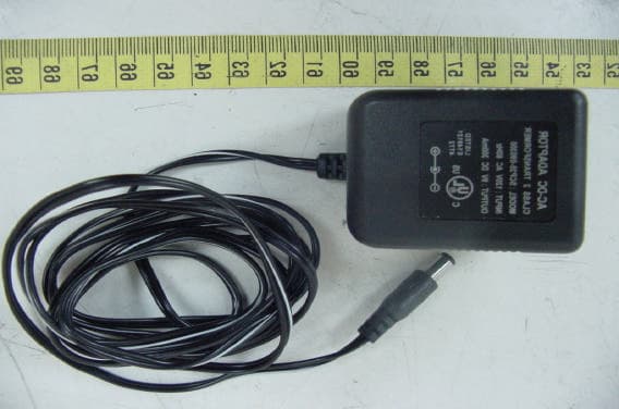
ETC Report No. : ET91R-12-048-01 Sheet 1 of 11 Sheet FCC ID. : QNS24GWVSAVS Rev. No 1.0 CONSTRUCTED PHOTOS of EUT 1. Top View of Transmitter 2. Bottom View of Transmitter ETC Report No. : ET91R-12-048-01 Sheet 2 of 11 Sheet FCC ID. : QNS24GWVSAVS Rev. No 1.0 CONSTRUCTED PHOTOS of EUT 3. Top View of Transmitter ETC Report No. : ET91R-12-048-01 Sheet 3 of 11 Sheet FCC ID. : QNS24GWVSAVS Rev. No 1.0 CONSTRUCTED PHOTOS of EUT 4. Side View of Transmitter 5. Side View of Transmitter ETC Report No. : ET91R-12-048-01 Sheet 4 of 11 Sheet FCC ID. : QNS24GWVSAVS Rev. No 1.0 CONSTRUCTED PHOTOS of EUT 6. Front View of Transmitter 7. Rear View of Transmitter ETC Report No. : ET91R-12-048-01 Sheet 9 of 11 Sheet FCC ID. : QNS24GWVSAVS Rev. No 1.0 CONSTRUCTED PHOTOS of EUT 16. Front View of Adaptor 17. Rear View of Adaptor
ID Label/Location Info
Rear View
Internal Photos
ETC Report No. : ET91R-12-048-01 Sheet 5 of 11 Sheet FCC ID. : QNS24GWVSAVS Rev. No 1.0 CONSTRUCTED PHOTOS of EUT 8. Internal View of Transmitter 9. Internal View of Transmitter ETC Report No. : ET91R-12-048-01 Sheet 6 of 11 Sheet FCC ID. : QNS24GWVSAVS Rev. No 1.0 CONSTRUCTED PHOTOS of EUT 10. Component View of Transmitter 11. Solder View of Main PCB (Transmitter) ETC Report No. : ET91R-12-048-01 Sheet 7 of 11 Sheet FCC ID. : QNS24GWVSAVS Rev. No 1.0 CONSTRUCTED PHOTOS of EUT 12. Component View of Main PCB (Transmitter) 13. Solder View of Main PCB (Transmitter) ETC Report No. : ET91R-12-048-01 Sheet 8 of 11 Sheet FCC ID. : QNS24GWVSAVS Rev. No 1.0 CONSTRUCTED PHOTOS of EUT 14. Component View of Main PCB (Transmitter) 15. Solder View of Main PCB (Transmitter) ETC Report No. : ET91R-12-048-01 Sheet 10 of 11 Sheet FCC ID. : QNS24GWVSAVS Rev. No 1.0 CONSTRUCTED PHOTOS of EUT 18. Internal View of Adaptor 19. Component View of Adaptor’s PCB ETC Report No. : ET91R-12-048-01 Sheet 11 of 11 Sheet FCC ID. : QNS24GWVSAVS Rev. No 1.0 CONSTRUCTED PHOTOS of EUT 20. Component View of Adaptor’s PCB 21. Solder View of Adaptor’s PCB
Operational Description
This 2.4GHz Wireless Audio & Video Sender lets you enjoy satellite TV, DVD, VCR, CDs and many other audio/video media in another room - without purchasing additional components, moving existing components or running cables. The 2.4 GHz Wireless Audio/Video Transmitter uses wide-band FM to transmit true discrete stereo audio signals. The circular polarized high-gain directional transmitting and receiving antennas minimize interference, resulting in maximum clarity and a signal range of up to 300 feet (NTSC) 750 feet (PAL). The system not only allows you to send crisp audio/video from one area to another, it also gives you the ability to control the source using your existing remote control device. It converts the infrared (IR) signal emitted by your remote control to a radio frequency (RF) signal in UHF band at the Receiver and sends it back to the Transmitter where the RF signal is converted back to the original IR signal and beamed to the audio/video source.
Test Report
Rev. No 1.0 FCC Part 15 EMI TEST REPORT of E.U.T. : 2.4GHz Wireless Surveillance System MODEL : M111/ WVS111/ WVS222 FCC ID. : QNS24GWVSAVS for APPLICANT : Veccom GBE LTD. ADDRESS : 3 Tze Chiang 1 Road, Chungli Industrial Park, Tao Yuan Hsien, Taiwan, R.O.C. Test Performed by ELECTRONICS TESTING CENTER, TAIWAN NO. 34, LIN 5 , DING FU TSUN, LINKOU HSIANG, TAIPEI HSIEN, TAIWA, R.O.C. Tel:(02)26023052 Fax:(02)26010910 http://www.etc.org.tw ; e-mail : [email protected] Report Number : ET91R-12-048-01 ETC Report No. : ET91R-12-048-01 FCC ID. : QNS24GWVSAVS Rev. No 1.0 TEST REPORT CERTIFICATION Applicant : Veccom GBE LTD. 3 Tze Chiang 1 Road, Chungli Industrial Park, Tao Yuan Hsien, Taiwan, R.O.C. Manufacturer : Veccom GBE LTD. 3 Tze Chiang 1 Road, Chungli Industrial Park, Tao Yuan Hsien, Taiwan, R.O.C. Description of EUT : a) Type of EUT : 2.4GHz Wireless Surveillance System b) Trade Name : Veccom c) Model No. : M111/ WVS111/ WVS222 d) Power Supply : Adaptor; I/P: 120Vac, 60Hz; O/P: 9Vdc, 300mA e) Frequency Range : 2400MHz-2483.5MHz Regulation Applied : FCC Rules and Regulations Part 15 Subpart C (2002) I HEREBY CERTIFY THAT: The data shown in this report were made in accordance with the procedures given in ANSI C63.4, and the energy emitted by the device was founded to be within the limits applicable. I assume full responsibility for accuracy and completeness of these data. Note: 1. The result of the testing report relate only to the item tested. 2. The testing report shall not be reproduced expect in full, without the written approval of ETC. Issued Date : May 12, 2003 Test Engineer : (Vincent Chang) Approve & Authorized Signer : Will Yauo, Manager EMC Dept. II of ELECTRONICS TESTING CENTER, TAIWAN ETC Report No. : ET91R-12-048-01 FCC ID. : QNS24GWVSAVS Rev. No 1.0 Table of Contents Page 1 GENERAL INFORMATION.......................................................................................................1 1.1 Product Description........................................................................................................................1 1.2 Characteristics of Device................................................................................................................1 1.3 Test Methodology..........................................................................................................................1 1.4 Test Facility....................................................................................................................................1 2 PROVISIONS APPLICABLE.......................................................................................................2 2.1 Definition........................................................................................................................................2 2.2 Requirement for Compliance...........................................................................................................3 2.3 Restricted Bands of Operation........................................................................................................5 2.4 Labeling Requirement.....................................................................................................................5 2.5 User Information............................................................................................................................6 3 SYSTEM TEST CONFIGURATION...........................................................................................7 3.1 Justification.....................................................................................................................................7 3.2 Devices for Tested System.............................................................................................................7 4 RADIATED EMISSION MEASUREMENT..............................................................................8 4.1 Applicable Standard.......................................................................................................................8 4.2 Measurement Procedure.................................................................................................................8 4.3 Measuring Instrument...................................................................................................................10 4.4 Radiated Emission Data................................................................................................................11 4.4.1 Tx Portion................................................................................................................................11 4.4.2 Radiated Emissions in Restricted Bands.....................................................................................14 4.4.2 Rx Portion...............................................................................................................................15 4.4.3 Other Emissions........................................................................................................................16 4.5 Field Strength Calculation.............................................................................................................16 4.6 Photos of Radiation Measuring Setup............................................................................................17 5 CONDUCTED EMISSION MEASUREMENT........................................................................18 5.1 Standard Applicable.....................................................................................................................18 5.2 Measurement Procedure...............................................................................................................18 5.3 Conducted Emission Data.............................................................................................................19 5.3.1 Tx Protion...............................................................................................................................19 5.3.2 Rx Protion..…
Text truncated - open the document above for the full version.
Test Setup Photos
ETC Report No. : ET91R-12-048-01 Sheet 17 of 38 Sheet FCC ID. : QNS24GWVSAVS Rev. No 1.0 4.6 Photos of Radiation Measuring Setup ETC Report No. : ET91R-12-048-01 Sheet 24 of 38 Sheet FCC ID. : QNS24GWVSAVS Rev. No 1.0 5.6 Photos of Conduction Measuring Setup
Contact Information
Applicant
Ben Huang(Executive Vice President)
Test Firm
Electronics Testing Center, TaiwanWinpo Tsai
Technical Specifications
| # | Rule Parts | Frequency Range | Power Output |
|---|---|---|---|
| 1 | 15C | 2.41 GHz - 2.47 GHz | - |
Other Applications from VECCOM GBE LTD
QNS24GWVSAVR
Jun 02, 2003Wireless Surveillance System
Equipment Class
DSC - Part 15 Security/Remote Control Transmitter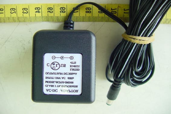
QNSWBM55A88A
Nov 25, 20022.4GHz Wireless Surveillance System
Equipment Class
DXX - Part 15 Low Power Communication Device Transmitter