QORX100LMR UHF Transceiver
TRV Motor Sport, Inc.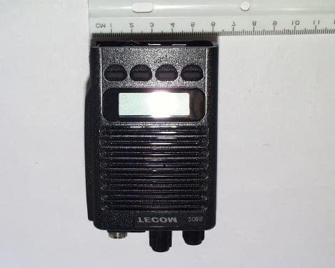
Click to zoom
Application Details
- Equipment Class
- TNF - Licensed Non-Broadcast Transmitter Held to Face
- Date of Grant
- Nov 26, 2002
- Application Purpose
- Original Equipment
- Date of Application
- Nov 26, 2002
- Equipment Note
- LMR UHF Transceiver
- Frequency Range
- 450.00000000 - 470.00000000
- Company
- TRV Motor Sport, Inc.
- Country
- United States
Documents & Files
Document Text
Text extracted from the exhibit documents filed with the FCC. Open a document above to read the original.
Users Manual
ROGERS LABS, INC. TRV Motorsport, Inc. 4405 W. 259th Terrace MODEL: X100 Louisburg, KS 66053 Test #: 020918 FCCID#: QOR X100 Phone/Fax: (913) 837-3214 Test to: FCC Parts 2 and 90 Page 1 of 13 X100BUserman1.doc 11/20/2002 ROGERS LABS, INC. TRV Motorsport, Inc. 4405 W. 259th Terrace MODEL: X100 Louisburg, KS 66053 Test #: 020918 FCCID#: QOR X100 Phone/Fax: (913) 837-3214 Test to: FCC Parts 2 and 90 Page 2 of 13 X100BUserman1.doc 11/20/2002 ROGERS LABS, INC. TRV Motorsport, Inc. 4405 W. 259th Terrace MODEL: X100 Louisburg, KS 66053 Test #: 020918 FCCID#: QOR X100 Phone/Fax: (913) 837-3214 Test to: FCC Parts 2 and 90 Page 3 of 13 X100BUserman1.doc 11/20/2002 ROGERS LABS, INC. TRV Motorsport, Inc. 4405 W. 259th Terrace MODEL: X100 Louisburg, KS 66053 Test #: 020918 FCCID#: QOR X100 Phone/Fax: (913) 837-3214 Test to: FCC Parts 2 and 90 Page 4 of 13 X100BUserman1.doc 11/20/2002 ROGERS LABS, INC. TRV Motorsport, Inc. 4405 W. 259th Terrace MODEL: X100 Louisburg, KS 66053 Test #: 020918 FCCID#: QOR X100 Phone/Fax: (913) 837-3214 Test to: FCC Parts 2 and 90 Page 5 of 13 X100BUserman1.doc 11/20/2002 ROGERS LABS, INC. TRV Motorsport, Inc. 4405 W. 259th Terrace MODEL: X100 Louisburg, KS 66053 Test #: 020918 FCCID#: QOR X100 Phone/Fax: (913) 837-3214 Test to: FCC Parts 2 and 90 Page 6 of 13 X100BUserman1.doc 11/20/2002 ROGERS LABS, INC. TRV Motorsport, Inc. 4405 W. 259th Terrace MODEL: X100 Louisburg, KS 66053 Test #: 020918 FCCID#: QOR X100 Phone/Fax: (913) 837-3214 Test to: FCC Parts 2 and 90 Page 7 of 13 X100BUserman1.doc 11/20/2002 ROGERS LABS, INC. TRV Motorsport, Inc. 4405 W. 259th Terrace MODEL: X100 Louisburg, KS 66053 Test #: 020918 FCCID#: QOR X100 Phone/Fax: (913) 837-3214 Test to: FCC Parts 2 and 90 Page 8 of 13 X100BUserman1.doc 11/20/2002 ROGERS LABS, INC. TRV Motorsport, Inc. 4405 W. 259th Terrace MODEL: X100 Louisburg, KS 66053 Test #: 020918 FCCID#: QOR X100 Phone/Fax: (913) 837-3214 Test to: FCC Parts 2 and 90 Page 9 of 13 X100BUserman1.doc 11/20/2002 ROGERS LABS, INC. TRV Motorsport, Inc. 4405 W. 259th Terrace MODEL: X100 Louisburg, KS 66053 Test #: 020918 FCCID#: QOR X100 Phone/Fax: (913) 837-3214 Test to: FCC Parts 2 and 90 Page 10 of 13 X100BUserman1.doc 11/20/2002 ROGERS LABS, INC. TRV Motorsport, Inc. 4405 W. 259th Terrace MODEL: X100 Louisburg, KS 66053 Test #: 020918 FCCID#: QOR X100 Phone/Fax: (913) 837-3214 Test to: FCC Parts 2 and 90 Page 11 of 13 X100BUserman1.doc 11/20/2002 ROGERS LABS, INC. TRV Motorsport, Inc. 4405 W. 259th Terrace MODEL: X100 Louisburg, KS 66053 Test #: 020918 FCCID#: QOR X100 Phone/Fax: (913) 837-3214 Test to: FCC Parts 2 and 90 Page 12 of 13 X100BUserman1.doc 11/20/2002 ROGERS LABS, INC. TRV Motorsport, Inc. 4405 W. 259th Terrace MODEL: X100 Louisburg, KS 66053 Test #: 020918 FCCID#: QOR X100 Phone/Fax: (913) 837-3214 Test to: FCC Parts 2 and 90 Page 13 of 13 X100BUserman1.doc 11/20/2002 FCC Information THIS DEVICE COMPLIES WITH PART 15 OF THE FCC RULES. OPERATION IS SUBJECT TO THE CONDITION THAT THIS DEVICE DOS NOT CAUSE HARMFUL INTERFERENCE. MODIFICATIONS OR CHANGES NOT EXPRESSLY APPROVED BY THE MANUFACTURER COULD VOID THE USER’S AUTHORITY TO OPERATE THE EQUIPMENT. IMPORTANT NOTE: To maintain compliance with the FCC's RF exposure guidelines, hold the transmitter and antenna at least 1 inch (2.5 centimeters) from your face and speak in a normal voice, with the antenna pointed up and away from the face. If you wear, the handset on your body while using the headset accessory, use only the manufacturers supplied belt clip for this product and ensure that the antenna is at least 1 inch (2.5 centimeters) from your body when transmitting. To provide the recipients of your transmission the best sound quality, hold the unit at least 5cm (2 inches) from the mouth, and place the antenna slightly off to one side. Your radio generates radio frequency electromagnetic energy during transmission mode. The radio is designed for and classified as “Occupational Use Only” and must be used by individuals who are properly trained and aware of these hazards and the means in which to minimize such hazards. This radio is NOT intended for use by the “General Population” or in uncontrolled environments. To ensure that your exposure to radio frequency electromagnetic energy is within the FCC allowable limits for occupational use, always follow these guidelines: DO NOT operate the radio without a proper antenna attached, as this may damage the radio and increase your RF exposure. A proper antenna is supplied with the radio by the manufacturer or an antenna specifically authorized by the manufacturer for use with this radio. DO NOT transmit for more than 50% of the total radio use time (this is a maximum 50% duty cycle radio). Transmitting more than 50% can cause FCC RF exposure compliance requirements to be exceeded. Pressing the PTT switch enables the radio to transmit. ALWAYS use ONLY authorized accessories with this radio. Use of unauthorized accessories can cause the FCC RF Exposure compliance requirements to be exceeded.
Cover Letter(s)
October 14, 2002 Timco Engineering Inc. 849 NW State Road 45 Newberry, FL 32669 Telephone 888.472.2424 Fax 352.472.2030 Applicant: TRV Motorsport, Inc. 300 North Westwood TOLEDO, OH 43607 FRN 0007 7829 56 Re: Confidentiality of schematics Equipment: LMR Transceiver FCC ID: QOR X100 Gentlemen: It is requested that the information contained in the block diagrams, operational description and schematics of the application be held confidential per Section 0.459. Please use this information in obtaining a grant of certification for the transceiver, for use in the land mobile radio service, model number X100. In support of this request, we submit the following: 1. Identification of the specific information for which confidential treatment is sought: The materials set fourth in the Operational Description, Block Diagram, Parts List, and Schematics, are those for which confidentiality is sought. 2. Identification of the Commission proceeding in which the information was submitted or a description of the circumstances giving rise to the submission: The proceeding is that involving the application for equipment authorization (certification) under FCC ID No: QOR X100 3. Explanation of the degree to which the information is commercial or financial, or contains a trade secret or is privileged: This material includes a detailed theory of operation and circuit diagrams, (schematics, part list, and Block diagrams). As such this material is treated as highly confidential business information and is not subject to public view. Should you require any further information, please contact the undersigned. Thank you for your consideration in this matter. Sincerely, Scot Rogers Rogers Labs, Inc. ROGERS LABS, INC. 4405 West 259 th Terrace Louisburg, KS 66053 Phone / Fax (913) 837-3214
Cover Letter(s)
January 25, 2003 Timco Engineering Inc. 849 NW State Road 45 Newberry, FL 32669 Telephone 888.472.2424 Fax 352.472.2030 Applicant: TRV Motorsport, Inc. 300 North Westwood TOLEDO, OH 43607 FRN 0007 7829 56 Equipment: FCC ID: QOR X100 FCC Rules: Part 90 (LMR Transceiver) Re: Requested additional information. Gentlemen: This is the response for the request of additional information from the FCC for the QORX100 application. A portion of the request is reproduced below. To: Sid Sanders From: Martin Perrine [email protected] FCC Equipment Authorization Branch Re: FCC ID: QORX100 Applicant: TRV Motor Sport, Inc. Correspondence Reference Number: xxxx 731 Confirmation Number: TCxxxxxx Date of Original Email: 12/23/2002 Subject: Request for additional information In regards to your recent TCB grant referenced above we kindly request that you provide the following additional information. 1) Tune-up procedure, and Parts lists per CFR47 2.1033(c). 2) Description of any digital modulations. Are the CTCS and DTS digital modes or simply special tones which are FM modulated? Update Form 731 accordingly. ROGERS LABS, INC. 4405 West 259 th Terrace Louisburg, KS 66053 Phone / Fax (913) 837-3214 ? Page 2 January 25, 2003 3) Discussion for reasons behind the apparent lack of modulation for 2500 KHz as measured on page 9 of 28. 4) Justification for RBW of 100 KHz used for the conducted spurious emissions spectral plots on page 14-16 of 28. Section 90.210 (m) requires at least 1 MHZ RBW above 1 GHz. Redo plots as appropriate. 5) Confirm that the substitution method was used for all Radiated Spurious emission testing. Please provide a photograph with the substitution antenna in place. Please provide all supporting data and a sample calculation. SAR 1) Provide new SAR report to account for the following Supplement C requirements. -System validation must be performed within 100 MHZ of the device's center frequency. -Phantom size should be twice the critical dimensions of the device. - Probes should be calibrated at the device center frequency with similar liquid parameters. -Draft P1528 uncertainty template should be used. -Liquid dielectric parameters should be within 5% of target values. -Tests at low frequency channel (i.e. 450 MHZ). 2) Clarification if all SAR data was reported. Discussions on page suggest that there should be an "ant" and "body" SAR measurement for each test configuration. Two results for each configuration was not located. 3) Details of the power droop observed. Because the droop was excessive please provide power versus time plots for at least 30 minutes and approximate time to perform SAR scans. The FCC believes the SAR tests performed contain factors that significantly increase measurement uncertainty. Firstly, the large power droop in the device under test produces a dynamic SAR distribution. To develop a conservative SAR value it is suggested to scale up the measured SAR value by the droop noted. The SAR measurement system used appears to assume a constant distribution. To determine if the SAR values provided are conservative please perform additional tests 1) a SAR test using an external power supply to supplement the batteries. Please use shielding and ferrite current dampeners on any wires used. 2) A test starting after the output power has stabilized (+20 or 30 minutes) , the SAR value should than be scaled up to full power. Tests in the worst case configuration for both head and body is considered sufficient. RESPONSE: 1.) Please use the submitted tune up procedure and the uploaded bill of materials list. 2.) The CTCS and DTS tines are special tones which are frequency modulated. The unit does not have digital modulation techniques incorporated in the design. 3.) The unit had less than 2000 Hz deviation as shown on page 9 of the report. This limited modulation was designed to help the adjacent channel power requirement for designs to be used in the European community. ? Page 3 January 25, 2003 4.) The spurious responses of the transmitter were measured with an analyzer resolution bandwidth of 100 kHz for frequencies up to 1 GHz. A bandwidth setting of 1 MHz was used for the measurements made above 1 GHz. The plots shown in the report were taken at the antenna terminal in the screen room and the analyzer bandwidth was not adjusted to 1 MHz since the intention was to resolve the spurious emissions for clarity. New plots were produced using the 1MHz bandwidth and shown below. The increased bandwidth does not change the results of the spurious emissions previously reported. Spurious Emissions at Antenna Terminals Test Arrangement: Or for high power unit The radio frequency output was coupled to a HP 8562 Spectrum Analyzer. The spectrum analyzer was used to observe the radio frequency spectrum with the transmitter operated in a normal mode. The frequency spectrum from 100 MHz to 5.0 GHz was observed and plots produced of the frequency spectrum. Figures 1 through 6 represent data for the X100 (xx). Data was taken per 2.1051, 2.1057, and applicable paragraphs of Part 90. Figure 1 Emission at Antenna Terminal (0.5W) TRANSMITTER SPECTRUM ANALYZER TRANSMITTER SPECTRUM ANALYZER ATTENUATION 10 dB NOTCH FILTER ? Page 4 January 25, 2003 Figure 2 Emission at Antenna Terminal (0.5W) Figure 3 Emission at Antenna Terminal (0.5W) ? Page 5 January 25, 2003 Figure 4 Emission at Antenna Terminal (4.0W) Figure 5 Emission at Antenna Terminal (4.0W) ? Page 6 January 25, 2003 Figure 6 Emission at Antenna Terminal (4.0W) 5.) As stated on page 17 of 28 in the report, the substitution method was used to measure the spurious radiation field strength. The supporting data with sample calculations are reported on pages 18 and 19 of the test report. A picture of the substitution test antenna is supplied below as per your request. ? Page 7 January 25, 2003 The requested SAR information will be supplied from the test lab which took that data. Should you require any further information, please contact the undersigned. …
Text truncated - open the document above for the full version.
Cover Letter(s)
NATA Accredited Laboratory Number: 5292 EMC Technologies Pty. Ltd., 57 Assembly Dve., Tullamarine, Vic., 3043, Australia. Phone : +61 3 9335 3333 Fax: +61 3 9338 9260 www.emctech.com.au Date: 17 th March 2003 FCC ID: QORX100 EMC Technologies Report Number: M030212R 1.0 Phantom Thickness The 450MHz validations performed on the 24 th and 25 th February were performed in the 6mm section of the combination 2mm/6mm phantom. Validations were also confirmed using the SPEAG 6mm reference phantom. 2.0 SAR Scaling Please refer to SAR report M030212R issue date 7 th March 2003 page 16 and letter “Response to TCB questions” 7 th March 2003, Question 7. Example of Scaling to account for Droop It appears that our explanation for power droop scaling is not clear. The droop period is accounted for. The SAR is scaled up to include worst-case power droop, i.e from moment of initial power up of device, to the end of the 20-minute discharge period plus the SAR scan time. An example calculation follows: Refer to Table 7, page 17 of SAR report M030212R, Row 1 “Belt-Clip Position”, Plot Number 1. A. The measured SAR level was 6.60 mW/g (1g), this is the value that appears on the SAR Plot 1 on Page 25. B. The Conducted Power Measured after test (*2) (34.81 dBm) is listed in Table 6. C. The reference power measured at initial power on (i.e start of the 20min battery drainage period) for the particular channel is listed in Table 1 page 5. D. The difference between these two power measurements is used to scale up the SAR level. e.g Row 1 “Belt-Clip Position”, Plot Number 1. A. Measured SAR level 6.6mW/g B. Power measured after test is 34.81dBm C. Reference value listed in Table 1 for channel number 1 is 36.17dBm. D (dB) Difference between power measurements is 1.36dB D (Linear) Difference between power measurements in ‘linear’ units is 1.37 D (Linear)x6.6mW/g => Scale up measured SAR by the worst case power difference = 9.04mW/g Scaled SAR value is 9.04mW/g (this value is listed in table 7, row 1 column 1 “Belt-Clip position”, Plot 1) EMC Technologies Pty Ltd ABN 82 057 105 549 57 Assembly Drive Tullamarine Victoria Australia 3043 Ph: + 613 9335 3333 Fax: + 613 9338 9260 email: [email protected]
External Photos
ROGERS LABS, INC. TRV Motorsport, Inc 4405 W. 259th Terrace MODEL: X100 (xx) Louisburg, KS 66053 Test #: 020918 FCCID#: QOR X100 Phone/Fax: (913) 837-3214 Test to: FCC Parts 2 and 90 Page 1 of 2 X100Photos.doc 10/14/2002 Equipment photographs for X100. ROGERS LABS, INC. TRV Motorsport, Inc 4405 W. 259th Terrace MODEL: X100 (xx) Louisburg, KS 66053 Test #: 020918 FCCID#: QOR X100 Phone/Fax: (913) 837-3214 Test to: FCC Parts 2 and 90 Page 2 of 2 X100Photos.doc 10/14/2002
ID Label/Location Info
ROGERS LABS, INC. TRV Motorsport, Inc. 4405 W. 259th Terrace MODEL: X100 (xx) Louisburg, KS 66053 Test #: 020918 FCCID#: QOR X100 Phone/Fax: (913) 837-3214 Test to: FCC Parts 2 and 90 Page 1 of 1 X100Label.doc 10/17/2002 FCC ID label and location photographs for X100. Location Label is 2.3cm tall by 3cm wide. UHF Transceiver Model X100 Serial Number: FCC ID: QORX100
ID Label/Location Info
Devise must be restricted to occupational use to satisfy FCC RF exposure compliance. See owner’s manual for specific operating requirements. CAUTION !
Internal Photos
ROGERS LABS, INC. TRV Motorsport, Inc. 4405 W. 259th Terrace MODEL: X100 Louisburg, KS 66053 Test #: 020918 FCCID#: QOR X100 Phone/Fax: (913) 837-3214 Test to: FCC Parts 2 and 90 Page 1 of 3 X100IntPhot.doc 10/17/2002 Internal photographs of Printed circuit board for X100. ROGERS LABS, INC. TRV Motorsport, Inc. 4405 W. 259th Terrace MODEL: X100 Louisburg, KS 66053 Test #: 020918 FCCID#: QOR X100 Phone/Fax: (913) 837-3214 Test to: FCC Parts 2 and 90 Page 2 of 3 X100IntPhot.doc 10/17/2002 ROGERS LABS, INC. TRV Motorsport, Inc. 4405 W. 259th Terrace MODEL: X100 Louisburg, KS 66053 Test #: 020918 FCCID#: QOR X100 Phone/Fax: (913) 837-3214 Test to: FCC Parts 2 and 90 Page 3 of 3 X100IntPhot.doc 10/17/2002
Parts List/Tune Up Info
ROGERS LABS, INC. TRV Motorsport, Inc. 4405 W. 259th Terrace MODEL: X100 Louisburg, KS 66053 Test #: 020918 FCCID#: QOR X100 Phone/Fax: (913) 837-3214 Test to: FCC Parts 2 and 90 Page 1 of 1 X100Tune.doc 10/14/2002 C. Transmitter 1) Microphone amplifier The hybrid IC ICll provides amplification, pre-emphasis, limiting and filtering of the microphone audio signal. It can prevent over modulation caused by high input level from the microphone and attenuate frequency above 3kHz generated by amplitude limiting, thus avoid adjacent channel interference. The audio signal passes through the low pass band filter Q61 and Q62 and output from pin 6 of ICll, which is then fed into pin 6 of ICI0, the modulation circuit in the TxVCO. The audio deviation level can be adjusted by RPl. 2) Pre-amplifier The local signal from pin I ofIC10 is applied to the two pre-amplifiers consisting ofQ2 and Q3. 3) Power Module The output from the pre-amplifier is then amplified by the RF power module IC2 to reach an RF power of2W (7.2V supply) or 3W(9.6V supply). The amplified transmit signal is then applied to the low pass filter consisting of C7, C8, CI0 and L4, the antenna switching circuit Dl and the second low pass filter consisting of Ll, L2, Cl, C2 and C3 to reject unwanted harmonics of the carrier signal before emitting from the antenna. 4) Auto Power Control The Auto Power Control (APC) circuit consists of Qll, Ql2 and associated components. The APC provides a feedback loop to maintain a constant output power from IC2. When the unit is set to operate in low power mode, adjust RP4 such that the output power is 0.5W. D3 detects the carrier power from IC2 and converts it to become a DC voltage which is then applied to Qll, stabilizing the collector voltage ofQl2 at1.1V and in turn the output from IC2. When the unit set to operate at high power mode, the collector voltage ofQl2 becomes 4V and the output from IC2 is stabilizes at 2W. 5) High/Low power control The high/low power output is controlled by the high or low level from pin 43 of IC9 which is applied to QlO. When the unit is set to operate in low power mode, pin 43 is high level, QlO becomes conductive and the output from collector ofQl2 is 1.IV. Output power of unit is low (0.5W). When pin 43 is low level, QlO is blocked, output from collector ofQl2 becomes 4V, output power of unit is high (2W).
Parts List/Tune Up Info
ROGERS LABS, INC. Speed Products Indy 4405 W. 259th Terrace MODEL: 208SU Louisburg, KS 66053 Test #: 020918 FCCID#: OD9 208SU Phone/Fax: (913) 837-3214 Test to: FCC Parts 2 and 90 Page 1 of 9 208SUParts.doc 1/18/2003 ROGERS LABS, INC. Speed Products Indy 4405 W. 259th Terrace MODEL: 208SU Louisburg, KS 66053 Test #: 020918 FCCID#: OD9 208SU Phone/Fax: (913) 837-3214 Test to: FCC Parts 2 and 90 Page 2 of 9 208SUParts.doc 1/18/2003 ROGERS LABS, INC. Speed Products Indy 4405 W. 259th Terrace MODEL: 208SU Louisburg, KS 66053 Test #: 020918 FCCID#: OD9 208SU Phone/Fax: (913) 837-3214 Test to: FCC Parts 2 and 90 Page 3 of 9 208SUParts.doc 1/18/2003 ROGERS LABS, INC. Speed Products Indy 4405 W. 259th Terrace MODEL: 208SU Louisburg, KS 66053 Test #: 020918 FCCID#: OD9 208SU Phone/Fax: (913) 837-3214 Test to: FCC Parts 2 and 90 Page 4 of 9 208SUParts.doc 1/18/2003 ROGERS LABS, INC. Speed Products Indy 4405 W. 259th Terrace MODEL: 208SU Louisburg, KS 66053 Test #: 020918 FCCID#: OD9 208SU Phone/Fax: (913) 837-3214 Test to: FCC Parts 2 and 90 Page 5 of 9 208SUParts.doc 1/18/2003 ROGERS LABS, INC. Speed Products Indy 4405 W. 259th Terrace MODEL: 208SU Louisburg, KS 66053 Test #: 020918 FCCID#: OD9 208SU Phone/Fax: (913) 837-3214 Test to: FCC Parts 2 and 90 Page 6 of 9 208SUParts.doc 1/18/2003 ROGERS LABS, INC. Speed Products Indy 4405 W. 259th Terrace MODEL: 208SU Louisburg, KS 66053 Test #: 020918 FCCID#: OD9 208SU Phone/Fax: (913) 837-3214 Test to: FCC Parts 2 and 90 Page 7 of 9 208SUParts.doc 1/18/2003 ROGERS LABS, INC. Speed Products Indy 4405 W. 259th Terrace MODEL: 208SU Louisburg, KS 66053 Test #: 020918 FCCID#: OD9 208SU Phone/Fax: (913) 837-3214 Test to: FCC Parts 2 and 90 Page 8 of 9 208SUParts.doc 1/18/2003 ROGERS LABS, INC. Speed Products Indy 4405 W. 259th Terrace MODEL: 208SU Louisburg, KS 66053 Test #: 020918 FCCID#: OD9 208SU Phone/Fax: (913) 837-3214 Test to: FCC Parts 2 and 90 Page 9 of 9 208SUParts.doc 1/18/2003
RF Exposure Info
NATA Accredited Laboratory Number: 5292 EMC Technologies Pty. Ltd., 57 Assembly Dve., Tullamarine, Vic., 3043, Australia. Phone : +61 3 9335 3333 Fax: +61 3 9338 9260 www.emctech.com.au Page 1 of 2 Response to TCB Queries FCC ID: QORX100 EMC Technologies Report No. M030212 . 7 th March 2003 Question 1. Probe calibration: Please provide calibration certificate and date for convF of 6.9 (head tissue parameters). Calibration of our 1377 probe at 450MHz has been extrapolated using 900MHz brain dielectric parameters. Unfortunately there was no record of this conversion factor except on disk in our probe configuration file which was programmed. We have ordered a probe certificate from our supply SPEAG and expect it within the next few days. Question 2. Please, provide a revised test report including measurement Uncertainty per Draft P1528 template. Refer to Page 12 of our SAR report (M030212R) the uncertainty using the DRAFT P1528 template was calculated to be 29.4% based on 95% confidence level. Question 3. Phantom Size: Please update test report according to new test Equipment or provide a cover letter to explain compliance - Phantom should be twice the critical dimensions of the device. Refer to Page 13 of our SAR report (M030212R) for updated test equipment. Table 5 rows 4 and 5 “Flat Phantom” for details on phantom. Photos in Appendix A2-A5 show that testing was performed in a flat phantom of overall dimensions 805x425mm. The outer part of the flat section is 6 mm thickness while the inner part is 2mm +/-0.2 mm. The 2mm section was 3 cm longer than the overall length of the DUT including antenna. The width of the 2 mm section was more than twice the width of the DUT but the length of the 2 mm section was only 10% longer than the DUT. All parts of the length of the DUT were over the 2 mm section with no part of the DUT over the 6 mm section. (the FCC has accepted this very minor compromise in this instance) Question 4. Please, update test data tables in test report or provide a new test data table summarizing the measurements. Refer to page 15 of our SAR report (M030212R) Table 6: “SAR Measurement Results – 460MHz band (450 to 470MHz)” for a summary of results and conducted power measurements. Refer to page 17 Table 7: “Final Extrapolated SAR Results and Additional Tests”. This table includes the original SAR results, original SAR results scaled up by measured drift as well as the SAR extrapolated for a 50% PTT duty Cycle. EMC Technologies Pty Ltd ABN 82 057 105 549 57 Assembly Drive Tullamarine Victoria Australia 3043 Ph: + 613 9335 3333 Fax: + 613 9338 9260 email: [email protected] Page 2 of 2 Question 5. Face SAR - Ch1/12VDC P/S: Please explain why the SAR value for this configuration is 1.11W/kg while the SAR value using the internal battery is 2.13W/kg. It would be expected that the 12VDC lab power supply provides a higher SAR value. Please see item 6 and 7 concerning power droop. Refer to Page 35 “Plot 6” and 43 “Plot 10”: When the external DC Power Supply is connected to the device the SAR distribution changes and the hot spot moves towards the end of the device battery. This apparent anomaly was noticed by us at the time of testing so the test was repeated to check the result. The repeated result was very close to 1.11mW/g. It was attributed to changes in the SAR distribution due to the effect of the external connections. Question 6. Power droop: Please provide the approximate time to perform SAR scans. The time was 28 minutes. Refer to SAR report Page 16: 9.1.1, “Details of power droop” Question 7. Power droop: Please, provide comments in reply to the FCC's request SAR item 3. Testing after +20min and scaling up to full power, etc. All testing was performed after the device was transmitting at full power for 20mins and then the resulting SAR was scaled up to full power as listed in the report Page 5 Table 1. The reference conducted power for each channel was taken as the initial power measured at the time of “power on”. The conducted power measured at the conclusion of each SAR scan was taken as the final power and is shown in Tables 6 and 7. The difference between the two power measurements was the power droop. The measured SAR was scaled up to account for the droop so giving a worst case estimate of the SAR at the point of first powering up the DUT. Refer to Appendix C “Power Vs Time” plots with a 12V battery. After 20mins the conducted power measurement is approximately 34.9dBm, this corresponds to the power measured in page 15, Table 6 for the same channel (3). The minor variations in the conducted power measured at the beginning of each scan can be attributed to different batteries and device temperature factors. Sincerely -------------------- Chris Zombolas
RF Exposure Info
FCC ID: QORX100 Report No; M030212R Page 1 of 49 This document shall not be copied or reproduced, except in full without the written permission of the Technical Director , EMC Technologies Pty. Ltd. www. emctech.com.au SAR Evaluation on 450 MHz Handheld Transceiver Model: 208S FCC ID: QORX100 For TRV Motor Sport Inc. to FCC OET Bulletin 65 – Supplement C (Edition 01-01) Report Number: M030212R (Replacement for report number M030212) Issue Date: 7 th March 2003 This report is not an endorsement of the subject product. The results within apply to the test sample as tested. EMC Technologies Pty Ltd A.C.N. 057 105 549 57 Assembly Drive Tullamarine Victoria Australia 3043 Ph: + 613 9335 3333 Fax: + 613 9338 9260 email: [email protected] FCC ID: QORX100 EMC Technologies Report No. M030212R Page 2 of 49 This document shall not be copied or reproduced, except in full without the written permission of the Technical Director , EMC Technologies Pty. Ltd. www. emctech.com.au CONTENTS 1.0 GENERAL INFORMATION .............................................................................................................3 2.0 DESCRIPTION OF DEVICE ............................................................................................................4 2.1 Description of Test Sample ................................................................................................... 4 2.2 Test sample Accessories....................................................................................................... 4 2.2.1 Battery Types................................................................................................................................... 4 2.2.2 Belt Clip .......................................................................................................................................... 4 2.2.3 External Hand Speaker/Microphone TSM-1 ................................................................................... 4 2.3 Test Signal, Frequency and Output Power ........................................................................... 5 2.4 Battery Status ........................................................................................................................ 5 2.5 Modulation scheme ...............................................................................................................5 2.6 Details of Test Laboratory .....................................................................................................6 2.6.1 Location .......................................................................................................................................... 6 2.6.2 Accreditations ................................................................................................................................. 6 2.6.3 Environmental Factors.................................................................................................................... 6 3.0 DESCRIPTION OF SAR MEASUREMENT SYSTEM ....................................................................7 3.1 Probe Positioning System ..................................................................................................... 7 3.2 E-Field Probe Type and Performance ................................................................................... 7 3.3 Data Acquisition Electronics .................................................................................................. 7 3.4 Calibration and Validation Procedures and Data .................................................................. 7 3.4.1 Validation Results @ 450MHz ........................................................................................................ 7 3.4.2 Deviation from reference validation values .................................................................................... 8 3.4.3 Liquid Depth 15cm .......................................................................................................................... 8 3.5 Phantom Properties (Size, Shape, Shell Thickness, Tissue Material Properties) ................ 9 3.5.1 Liquid Temperature and Humidity .................................................…
Text truncated - open the document above for the full version.
Contact Information
Applicant
Tom Volk(President)
Test Firm
Rogers Labs, Inc.Scot Rogers
Technical Specifications
| # | Rule Parts | Frequency Range | Power Output | Emission | Tolerance |
|---|---|---|---|---|---|
| 4 | 9 | 450 MHz - 470 MHz | 4 W | 8K80F3E | 1 ppm |