QQBHT130022Transceiver Module
HQ, Inc.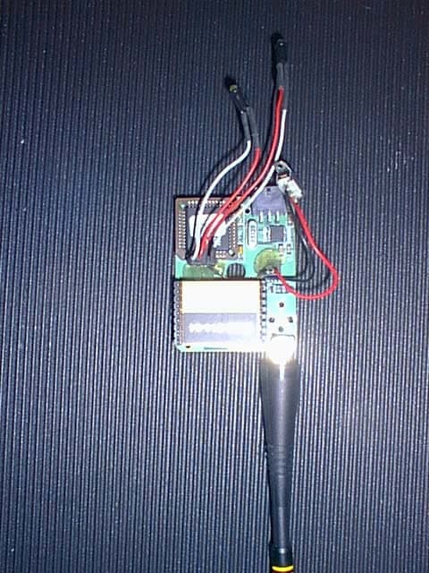
Click to zoom
Application Details
- Equipment Class
- DXT - Part 15 Low Power Transceiver, Rx Verified
- Date of Grant
- Jan 15, 2003
- Application Purpose
- Original Equipment
- Date of Application
- Jan 15, 2003
- Equipment Note
- Transceiver Module
- Frequency Range
- 914.50000000 - 914.50000000
- Company
- HQ, Inc.
- Country
- United States
Documents & Files
Document Text
Text extracted from the exhibit documents filed with the FCC. Open a document above to read the original.
Users Manual
CorTemp™ Wireless Temperature/Heart Rate Monitoring System Model No. HT150010/HT150009 Hardware Operational Instructions US Version 1.0 – December 2002 HQ, Inc. 210 9 th Street Drive West Palmetto, FL 34222 941-721-7588, ext. 11 • Fax 941-729-5480 Email: HTI2000@gte. Net Website: HQInc. us 2 TABLE OF CONTENTS I. System Overview Page 3 II. System Requirements Page 4 III. RF System Set-Up Page 4 III.1 CorTemp™ Page 4 III.2 RF Central Receiving Station Page 4 III.3 RF Remote Transmitter Page 5 III.4 Computer Page 5 III.5 Diagnostics System Test Page 7 III.6 CorTemp™/RF Remote Transmitter Unit Placement Page 7 IV. RF Remote Transmitter Page 8 IV.1 Product Features Page 8 IV.2 Specifications Page 8 V. RF Central Receiving Station Page 9 V.1 PC Requirements Page 9 V.2 Product Features Page 9 V.3 Specifications Page 9 VI. Warranty Page 10 VII. Customer Service/Repair Page 10 FCC Notice NOTE: This equipment has been tested and found to comply with the limits for a Class B digital device, pursuant to part 15 of the FCC rules. These limits are designed to provide reasonable protection against harmful interference in a residential installation. This equipment generates, uses and can radiate radio frequency energy and, if not installed and used in accordance with the instructions, may cause harmful interference with radio communications. However, there is no guarantee that interference will not occur in a particular installation. If this equipment does harmful interference to radio or television, which can be determined by turning the equipment off and on, the user is encouraged to try to correct the interference by one or more of the following measures. Reorient or relocate the receiving antenna. Increase the separation between the equipment and the receiver. Connect the equipment into an outlet on a circuit different from that to which the receiver is connected. Consult the dealer or an experienced radio/TV technician. Warning: FCC regulations state that any unauthorized changes or modifications to this equipment not expressly approved by HQ, Inc. could void the user’s authorization to operate this equipment. FCC ID# QQBHT130022 3 I. System Overview The CorTemp™ Wireless Monitoring System is designed to remotely monitor the core body temperature and heart rate of single or multiple subjects in real-time. The system hardware consists of an RF Central Receiving Base Station and one or more personal monitoring sets that include a CorTemp™ Ambulatory Data Recorder, RF Remote Transmitter and an optional Polar™ Heart Rate Chest Belt which are worn by the subject. The base station allows 1-20 subjects to move freely within a 200-300 ft. line of sight distance. Distances will vary depending on the environmental surrounding. The system is supported by central station software that displays the individual physiological data of each subject. (See Figure 1.) Figure 1. 4 II. System Requirements Table 1. represents the minimal hardware requirements to operate the wireless monitoring system. Additional CorTemp Data Recorders and RF Remote Transmitter sets (*) may be added to monitor up to 19 additional subjects. (Also, see Figure 2.) Component Product No. CorTemp™ 2002 Ambulatory Data Recorder (*) HT150001 RF Central Receiving Station HT500010 RF Remote Transmitter (*) HT500009 Polar Chest Belt (for HR Option only) (*) HT300005 PC Interface Cable HT300008 External Power Supply Connection HT250005 CorTrack™ RF 3.0 Operating Software Computer (Not Included With System) Table 1. III. RF System Set-Up Following are the steps to ensure proper set-up and functionality of the wireless RF system. Section III should be repeated for each personal monitoring set (*). III.1 CorTemp – (See Figure 2.) a. Insert a new battery into the CorTemp™ unit. Always use ONLY Duracell Coppertop, Energizer or Ultra Life Batteries for optimal performance. b. Program the CorTemp™ Data Recorder via the CorTrack™ Software, Version 3.8 or above or manually via the keypad. (Refer to Section III.2 in the CorTemp™ User’s Manual). NOTE: The serial port option must be “ON” for the system to function properly (Refer to Section III.2, 2.7 in the CorTemp™ User’s Manual.) and the collection interval must be set at a minimum of 20 seconds. (Refer to Section III.2, 2.3) c. Turn the unit “OFF”. d. Place the CorTemp Recorder in the carry pouch ensuring that the serial cable connection on the CorTemp™ Data Recorder is aligned with the cutout in the pouch for connection to the RF Remote Transmitter, leaving the pouch “open”. e. Connect the RF Remote Interface Cable through the pouch cutout to the CorTemp™ Data Recorder and then to the RF Remote transmitter. 5 f. Make written note of each RF Remote transmitter channel number (located on the back of the RF Remote unit) as to how it corresponds to its complimentary CorTemp™ Data Recorder. g. Repeat section III.1 for each additional CorTemp™ Data Recorder in the wireless system. III.2 RF Central Receiving Station – (See Figure 2.) a. Turn the unit “OFF”. b. External Power Supply – a. Plug the external DC power supply to the RF Central Receiving Station jack. b. Plug the AC connector into an AC power source. b. PC Interface Cable – a. Connect the 9 pin male DB9 connector to the female connector on the RF Central Receiving Station. III.3 RF Remote Transmitter – (See Figure 2.) Each RF Remote Transmitter has a unique channel ID number that is recognized by the RF Central Receiving Station. To ensure the integrity of the data collection, be sure to make note of the transmitter channel number as it corresponds to the CorTemp™ Data Recorder and subject you monitor. The RF Central Receiving Station will not recognize duplicate channel numbers. If you add personal monitoring sets to your system in the future, please ensure that you convey your existing channel numbers to HQ, Inc. customer service so you do not receive duplicate transmitter channel ID numbers. The transmitter channel ID number is etched on the back of th…
Text truncated - open the document above for the full version.
Cover Letter(s)
EMC Testing Laboratories, Inc. 2210 Justin Trail., Alpharetta, GA 30004 Curtis-Straus LLC December 31, 2002 527 Great Road Littleton, MA 01460 Attention: Mr. Barry Quinlan Subject: FCC Part 15 submittal for Certification of model HT130022. Gentlemen: On behalf of HQ, Inc., (FRN 0007691116) we at EMC Testing Laboratories, Inc., would like to submit a application to obtain a “Limited Modular Approval” for model HT130022 and would request that block diagrams, circuit schematics and the detailed theory of operation submitted for review for the module be withheld from public disclosure. This request is made under the provisions of Section 0.457 (d) and in accordance with 47 CFR 0.459. The information contained in the block diagrams, circuit schematics and the detailed theory of operation is proprietary information (trade secrets) and with the disclosed information competitive organizations would take considerable more time to assess and develop a workable competitive product. As a result, we believe that disclosure of these company guarded materials would compromise our leading position in this market. The model HT130022, is a data transmitter device, which is intended for use “only” in HQ, Inc. equipment. For your use in establishing this report and to obtain “Limited Modular Approval” we have addressed the 8 action item as indicated in the FCC Public Notice DA 00-1407, dated June 26,2000 as follows: 1. RF shielding – The purchased transmitter module from Radiometrix, part number BiM3-914- 64 is encased in a metal enclosure and therefore no additional shielding is considered necessary. 2. Excessive data rates – The model HT130022 is software controlled exclusively by HQ, Inc. software and as indicated in the duty cycle exhibit provided with the application has been maximized at a 60% duty cycle. 3. Power regulation – The module is provided with its own power supply regulation. Additionally, the applicant controls the type of input power by the use of a specific external power supply, (as indicated in the test report) or is powered by a 9Vdc battery. 4. Antenna requirements – The module is provided with either a reverse sma antenna connector or permanently attached antenna. Both types of antennas are ¼ wave whip style antennas. 5. Standalone configuration – During the testing of this equipment the unit was tested in a standalone configuration and with the maximum length cables intended to be used. 6. FCC Label – Since the equipment is to be use exclusively in HQ, Inc. products, the manufacturer intends utilize a pressure sensitive label, (which is intended to last the life of the product) on the outside of all equipment that the module is utilized. 7. Instructions for use – Since this product is for use only within HQ, Inc. equipment and since HQ, Inc. shall maintain full control of the product the following criteria shall be insured during manufacture and use of the product. A. The module will not be modified from its original certified configuration B. The module will be installed in a manner to eliminate possible coupling effects such as, routing all internal power and data wiring away from module. C. The module will be limited to a maximum 60% duty cycle as controlled by HQ, Inc., communication software. 8. A RF exposure requirement – The module operates under section 15.249 and has no RF exposure requirements. Additionally, we have enclosed a completed 731 form, application and confidentiality fees, in the amount of $1,235.00. Should you have any questions or comments, please do not hesitate to contact us. Kent Stewart Laboratory Manager EMC Testing Laboratories Phone: (770) 475-8819 Visit our home page at www.emctesting.com Fax: (770) 475-2011
Cover Letter(s)
From: "Kent Stewart" <[email protected]> To: "Curtis-Straus Certification Dept." <[email protected]> Sent: Tuesday, January 14, 2003 9:05 AM Attach: 02-186Areport.doc; manufacturers letter.doc Sub ject: Re: HQ FCC ID: QQBHT130022 "REPLY" Page 1 of 2 1/16/2003 Hi Barry, The following is in reply to you email. 1. The 10KHz bandwidth reference was a typographical error. For confirmation of this please view the pictures provided with the report, which show the RBW set to 100Khz. For your use I am including a revised report to show the appropriate RBW. 2. As discussed on the telephone HQ, Inc. will be in full charge of the modules design and intends to provide the regulated DC switching power with units that require connection to the AC mains. Additionally, a note to the user shall also be included the manual to use only the power supply provided with the equipment, (See the attached manufacturers letter). 3.I have re-evaluated the module for compliance to the new conducted emission limits. All signals in the 150KHz to 450KHz range, (i.e. range not previously evaluated) were a minimum of 25dBuV below the limit and therefore are not included in the revised report, (see attached revised report). Please use the "CE" note on the approval since this device has shown compliance with the conducted emissions limits in 15.107 adopted under FCC02-157 (ET Docket 98-80) and may be marketed after July 11, 2004 and is not affected by the 15.37(j) transition provisions. 4. Yes a 50 ohm/ 50uH LISN was used during conducted testing. 5. The manual is being revised to indicate to the user to use only the provided shielded cables provided with the product, (see the attached manufacturers letter). Please let me know if the manufacturers letter for items 2 and 4 are sufficient information. Thank you Kent Stewart EMC Testing Laboratories PH; 770-475-8819 ext. 13 ----- Original Message ----- From: Curtis -Straus Certification Dept. To: Kent Stewart Sent: Friday, January 10, 2003 5:53 PM Subject: HQ FCC ID: QQBHT130022 Hi Kent, Our reviewers have identified the following issues: 1. The write-up on page 15 of the test report states that a 10KHz minimum bandwidth was used for the fundamental emissions measurements. Is this a typographical error? 100KHz is the minimum RBW proscribed. If not an error, please provide new data measured with a 100KHz or greater RBW. 2. Please provide data responsive to the voltage variations requirements of 15.31(e). 3. We note that you have elected to use the old limits for line conducted emissions. This will result in a grant note revoking the grant on July 10, 2005. 4. Please confirm a 50 ohm/50 uH LISN was used during the conducted tests. 5. The manual does not state that a shielded RS232 serial shall be used. Best regards Barry C. Quinlan Certification Manager Curtis-Straus TCB Page 2 of 2 1/16/2003
Cover Letter(s)
January 13, 2003 Mr. Kent Stewart EMC Testing Laboratories, Inc. 2210 Justin Trail Alpharetta, GA 30004 Ref: HQ Inc. Product No. HT130002 Dear Kent: The external power source which is used to power the base station, is a regulated DC switching supply which can work on input AC power sources as defined in the external power source specification in our user’s manual. We will be using a DB 9 shielded cable for the serial cable connection between the computer and base station and we will use a special 6 pin shielded cable that we manufacture for the connection between the CorTemp and the RF remote unit as specified in our user’s manual. We will modify our user’s manual to include a statement to use only the provided components (shielded RS-232 cable & power supply) that are supplied with the system. Sincerely, HQ, Inc. William S. Hicks President /sys HQ, Inc. 210 9 th Street Drive West #208-210, Palmetto, FL 34221 941-721-7588 • FAX 941-729-5480• Email: [email protected] • Website: htitech.com
Cover Letter(s)
EMC Testing Laboratories, Inc. 2210 Justin Trail., Alpharetta, GA 30004 Curtis-Straus LLC December 31, 2002 527 Great Road Littleton, MA 01460 Attention: Mr. Barry Quinlan Subject: FCC Part 15 submittal for Certification of model HT130022. Gentlemen: On behalf of HQ, Inc., (FRN 0007691116) we at EMC Testing Laboratories, Inc., would like to submit a application to obtain a “Limited Modular Approval” for model HT130022 and would request that block diagrams, circuit schematics and the detailed theory of operation submitted for review for the module be withheld from public disclosure. This request is made under the provisions of Section 0.457 (d) and in accordance with 47 CFR 0.459. The information contained in the block diagrams, circuit schematics and the detailed theory of operation is proprietary information (trade secrets) and with the disclosed information competitive organizations would take considerable more time to assess and develop a workable competitive product. As a result, we believe that disclosure of these company guarded materials would compromise our leading position in this market. The model HT130022, is a data transmitter device, which is intended for use “only” in HQ, Inc. equipment. For your use in establishing this report and to obtain “Limited Modular Approval” we have addressed the 8 action item as indicated in the FCC Public Notice DA 00-1407, dated June 26,2000 as follows: 1. RF shielding – The purchased transmitter module from Radiometrix, part number BiM3-914- 64 is encased in a metal enclosure and therefore no additional shielding is considered necessary. 2. Excessive data rates – The model HT130022 is software controlled exclusively by HQ, Inc. software and as indicated in the duty cycle exhibit provided with the application has been maximized at a 60% duty cycle. 3. Power regulation – The module is provided with its own power supply regulation. Additionally, the applicant controls the type of input power by the use of a specific external power supply, (as indicated in the test report) or is powered by a 9Vdc battery. 4. Antenna requirements – The module is provided with either a reverse sma antenna connector or permanently attached antenna. Both types of antennas are ¼ wave whip style antennas. 5. Standalone configuration – During the testing of this equipment the unit was tested in a standalone configuration and with the maximum length cables intended to be used. 6. FCC Label – Since the equipment is to be use exclusively in HQ, Inc. products, the manufacturer intends utilize a pressure sensitive label, (which is intended to last the life of the product) on the outside of all equipment that the module is utilized. 7. Instructions for use – Since this product is for use only within HQ, Inc. equipment and since HQ, Inc. shall maintain full control of the product the following criteria shall be insured during manufacture and use of the product. A. The module will not be modified from its original certified configuration B. The module will be installed in a manner to eliminate possible coupling effects such as, routing all internal power and data wiring away from module. C. The module will be limited to a maximum 60% duty cycle as controlled by HQ, Inc., communication software. 8. A RF exposure requirement – The module operates under section 15.249 and has no RF exposure requirements. Additionally, we have enclosed a completed 731 form, application and confidentiality fees, in the amount of $1,235.00. Should you have any questions or comments, please do not hesitate to contact us. Kent Stewart Laboratory Manager EMC Testing Laboratories Phone: (770) 475-8819 Visit our home page at www.emctesting.com Fax: (770) 475-2011
Operational Description
1 DUTY CYCLE FORMULA I. TRANSMIT DATA BYTES BYTE VALUES PURPOSE/USE CODE ONES AAH PREAMBLE 10101010 4 1 DATA 00110001 3 2 DATA 00110010 3 3 DATA 00110011 4 4 DATA 00110100 3 5 DATA 00110101 4 6 DATA 00110110 4 7 DATA 00110111 5 8 DATA 00111000 3 9 DATA 00111001 4 0 DATA 00110000 2 0DH CR 00001101 3 0AH LF 00001010 2 54H TEMP(T) 01010100 3 52H HEART® 01010010 3 20H SPACE 00100000 1 3AH COLON (:) 00111010 2 2CH COMMA (,) 00101100 3 D DATA MESS 01000100 2 R SYNC 01010010 3 06H MESS OK 00000110 2 26H SEND DATA 00100110 3 14H CMD 00010100 2 Q SYNC 01010001 3 11H RETRANS 00010001 2 2DH MINUS 00101101 4 2EH PERIOD 00101110 4 II. TRANSMISSION SPEC A. 4800 BAUD B. 1 START BIT AND 1 STOP BIT C. BIT SENT PER CHAR: 10 D. TRANSMISSION FOR ONE BIT: 2.0833XE-4 SEC E. TRANSMISSION FOR ONE BYTE (10 X 2.0833E-4): 2.083E-3 F. NO. OF BYTES TRANSMITTED FOR 100 MSEC: 48 BYTES III. MESSAGE FORMAT A. PREAMBLE BYTE NUMBER TOTAL ONES (ON TIME) AAH 50 50 X 5- 250 FFH 1 1 9 00H 1 1 1 Q 1 1 4 R 1 1 4 _ _ TOTAL 54 268 DUTY CYCLE FOR PREAMBLE=(BITS ON/(TOTAL BYTES x 10))x100% = (268/540) x 100% = (49%) TIME TO SEND PREAMBLE APPROXIMATELY 100 MSEC THIS REMAINS CONSTANT B. DATA TRANSMISSION MESSAGE FORMAT 1 BYTE TO ADDRESS (BINARY) 1 BYTE FROM ADDRESS (BINARY) 2 1 FUNCTION CMD ASCII 1 TOTAL NO. OF BYTES (BINARY) X BYTES MESSAGE (ASCII) 1 BYTE CRC (BINARY) 1 BYTE CRC (BINARY) C. TYPICAL MESSAGE (WORST CASE) HEADER BYTE BYTES NO. OF ONES TO ADDR EEH 6 FM ADD EEH 6 TOTAL BYTE MESS 6 __ TOTAL HEADER BITS ON 3 18 MESSAGE TEXT(TEMP ONLY) T17:17,-377.77 Temp Format TEMP DATA T 3 TIME 1 4 7 5 : 2 1 4 7 5 , 3 TEMP - 4 3 4 7 5 7 5 . 4 7 5 7 5 __ TEMP MESS BITS ON 58 14 58 MESSAGE TEXT (HEART) H17:17,177.7 Heart Format R 3 1 4 7 5 : 2 1 4 7 4 , 3 1 4 7 5 7 5 . 4 7 5 __ TEMP MESS BITS ON 12 48 D. DUTY CYCLE FOR VARIOS MESSAGE FORMATS 1. SINGLE MESSAGE (TEMP) HEADER,TEMP,TEMP,CRC BYTES ONES ON(TOTAL ONES ON + BYTES) HEADER 3 18+3 21 3 TEMP MESS 14 58+14 62 TEMP MESS 14 58+14 62 CRC (FFFFH) 2 16+2 18 __ __ TOTAL ON 33 163 DUTY CYCLE = (BITS ON/(BYTES x 10)) x 100% = (163/330) x 100% = (49.3%) 2. SINGLE MESSAGE (TEMP,HEART) HEADER,TEMP,HEART,CRC BYTES ONES ON(TOTAL ONES ON + BYTES) HEADER 3 18+3 21 TEMP 14 58+14 62 HEART 12 48+12 60 CRC 2 16+2 18 __ __ 31 161 DUTY CYCLE = (161/310) X 100% = 52% 3. MULTIPLE TEMP MESSAGE HEADER,6 SINGLE TEMP,CRC BYTES ONES ON HEADER 3 21 TEMP(12) 84 372 CRC 2 18 __ __ 89 411 DUTY CYCLE = (411/890)x100% = 46% 4. MULTIPLE TEMP,HEART MESSAGE HEADER,3 TEMP,3HEART,CRC BYTES ONES ON HEADER 3 21 TEMP(3) 42 182 HEART(3) 36 180 CRC 2 18 __ ___ 82 401 DUTY CYCLE = 401/820 x 100% = 48.9% E. SUMMARY MESSAGE PORTION DUTY CYCLE(DC) TOTAL BYTES 100 MSEC CYCLES(100MC) 1. PREAMBE 49.0 54 1.124 2. SINGLE TEMP MESS(STM) 49.3 33 0.689 3. SINGLE TEMP, HEART(STHM) 52.0 31 0.645 4. MULT TEMP MESS(MTM) 46.0 89 1.85 5. MULT TEMP,HR MESS(MTHM) 48.9 82 1.70 APPROXIMATELY 48 BYTES ARE SENT IN 100 MSEC CYCLE FOR TYPICAL MESSAGE 4 OVERALL WEIGHTED DUTY CYCLE PER 100MS(OWDCP100MS) =((100MC PREABLE)x(DC PREAMBLE)+(100MC STM)x(DC STM))/(100MSEC PREAMBLE+100MSEC STM) OWDCP100MS-STM = (1.124(49) + .69(49.3))/(1.124+.69) = 55+34/ 1.814 = 49% OWDCP100MS-STHM = (1.123(49)+ 0.645(52))/(1.12+0.645) = 55+33.5/1.765 = 50% OWDC100MS-MTM = (1.123(49)+1.85(46))/(1.12+1.85) = 55+85.1/2.97 = 47% 0WDC100MS-MTHM = (1.123(49)+1.7(48.9)/(1.12+1.7) = 55+83.1/2.82 = 48.9% UPON REVIEW OF TAKING THE TOTAL TRANSMISSION FOR A SINGLE TRANSMISSION AS WELL AS MULTIPLE READINGS TRANSMISSION, THE WEIGHTED AVERAGE DUTY CYCLES REMAINED UNDERS 51%. THEREFORE, WE WIIL ASSUME A DUTY CYCLE OF 60% FOR A WORST CASE TRANSMISSION DUTY CYCLE. 5
Test Report
RF Emissions Test Report To Determine Compliance With: FCC, Part 15 Rules and Regulations Model numbers: HT130022 Rev. B. December 17, 2002 Manufacturer: HQ, Inc. 210 9th Steet Drive Palmetto, FL 34221 EMC Testing Laboratories, Inc. authorizes the above company to reproduce this report provided it is reproduced in its entirety EMC Testing Lab. (770) 781-9228 Test report no. 02-186A Page 2 of 2 2 2 2 Contents Section General Information ....................................................................... 1 Test Summary.................................................................................. 2 Standard Reference ........................................................................ 3 Test Method .......................................................................... 4 Radiated Out of Band Emissions Measurements ........................... 5 Fundamental Frequency Radiated Emissions Measurements ......... 6 Radiated emission measurements in accordance with 15.109 ......... 7 EMC Testing Lab. (770) 781-9228 Test report no. 02-186A Page 3 of 2 2 2 2 Section 1 General Information Manufacturer: HQ, Inc. 210 9th Steet Drive Palmetto, FL 34221 Manufacturer representative: Mr. Bill Hicks Equipment covered by this report: Model no. HT130022 RF Rev. B. Options covered by this report: None Equipment serial no. Prototype Test specifications: To determine compliance with: FCC, Part 15, Subpart C Rules and Regulations, Class B Test report number: 02-186A Test commenced: November 1, 2002 Test completed: November 25, 2002 Test engineer: Kent Stewart Test Facility: The test facility used to perform these tests is on file with the FCC under registration number 637500 and located at: EMC Testing Laboratories, Inc. 2210 Justin Trail Alpharetta, GA 30004 EMC Testing Lab. (770) 781-9228 Test report no. 02-186A Page 4 of 2 2 2 2 Section 2 Test report summary sheet 1 of 3 Summary: Tests Results FCC, Part 15, Class B, Radiated emissions: Pass FCC, Part 15, Class B, Conducted emissions: Pass 1- The product(s) covered by this report was found to comply with the limits indicated in paragraph 15.109 Subpart B and 15.249, Part 15, Subpart C of the FCC Rules and Regulations. Product description: The product(s) covered by this report consisted of a RF Transceiver Module model HT130022 Rev. B., for use in HQ, Inc. equipment. The product is intended for use in transmitting body temperatures and heart rates received from a monitoring recorder via RS-232 cable. The EUT set to transmit at 914.5 MHz and utilizes a maximum 60% duty cycle. The unit can be powered from an external DC power source, (battery) or from an external power supply. The unit was tested with and may be provided with one of two different ¼ wavelength antenna’s. Antenna part number S331C, is a BNC style antenna that has been permanently mounted with the use of a metal epoxy which permanently bonds the male and female connector shells together. The antenna part number ANT-916-CW-QW, utilizes a unique reverse SMA type connector. To determine a worst case configuration preliminary scans were performed on two configurations, 1) with the EUT powered by a 9V battery and 2) with the EUT powered by an external switching power supply. Final testing was performed with the EUT being powered by the external switching power supply and was also tested with both antenna types. EMC Testing Lab. (770) 781-9228 Test report no. 02-186A Page 5 of 2 2 2 2 Test report summary sheet 2 of 3 Test configuration: The equipment under test was set-up and configured as specified by the manufacturer. 1- The EUT was connected to the following support peripherals to simulate a monitoring device and to make the EUT to continually transmit. During the test the receiver was disabled. A) A laptop computer, manufactured by IBM, model no. 2611-410, serial no. AA- D2PFF 98/12, FCC marked. B) A power supply, manufactured by CUI Stack, part number DTS120250U2/AC1- P5, serial number M04203917A1. 2- During the testing of the EUT utilized the following cables and were connected as indicated below. A) A Shielded RS-232 cable provided with a power input adapter plug was connected from the EUT’s communication/power port to the computer’s RS-232 port. The power adapter plug was connected to an unshielded power cable integral to the power supply. Test operation: For all measurements, the equipment under test was and caused to function in a continuous mode of operation for maximum electrical activity as specified by the manufacturer. Specifically, the EUT was made to continually transmit data being provided from the computers software program. Modifications: The following modifications were required to comply with the indicated limits: 1- None EMC Testing Lab. (770) 781-9228 Test report no. 02-186A Page 6 of 2 2 2 2 Test report summary sheet 3 of 3 Conclusion: With the above indicated modifications, the product(s) covered by this report has been tested and found to comply with the limits indicated in paragraph 15.249 of the FCC, Part 15, Subpart C Rules and Regulations and all subsequent limits indicated therein for a class B device. Tested by: Reviewed by: Kent Stewart Gene J. Bailey Laboratory Manager Engineering Manager EMC Testing Laboratories, Inc. EMC Testing Laboratories, Inc. December 17, 2002 December 17, 2002 EMC Testing Lab. (770) 781-9228 Test report no. 02-186A Page 7 of 2 2 2 2 Section 2 cont... This page intentionally left blank. (Reserved for future use) EMC Testing Lab. (770) 781-9228 Test report no. 02-186A Page 8 of 2 2 2 2 Section 3 STANDARD REFERENCE The following primary standards were used for this test: 1) ANSI C63.4-1992: Method of Measurements of Radio-Noise Emissions from Low- Voltage Electrical and Electronic Equipment in the 9 Khz to 40 Ghz. 2) US Code of Federal Regulations (CFR) 1998: Title 47, Part 15, Radio Frequency Devices, Subpart C, Intentional Radiators. EMC Testing Lab. (770) 781-9228 Test report no. 02-186A Page 9 of 2 2 2 2 Section 4 TEST METHOD INTROD…
Text truncated - open the document above for the full version.
Contact Information
Applicant
William S Hicks(President)
Test Firm
EMC Testing Laboratories, Inc.Gene Bailey
Technical Specifications
| # | Rule Parts | Frequency Range | Power Output |
|---|---|---|---|
| 1 | 15C | 914.5 MHz - 914.5 MHz | - |