QR5ROTR00471ROTRONICS 915MHz RADIO MODULE
Rotronics Systems Limited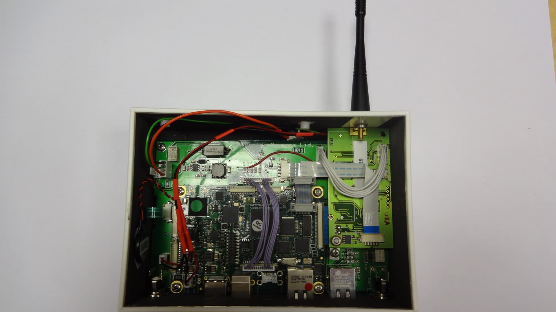
Click to zoom
Application Details
- Equipment Class
- DXT - Part 15 Low Power Transceiver, Rx Verified
- Date of Grant
- Jan 22, 2013
- Application Purpose
- Original Equipment
- Date of Application
- Jan 22, 2013
- Equipment Note
- ROTRONICS 915MHz RADIO MODULE
- Frequency Range
- 915.00000000 - 915.00000000
- Company
- Rotronics Systems Limited
- Country
- United Kingdom
Documents & Files
Document Text
Text extracted from the exhibit documents filed with the FCC. Open a document above to read the original.
Users Manual
Rotronics Systems Limited MiWi module – FRZ200 – 1000 Module user guide – Rotronics Systems internal use only. 1.1General description This module is a radio data transmitter / receiver using FSK modulation operating on 915mHz for short range telemetry. It has been developed for Next Control Systems in the UK as a component module part of a remote temperature measurement system. 1.2Warning notice The module RF stage is not to be modified in any way without repeating RF compliance testing. The RF and micro-controller stages must not be fed from a DC supply greater than 3.6v. No other antenna apart from the 1/4wave screw on antenna may be used with this module. 1.3Technical specifications Operating frequency 915.000mHz. RF power output 90.9dBuV/m (-15dB). Modulation FSK 200kHz deviation. DC power supply 3.6v DC. Inputs analogue (0-2.500v) and digital (I2C). 1.4Hardware description The module circuit board measures 80mm long x 42mm wide. Height with battery fitted is 20mm. Primary electrical interconnections are via a 9 way FFC connector. There are links for setting options, see 1 . 5 below, and connections for in-circuit programming of the processor and reading the unique MAC address back for identifying individual modules. 1.5Circuit description Read in conjunction with “Transmitter120.pdf” circuit diagram. The RF chip (IC1) is an integrated, single chip ISM band sub-GHz transceiver. It has a inbuilt frequency synthesiser clocked by a external 10mHz crystal and generates 915mHz radio frequency. The receiver is zero-IF architecture and has the following components: LNA, down conversion mixer, channel filter, baseband limiting amplifier and received signal strength indication (RSSI). IC 1 has an internal transmit / receive switch with a external impedance matching network coupling to the screw-on 1/4wave antenna. The quality of received data is checked and validated with RSSI and DQI (Data Quality Indicator) blocks built in internally. The RF transceiver chip is controlled through a 4-wire SPI bus from a Microchip controller on the module. The SPI bus is connected to two local memory chips, the MAC address chip (IC3) which is pre-loaded with a unique address for each module, and a EEPROM memory (IC2) to store data blocks if the transceiver is unable to communicate with it's host for a period. The Microchip controller (IC4) has two clocks, a standard clock crystal (32.768kHz) for the period timing and an internal 12mHz oscillator for the processor clock. The controller has three 10bit ADC ports, a USB port and a I2C serial data port. A board mounted 3v6 Li-SOCI cell is the normal source of power when the module is used with an analogue signal conditioning option board to measure temperature with a probe. External 5v DC power connection when the unit is used in the controller is regulated on the module to 3v3 DC. The module has three possible modes of operation, as a remote radio data transceiver, a repeater to pass the data through, and a controller which communicates with the remote data transceivers. These options are set using solder bridges on Lk1 and Lk2 Remote radio data transceiver – no links Repeater radio transceiver – link Lk2 Controller for network – link Lk1 & Lk2 1.5Board interconnections Read in conjunction with “Transmitter120.pdf” circuit diagram Cn 1 – M4 threaded fixer for ¼ wave antenna. Cn 2 – Programming header for manufacturing use only. Cn 3 – Data and power connector for MAC reading and control. Cn 4 - Panel reset switch – membrane connector. Cn 5 – Analogue and I2C connections to signal conditioning option boards. Cn 6 – Connector for temperature and humidity module (Sensiron part). 1.6System description The controller, model number GENII/WARP/200, monitors and stores readings from the remote transmitters, displaying parameters on a 4.3” LCD display, with toggle buttons on a panel membrane to view readings from the different remote transmitters. The controller comprises a MiWi module ( FRZ200 – 1000 ), an embedded computer module (Re2) and a mother board that holds these two units, provides DC voltage power conversion, and interfaces to the LCD screen mounted on it's rear. The controller is powered by a plug top DC power supply, 15v 5w. - The remote transmitter, model number GENII/FRZ/200A and B, measures up to two temperatures using platinum temperature probes. The remote transmitter comprises a MiWi module ( FRZ200 – 1000 ) and an analogue signal conditioning option module that can be set to different ranges, A and B. The remote transmitter is powered by a 3v6 LiSOCI cell. Energy saving techniques are used to achieve up to 4 year battery life. - The repeater, model number GENII/SRPT/200, receives remote transmitter's in it's vicinity and automatically associates itself with either a controller, or another repeater to pas the data back to the controller. The repeater comprises a MiWi Module (FRZ200 – 1000 ) and a battery backup board to provide a 21 hour backup in the event of mains loss. The controller is powered by a plug top DC power supply, 12v 1w. - 1.7Module operation A remote radio data transceiver, when first powered up or, whenever the front membrane button is pressed and released, will transmit association data packets based on the unique MAC address factory set in IC3. The controller will receive these data packets, and pass them to an embedded computer module which checks that the MAC address of the transmitter module exists within its database. If the MAC address is not in the embedded computer module table then it will not respond to the remote transmitter. If the MAC address is in the computer table then it will transmit an acknowledgement to the remote transmitter and an association communications link is created between the specific remote transmitter and the controller. Up to 120 remote transmitters can be used. Thereafter, at 60 second intervals, the remote transmitter will wake up, transmit its sensor values to the controller, and wait for an ackn…
Text truncated - open the document above for the full version.
Cover Letter(s)
Rotronics Systems Limited Unit 5 Riverside Park Farnham Surrey GU9 7UG 01252 72268 30 th November 2012 Limited Modular Approval Request Timco Engineering Inc. 849 NW State Road 45 Newberry FI 32669 RE:FCC Limited Modular Approval FCC ID: QR5ROTR00471 To whom it may concern: Pleased be advised that the manufacturer requests that the above referenced model be approved for Limited Modular Approval in accordance with FCC Rules and Regulations. Thank you for your attention to this matter. Yours faithfully Rotronics Systems Limited Robert E Head Managing Director
Cover Letter(s)
Rotronics Systems Limited Unit 5 Riverside Park Farnham Surrey GU9 7UG 01252 72268 30 th November 2012 Letter of Agency Timco Engineering Inc. 849 NW State Road 45 Newberry FI 32669 To whom it may concern; We certify that we are not subject to denial of federal benefits, that includes FCC benefits, persuant to Section 5301 of the Anti-Drug Abuse ACT of 1988, U.S.C. 862. Further, no party, as defined in 47 CFR 1.2002(b), to the application, is subject to denial of federal benefits, that includes FCC benefits. Thank you for your attention to these matters. Yours faithfully Rotronics Systems Limited Robert E Head Managing Director
Cover Letter(s)
Rotronics Systems Limited Unit 5 Riverside Park Farnham Surrey GU9 7UG UK 00 44 1252 722686 21 st January 2013 Federal Communications Commission Authorization and Evaluation Division Reference FRZ200-1000 MiWi transceiver - FCC ID: QR5ROTR00471. We are seeking 'Limited Modular Approval' for the FRZ200-1000MiWi transceiver. The requirements for 'Modular Approval' are; 1)The radio elements must have the radio frequency circuitry shielded. - not compliant 2)The module has buffered modulation/ data inputs ensuring that the device complies with Part 15 requirements with any type of input signal. 3)The module includes power supply regulation as a part of it's design. 4)The module has a unique antenna connector and is to be marketed with a specific antenna only. 5)The module has demonstrated compliance in a stand alone configuration. 6)The module is labelled with a permanent FCC label. 7)The module complies with all specific rules applicable to the transmitter including the conditions which are a part of the integration instructions when assembled. 8)The module complies with RF exposure requirements. The FRZ200-1000 complies with all the above except for 1) the screening over the RF circuitry. We are seeking 'Limited Modular Approval' on the basis that it will only be used in the following three final products: Controller, model number GENII/WARP/200 Remote Transmitter, model number GENII/FRZ/200A & B Repeater, model number GENII/SRPT/200 The test report shows results for both a) Standalone configuration. and b) Incorporation in the three host products. Sincerely, Robert E Head Rotronics Systems Limited
Cover Letter(s)
Rotronics Systems Limited Unit 5 Riverside Park Farnham Surrey GU9 7UG UK 00 44 1252 722686 23 rd January 2013 Federal Communications Commission Authorization and Evaluation Division Confidentiality Request regarding application for certification of FCC ID: QR5ROTR00471 Pursuant to Sections 0.457 and 0.459 of the Commission’s Rules, we hereby request confidential treatment of information accompanying this application as outlined below: Exhibit Type Circuit Diagram Circuit Description Bill of Materials File Name FRZ200-1000Schem.pdf FRZ200-1000OpDes.pdf FRZ200-1000PartsLst.pdf The above materials contain trade secrets and proprietary information not customarily released to the public. The public disclosure of these materials may be harmful to the applicant and provide unjustified benefits to its competitors. The applicant understands that pursuant to Section 0.457 of the Rules, disclosure of this application and all accompanying documentation will not be made before the date of the Grant for this application. Sincerely, Robert E Head Rotronics Systems Limited
External Photos
Remote Transmitter GENII/FRZ/200 A & B External view Internal view Temperature sensor board removed – switch selectable options A & B Repeater GENII/SRPT/200 External view c/w Power Module Internal view with Battery Module Controller WARP GENII/WARP/200 External view c/w Power Module Internal view
ID Label/Location Info
Next Control Systems Ltd Data Transceiver GENII/FRZ/200/A Contains FCC ID : QR5ROTR00471 This device complies with section 15 of the FCC rules. Operation is subject to the following 2 conditions: This device may not cause harmful interference and 2. This device must accept any interference received including interference that may cause undesired operation.
ID Label/Location Info
Next Control Systems Ltd WARP GENII/WARP/200 Contains FCC ID : QR5ROTR00471 This device complies with section 15 of the FCC rules. Operation is subject to the following 2 conditions: This device may not cause harmful interference and 2. This device must accept any interference received including interference that may cause undesired operation.
ID Label/Location Info
Next Control Systems Ltd Repeater GENII/SRPT/200 Contains FCC ID : QR5ROTR00471 This device complies with section 15 of the FCC rules. Operation is subject to the following 2 conditions: This device may not cause harmful interference and 2. This device must accept any interference received including interference that may cause undesired operation.
Test Report
|---------- ( Cambridge Ltd. ) ----------| Testing EMCEMC Consultancy EMC Training or : 01223 241140 (accounts) 23, Headington Drive, Cambridge. CB1 9HE Tel : 01954 251974 (test site) Fax : 01954 251907 email: [email protected] web : www.dbtechnology.co.uk REPORT ON ELECTROMAGNETIC COMPATIBILITY TESTS Performed at: TWENTY PENCE TEST SITE Twenty Pence Road, Cottenham, Cambridge U.K. CB24 8PS on Rotronics Systems Limited MiWi Module - FRZ200-1000 dated 24th October 2012 Document History DBDSAdded appendix A03/01/132 Initial release09/11/121 Approved by Revised by Description of modifications Affected page(s) DateIssue Based on report template: v090319 1 of 77 Page: Test Report T4521 Test No: FCC ID: QR5ROTR00471 R3167 2 Report No: Issue No: This report shall not be reproduced except in full, without the written approval of: dB Technology (Cambridge) Ltd. Equipment Under Test (EUT):MiWi Module - FRZ200-1000 Test Commissioned by:Rotronics Systems Limited Unit 5 Riverside Park Farnham Surrey GU9 7UG Representative:Bob Head Test Started:16th October 2012 Test Completed:22nd October 2012 Test Engineer:Dave Smith Date of Report:24th October 2012 Written by:Dave SmithChecked by:Derek Barlow Signature:Signature: Date:24th October 2012Date:9th November 2012 dB Technology can only report on the specific unit(s) tested at its site. The responsibility for extrapolating this data to a product line lies solely with the manufacturer. Test Standards Applied CFR 47Code of Federal Regulations: Pt 15 Subpart C - Radio Frequency Devices - Intentional Radiators RSS-210Licence-exempt Radio Apparatus (All Frequency Bands): Issue 8Category I Equipment In particular, the rules of FCC part 15.249 and the rules of RSS-210 A2.9 were applied. 2 of 77 Page: Test Report T4521 Test No: FCC ID: QR5ROTR00471 R3167 2 Report No: Issue No: This report shall not be reproduced except in full, without the written approval of: dB Technology (Cambridge) Ltd. Emissions Test Results Summary CFR 47PASS TestPortMethodLimitPASS/FAILNotes Conductedac powerANSI C63.4:2003 15.207PASS Emissions Radiated ANSI C63.4:2003 15.249PASS Emissions & 15.209 specs_fccv100412 RSS-210PASS TestPortMethodLimitPASS/FAILNotes Radiated ANSI C63.4:2003 RSS-210 A2.9PASS Emissions 3 of 77 Page: Test Report T4521 Test No: FCC ID: QR5ROTR00471 R3167 2 Report No: Issue No: This report shall not be reproduced except in full, without the written approval of: dB Technology (Cambridge) Ltd. Contents 44 8.4 Radiated Emissions Results - Data Transceiver - Carrier and Band Edges . . . . . . . . . . . . . . . . . .. . . 43 8.3 Radiated Emissions Results - Below 30MHz . . . . . . . . . . . . . . . . . . . . . . . . . . . . . . . . . . . . . . . . . . . . . . . 42 8.2 Conducted Emissions (Power) - Results - Repeater . . . . . . . . . . . . . . . . . . . . . . . . . . . . . . . . . . . . . . . . 41 8.1 Conducted Emissions (Power) - Results - Controller . . . . . . . . . . . . . . . . . . . . . . . . . . . . . . . . . . . . . . . . 40 8 Appendix A: Test Results . . . . . . . . . . . . . . . . . . . . . . . . . . . . . . . . . . . . . . . . . . . . . . . . . . .. . . . . . . . . . . . 40 Photograph 19 Radiated Emissions - Below 30MHz - Controller . . . . . . . . . . . . . . . . . . . . . . . . . . . . . . . . . 39 Photograph 18 Radiated Emissions - Below 30MHz - Repeater . . . . . . . . . . . . . . . . . . . . . . . . . . . . . . . . . . . 39 Photograph 17 Radiated Emissions - Below 30MHz - Data Transceiver . . . . . . . . . . . . . . . . . . . . . . . . . . . . 38 Photograph 16 Radiated Emissions - Data Transceiver - Flat . . . . . . . . . . . . . . . . . . . . . . . . . . . . . . . . . . . . 38 Photograph 15 Radiated Emissions - Data Transceiver - Upright . . . . . . . . . . . . . . . . . . . . . . . . . . . . . . . . . 37 Photograph 14 Radiated Emissions - Repeater - Flat . . . . . . . . . . . . . . . . . . . . . . . . . . . . . . . . . . . . . . . . . . . 37 Photograph 13 Radiated Emissions - Repeater - Upright . . . . . . . . . . . . . . . . . . . . . . . . . . . . . . . . . . . . . . . . 36 Photograph 12 Radiated Emissions - Controller - Flat . . . . . . . . . . . . . . . . . . . . . . . . . . . . . . . . . . . . . . . . . . 36 Photograph 11 Radiated Emissions - Controller - Upright . . . . . . . . . . . . . . . . . . . . . . . . . . . . . . . . . . . . . . 35 Photograph 10 Conducted Emissions - Repeater - Back . . . . . . . . . . . . . . . . . . . . . . . . . . . . . . . . . . . . . . . . . 35 Photograph 9 Conducted Emissions - Repeater - Front . . . . . . . . . . . . . . . . . . . . . . . . . . . . . . . . . . . . . . . . . 34 Photograph 8 Conducted Emissions - Controller - Back . . . . . . . . . . . . . . . . . . . . . . . . . . . . . . . . . . . . . . . . 34 Photograph 7 Conducted Emissions - Controller - Front . . . . . . . . . . . . . . . . . . . . . . . . . . . . . . . . . . . . . . . . 33 7.1 Radiated Emissions below 30MHz . . . . . . . . . . . . . . . . . . . . . . . . . . . . . . . . . . . . . . . . . . . . . . . . . . .. . . . 33 7 Test Methods . . . . . . . . . . . . . . . . . . . . . . . . . . . . . . . . . . . . . . . . . . . . . . . . . . .. . . . . . . . . . . . . . . . . . . . . . . . 32 6 Test Equipment (used for measurements recorded in Appendix A) . . . . . . . . . . . . . . . . . . . . . . . . 31 Figure 2 General Arrangement of EUT and Peripherals . . . . . . . . . . . . . . . . . . . . . . . . . . . . . . . . . . . . . . . . 30 5.1 General . . . . . . . . . . . . . . . . . . . . . . . . . . . . . . . . . . . . . . . . . . . . . . . . . . .. . . . . . . . . . . . . . . . . . . . . . . . . . . . 30 5 Appendix A Details . . . . . . . . . . . . . . . . . . . . . . . . . . . . . . . . . . . . . . . . . . . . . . . . . . .. . . . . . . . . . . . . . . . . . 28 PLOT 11 99% Occupied Bandwidth . . . . . . . . . . . . . . . . . . . . . . . . . . . . . . . . . . . . . . . . . . . . . . . . . . .. . . . 27 PLOT 10 Radiated Emissions - Pulse Width . . . …
Text truncated - open the document above for the full version.
Test Setup Photos
|---------- ( Cambridge Ltd. ) ----------| Testing EMCEMC Consultancy EMC Training or : 01223 241140 (accounts) 23, Headington Drive, Cambridge. CB1 9HE Tel : 01954 251974 (test site) Fax : 01954 251907 email: [email protected] web : www.dbtechnology.co.uk REPORT ON ELECTROMAGNETIC COMPATIBILITY TESTS Performed at: TWENTY PENCE TEST SITE Twenty Pence Road, Cottenham, Cambridge U.K. CB24 8PS on Rotronics Systems Limited MiWi Module - FRZ200-1000 dated 24th October 2012 Document History DBDS2 and 6 onwards08/01/122 Initial release24/10/121 Approved by Revised by Description of modifications Affected page(s) DateIssue Based on report template: v090319 1 of 13 Page: Test Photos T4521 Test No: FCC ID: QR5ROTR00471 R3167 2 Report No: Issue No: This report shall not be reproduced except in full, without the written approval of: dB Technology (Cambridge) Ltd. Contents 13 Photograph 19 Radiated Emissions - Below 30MHz - Controller . . . . . . . . . . . . . . . . . . . . . . . . . . . . . . . . . 12 Photograph 18 Radiated Emissions - Below 30MHz - Repeater . . . . . . . . . . . . . . . . . . . . . . . . . . . . . . . . . . . 12 Photograph 17 Radiated Emissions - Below 30MHz - Data Transceiver . . . . . . . . . . . . . . . . . . . . . . . . . . . . 11 Photograph 16 Radiated Emissions - Data Transceiver - Flat . . . . . . . . . . . . . . . . . . . . . . . . . . . . . . . . . . . . 11 Photograph 15 Radiated Emissions - Data Transceiver - Upright . . . . . . . . . . . . . . . . . . . . . . . . . . . . . . . . . 10 Photograph 14 Radiated Emissions - Repeater - Flat . . . . . . . . . . . . . . . . . . . . . . . . . . . . . . . . . . . . . . . . . . . 10 Photograph 13 Radiated Emissions - Repeater - Upright . . . . . . . . . . . . . . . . . . . . . . . . . . . . . . . . . . . . . . . . 9 Photograph 12 Radiated Emissions - Controller - Flat . . . . . . . . . . . . . . . . . . . . . . . . . . . . . . . . . . . . . . . . . . . 9 Photograph 11 Radiated Emissions - Controller - Upright . . . . . . . . . . . . . . . . . . . . . . . . . . . . . . . . . . . . . . . 8 Photograph 10 Conducted Emissions - Repeater - Back . . . . . . . . . . . . . . . . . . . . . . . . . . . . . . . . . . . . . . . . . . 8 Photograph 9 Conducted Emissions - Repeater - Front . . . . . . . . . . . . . . . . . . . . . . . . . . . . . . . . . . . . . . . . . . 7 Photograph 8 Conducted Emissions - Controller - Back . . . . . . . . . . . . . . . . . . . . . . . . . . . . . . . . . . . . . . . . . 7 Photograph 7 Conducted Emissions - Controller - Front . . . . . . . . . . . . . . . . . . . . . . . . . . . . . . . . . . . . . . . . . 6 Photograph 6 Radiated Emissions - Flat . . . . . . . . . . . . . . . . . . . . . . . . . . . . . . . . . . . . . . . . . . . . . . . . . . .. . . 6 Photograph 5 Radiated Emissions - Upright, Close-up . . . . . . . . . . . . . . . . . . . . . . . . . . . . . . . . . . . . . . . . . . 5 Photograph 4 Radiated Emissions - Upright, Back . . . . . . . . . . . . . . . . . . . . . . . . . . . . . . . . . . . . . . . . . . . . . . 4 Photograph 3 Radiated Emissions - Upright, Front . . . . . . . . . . . . . . . . . . . . . . . . . . . . . . . . . . . . . . . . . . . . . 4 Photograph 2 Conducted Emissions - Back . . . . . . . . . . . . . . . . . . . . . . . . . . . . . . . . . . . . . . . . . . . . . . . . . . .. 3 Photograph 1 Conducted Emissions - Front . . . . . . . . . . . . . . . . . . . . . . . . . . . . . . . . . . . . . . . . . . . . . . . . . . . 2 of 13 Page: Test Photos T4521 Test No: FCC ID: QR5ROTR00471 R3167 2 Report No: Issue No: This report shall not be reproduced except in full, without the written approval of: dB Technology (Cambridge) Ltd. Photograph 1 Conducted Emissions - Front 3 of 13 Page: Test Photos T4521 Test No: FCC ID: QR5ROTR00471 R3167 2 Report No: Issue No: This report shall not be reproduced except in full, without the written approval of: dB Technology (Cambridge) Ltd. Photograph 2 Conducted Emissions - Back Photograph 3 Radiated Emissions - Upright, Front 4 of 13 Page: Test Photos T4521 Test No: FCC ID: QR5ROTR00471 R3167 2 Report No: Issue No: This report shall not be reproduced except in full, without the written approval of: dB Technology (Cambridge) Ltd. Photograph 4 Radiated Emissions - Upright, Back 5 of 13 Page: Test Photos T4521 Test No: FCC ID: QR5ROTR00471 R3167 2 Report No: Issue No: This report shall not be reproduced except in full, without the written approval of: dB Technology (Cambridge) Ltd. Photograph 5 Radiated Emissions - Upright, Close-up Photograph 6 Radiated Emissions - Flat 6 of 13 Page: Test Photos T4521 Test No: FCC ID: QR5ROTR00471 R3167 2 Report No: Issue No: This report shall not be reproduced except in full, without the written approval of: dB Technology (Cambridge) Ltd. Photograph 7 Conducted Emissions - Controller - Front Photograph 8 Conducted Emissions - Controller - Back 7 of 13 Page: Test Photos T4521 Test No: FCC ID: QR5ROTR00471 R3167 2 Report No: Issue No: This report shall not be reproduced except in full, without the written approval of: dB Technology (Cambridge) Ltd. Photograph 9 Conducted Emissions - Repeater - Front Photograph 10 Conducted Emissions - Repeater - Back 8 of 13 Page: Test Photos T4521 Test No: FCC ID: QR5ROTR00471 R3167 2 Report No: Issue No: This report shall not be reproduced except in full, without the written approval of: dB Technology (Cambridge) Ltd. Photograph 11 Radiated Emissions - Controller - Upright Photograph 12 Radiated Emissions - Controller - Flat 9 of 13 Page: Test Photos T4521 Test No: FCC ID: QR5ROTR00471 R3167 2 Report No: Issue No: This report shall not be reproduced except in full, without the written approval of: dB Technology (Cambridge) Ltd. Photograph 13 Radiated Emissions - Repeater - Upright Photograph 14 Radiated Emissions - Repeater - Flat 10 of 13 Page: Test Photos T4521 Test No: FCC ID: QR5ROTR00471 R3167 2 Report No: Issue No: This report shall not be reproduced except in full, without the w…
Text truncated - open the document above for the full version.
Contact Information
Applicant
Robert Edwin Head(Mr)
Test Firm
DB TechnologyDave Smith
Technical Specifications
| # | Rule Parts | Frequency Range | Power Output |
|---|---|---|---|
| 1 | 15C | 915 MHz - 915 MHz | - |